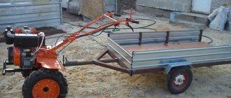
Assembly of a pendulum machine
The design of the pendulum machine consists of three main components:
- The bed is the simplest element of the machine for an angle grinder. The unit is made of a steel plate with a thickness of at least 10 mm with supports at the bottom. You can weld a frame from a profile pipe and sew 3 mm thick sheet metal on top. A bracket with a pendulum mechanism hinge is fixed to the frame.
- The pendulum is the main working mechanism of the machine. The structure in the shape of the letter “T” is welded from a profile pipe. A clamp for an angle grinder is fixed to one end, and the other side of the pendulum is attached to the hinge mechanism.
- The clamp for the grinder is made of metal brackets. The structure is firmly fixed to the pendulum through the console.
To make a machine, you will need a drawing or at least a simple diagram. One of the options is shown in the photo. The dimensions of the machine will have to be calculated according to the dimensions of the available grinder.
To correctly calculate the size of the machine components, first measure the dimensions of the angle grinder, and then the distance between the holes on the gear housing
When designing a pendulum, it is important to reduce the distance between the cutting disc of the grinder and the hinge mechanism to a minimum. This will give rigidity to the machine, which will allow for a more even cut.
After developing the drawing, we begin manufacturing all machine components:
- According to the dimensions of the diagram, metal blanks for all components are cut. First, the frame is made. It is necessary to take into account that during the cutting, the grinder disk will be buried in the slot of the slab. If you weld a rectangular frame from a profile for the bed, and sew a steel sheet on top, then a niche will form below. There will be enough space for the cutting disc to enter. When making a frame in the form of a plate of steel 10 mm thick, you need to weld supports from below.
- Next, we begin to manufacture the pendulum. An axle for the swivel bearings is welded to the end of the profile pipe workpiece. On the other side of the pendulum you need to make a clamp for the grinder. To do this, a bracket is bent from a steel strip in the shape of the letter “P”. The grinder gearbox should fit into it. Holes for bolted connections are drilled in the side shelves of the bracket.
- The second part of the clamp is bent from a steel rod. You should get a clamp in the shape of the letter “P”, into which the body of the angle grinder fits. A thread is cut at both ends of the clamp. The clamping strip is cut from a steel strip 5 mm thick. Holes are drilled along the edges of the strip at such a distance that the threaded ends of the clamp fit into them.
- Both U-shaped fastenings, that is, the clamp and the bracket, are fixed to the console. The part is a rectangular steel plate, which, together with the clamps for the angle grinder, is subsequently secured to the second end of the pendulum.
- The next step is assembling the hinge. Two bearings are mounted on a shaft welded to the pendulum. Nests for them can be made from a piece of pipe of the appropriate diameter. The cut rings are placed on the bearing races. Now this unit must be secured to the frame.
- The sockets will only have to be welded to the plate without removing the bearings. The knot is placed at a distance of 5–6 cm from the edge of the bed. During welding, the bearings are covered with a wet cloth or watered to avoid overheating.
The pendulum lever with the hinge is ready. Now it’s time to secure the console with clamps to its second end. The grinder itself can be fixed on the pendulum so that the rotation of the disk is carried out “from itself” or “toward itself”. Here each master chooses at his own discretion.
- To prevent the pendulum and angle grinder from lowering arbitrarily, a return spring is provided. It should act in tension and be very elastic. The spring is secured with loops welded to the frame and pendulum.
- The machine is almost ready. All that remains is to make a slot in the plate for the disk to enter. You don't even need to measure anything here. The grinder clamped in the pendulum is turned on and the slab is cut with a cutting disc. Initially the slot will be thin. To expand it, a thick disk is placed on the grinder, and then the procedure is repeated.
While making a slot on the bed, a test of the machine occurred. The only thing missing is the last component – the clamp for the workpieces. There are many options here. You can simply attach small pieces of wood to the stove. As an option, a stop is welded from a piece of profile pipe onto the frame, and a nut and screw are fixed opposite it. It turns out to be a good screw clamp. If you fasten a metal ruler on top of the stop bar, it will be convenient to cut the workpiece to the required size.
Required tools and materials
When starting to manufacture a cutting machine, you should understand that the accuracy of its operation is directly related to the stability of the structure. Therefore, the choice of a material of a certain thickness is dictated not so much by the requirements for the strength of the body, but by the need for its rigidity.
Before you start working, you need to prepare:
- square profile pipe (25x25x2.5 mm);
- profile pipe “rectangle” (40x20x2.5 mm);
- metal sheet 4–5 mm thick;
- ball bearings No. 202, 203 or 204 – 2 pcs.;
- calibrated rod with a thickness equal to the diameter of the hole in the inner race of the bearing (up to 100 mm);
- rod with a diameter of 8–10 mm;
- metal tire (20x4 mm);
- bolts and nuts with M8 or M thread.
Tools you will need:
- Angle Grinder;
- drill or drilling machine, set of drills;
- a set of dies for cutting metric threads;
- open-end wrenches;
- welding machine.
To make a machine, it is better to choose an angle grinder from a well-known manufacturer.
The main component of the cutting machine is the angle grinder. It is not recommended to use a “small” grinder designed for cutting discs with a diameter of up to 125 mm and a power of up to 500–600 W. Remember that the larger the diameter of the cutting wheel, the more versatile and reliable the machine will be.
The careful selection of power tools is also due to the wide variety of angle grinder designs available on the market. Since such equipment is not unified, the cutting machine is built for a specific model and size of angle grinder. If the equipment is unreliable, then if it fails, it will be difficult to install another angle grinder in its place without the need to rework the mounts and pendulum. That is why it is better to choose products from trusted manufacturers - Makita, Bosch and so on.
What it is?
In the course of carrying out construction or repair tasks, there is a need to carry out the most even cutting of the raw materials used. A tool such as a grinder can cope with the task, but its implementation is complicated by the peculiarity of the tool’s operation, which stands out for its monotony - as a result, the operator’s hand may not be able to cope with holding a rather heavy device in the required position for a long time. In this case, the way out of this situation would be to install a special stationary support for the tool, which is a stand for an angle grinder.
Such a holder allows a craftsman, at home or in a production workshop, to quickly and without extra costs turn an angle grinder into a multifunctional cutting saw, and then use all the ensuing advantages in his work. In this case, the main positive feature is the high accuracy of the cut; in addition, it greatly facilitates the operation of the grinder and the overall safety of operations performed with metal, polymer, wood or other raw materials.
In terms of its design properties, a tool fastening machine is a very simple device, consisting of a base made of a durable metal alloy with a pendulum-type mechanism installed on it, on which there are special areas for reliable fixation of the device, handle and protective casing. As well as a rotary system for the correct positioning of the working material in relation to the grinder at a given angle.
Typically, the production and sale of stands for grinders are carried out by the same companies that offer angle grinders on the market. Some products are additionally equipped with some useful tools, for example, a set of stands or a bench vice. As a useful functionality in the frame for grinders, it is worth highlighting the presence of an angular or standard ruler; in addition, manufacturers of modern tool supports equip their models with a return spring mechanism.
In order to have the most complete understanding of the functionality of the angle grinder stands, you should consider situations where the installation of this auxiliary device is rational.
- The bed is necessary for cutting or grinding structural parts or assembled structures, the raw materials for the manufacture of which are difficult-to-cut materials. Also, the advisability of purchasing or making equipment yourself is determined by the need to work with large-area materials.
- If necessary, the stand will need to be used to make precise cuts down to a millimeter on the material using a grinder when using small-diameter discs.
- The frame will help the master at home or in the professional field when performing work related to the processing of several elements with the same parameters.
When selecting a particular tripod model for an angle grinder, the diameter of the working disk with which the machine can perform its tasks is first taken into account. The need to select a support model based on this parameter is due to the fact that the device can only function with a stand whose diameter will correspond to the same size of the cutting disc in the tool
How to make a simple angle grinder stand with your own hands
Using the most common tools and using available materials, you can make a simple stand for an angle grinder with your own hands. To secure the grinder to the frame, you will need corners, metal or textolite plates. If two metal plates are used, you can replace the screws with a welded joint. The plate, which serves as a mobile platform, is made of steel sheet or duralumin up to five millimeters thick.
Homemade stand for angle grinder
If you use textolite instead of a metal sheet, then the workpiece should be up to ten millimeters thick. The second plate must be metal, as it serves as a stop. For manufacturing, steel five millimeters thick is used, since the main load is applied to it. Thinner metal cannot be used due to vibrations and possible deformation, which makes working with the device unsafe.
For reliable fixation on the platform, several through holes with a diameter of five millimeters are drilled on one half of the plate. The second half of the plate is marked so that a hole with a diameter of eight millimeters can be drilled in its center. All holes drilled in the platform are drilled from the back for countersunk screw heads. It is possible to install a corner instead of the second plate, drilling it accordingly.
If welding cannot be used, the corner or plate is firmly secured with screws to the platform so that the distance from the edge of the device to the cutting disc is at least five millimeters. The corner should be bent in relation to the stand by 60°. To prevent the bolt from turning and vibration, the angle grinder is fixed in the upper part with a bolt with a Grover washer or a lock nut.
Continuation of work with the base of the frame for the angle grinder
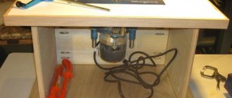
When the clamp is in place, you need to install a wood disc on the grinder. You can, of course, get by with a metal cutter, but then there will be too much smoke. It is required to make a cut in the plywood, which will be the starting point for further work, which requires clear corners.
PHOTO: YouTube.comInstalling a wood blade for cutting plywood
Measuring and setting rulers
All that remains is to turn on the grinder and cut through the plywood, simply lowering the angle grinder down.
For further work, you will need a piece of corner with two holes on one side for fixing. It must be positioned so that the undrilled edge is in the center of the cut in the plywood. The first one to mark is the hole that is closest to the cut. It will be the main one, and the rest will be “tuning”. With their help, it will be possible to subsequently set the cutting angles of the processed material.
PHOTO: YouTube.com You need to mark the first hole, which is then drilled
The nuances of drilling a hole
Initially, you need to use a 10mm drill, which should not go deeper than the width of the nut. Then you need to use a thinner drill and go right through the plywood. Now it will become clear why this should be done.
It is necessary to insert a 10mm wrench nut into the hole.
It should be flush with the surface (this is important!). It's the step inside that stops her
PHOTO: YouTube.com The hole is ready, you can drive the nut inside
Setting the corners
Now it's time for accurate measurements. You need to insert a cutting disc into the plywood slot, after which the corner should be positioned perpendicular to the grinder. A perfect 90° angle is required. Then you should mark and drill the hole farthest from the angle grinder and also hammer the nut into it. Now, if you screw in both screws, you can cut any workpiece at 90°.
PHOTO: YouTube.com A right angle of 90° is required
However, this is just the beginning of working with corners. After all, cutting is required not only at 90°. Sometimes 45° is necessary both in one direction and in the other. To ensure this functionality, you need to unscrew the screw farthest from the angle grinder and in a similar way, using a protractor or protractor, drill 2 more holes and also drive nuts into them.
You have to be extremely precise here. An error of even one degree will lead to an error in cutting parts.
PHOTO: YouTube.com Angles should be measured as carefully as possible
The frame could be considered complete, but there is a problem - if you work with metal, the plywood begins to burn, which means it needs protection.
Wall panel for storing grinders and discs
An angle grinder is a universal power tool that is constantly used both on a construction site and in the country, as well as at home. Speaking about the home use of an angle grinder, it should be noted that it must be stored so that it is always at hand.
And for this, it is best to make a wall shield, on which you can conveniently place not only the tool itself, but discs (cutting, grinding, etc.) along with a wrench for tightening the nut. Moreover, making a homemade stand will require a minimum of time and materials.
Option 2 - how to quickly and easily make a pendulum saw
If you have a welding machine and consumables, you can make a stationary machine from an angle grinder in a matter of hours. Moreover, you don’t need to buy anything for this, since the necessary tubes, fittings and profiles can be found in a garage or a pile of scrap metal. To build a simple cutting machine using an angle grinder as the main tool, you will need to use the following parts:
- Metal profiles measuring 150-200 mm
- Sleeve 10-15 cm long
- Hairpin 20 cm long and 8-10 mm in diameter
- Washers
- Metal corner
- A sheet of metal 2-3 mm thick, which will act as a base
So, to make a simple homemade product you will need to perform the following steps:
Cut the stud to the required length, then place the sleeve inside (it should move freely along the stud), and tighten the nuts onto the ends of the protruding stud. Tighten two nuts on both sides, since the second will act as a locknut. The nuts should not be screwed in completely, they should not come into contact with the sleeve. The resulting structure should be welded to a steel sheet
In this case, it is important to grab the nuts, and the sleeve must remain mobile, that is, move freely. At the next stage, it is necessary to make fastenings for the angle grinder. To do this, you will need metal profiles, as well as washers that will play the role of brackets. Cut to the required length (it all depends on the tool used, but for a low-power angle grinder, the profile length is 15-20 cm)
Weld washers to the ends of the profiles. It is recommended to use at least 2 mounts for an angle grinder, but three are better. The angle grinder has threaded holes for connecting the handle. We use these holes to attach the tool to the movable base using pre-prepared brackets. First, the brackets are attached to the tool using bolted connections of the appropriate size, and then the reverse ends of the profiles are welded to the sleeve. As a result, we get a ready-made machine that can be produced literally within an hour
The photo below shows the design of a homemade machine made from a grinder with a detailed description of the necessary materials. Using the instructions, and for some, a diagram is enough to make a homemade cutting machine
It is important to take into account that a casing for an angle grinder must be provided, otherwise the risk of serious injury increases. It is strictly prohibited to operate the tool without protective clothing, not only on a person, but also on the device itself.
The simplest device is ready for use. The angle in the machine design is used as a guide for centering cutting materials. You also need to make a straight hole in the iron sheet, into which part of the disk will “go” when sawing workpieces.
Sheet steel cutting machine
Grinder machines, which can be used to cut steel sheet material, are much more complex than conventional pendulum ones.
The main difficulty here is that the sheet of metal has certain linear dimensions and it is necessary to maintain evenness of cutting along the entire line. Another difficulty here can be considered the effect of heating the cutting area, during which the metal expands and clamps the angle grinder disk in the channel, which is fraught with jamming and rupture of the tool with all the ensuing consequences. The main parts of such a machine:
- Base. Ideally, it should be no smaller than the sheet that is supposed to be cut with a grinder, or allow the entire cutting area to be laid on it. It is necessary to use steel as a manufacturing material so that it absorbs heat, preventing the steel cutting line from overheating.
- U-shaped stand. This structural element serves as a guide for pulling the angle grinder through. The length of the section between the legs of the stand should be sufficient to place a sheet between them, plus allow the body of the angle grinder to fit freely.
- The carriage is a movable element that moves along a U-shaped stand on bearings. A pendulum console and a depth limiter for lowering the cutting disc are attached to it.
- The pendulum console serves as a mechanism for lowering the angle grinder to the level of the working position. Also attached to it is a tool control handle.
You need to pull the angle grinder in the direction opposite to the direction of the sparks, otherwise the tool will be undermined with a high probability of jamming.
The simplest stand with a stationary table
If the machine does not allow for complex cuts, the stand for the grinder can be made using a simplified version without a rotary table. That is, the tabletop is tightly welded to the frame.
Let's look at a step-by-step photo describing the manufacture of the stand:
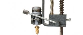
The pivot assembly will require two bearings, a threaded shaft at both ends, and a flange that can be removed from a passenger car pump. All parts mounted on the shaft are clamped with nuts. To prevent the bearings from moving, bushings are installed between them.
The hub is made from a piece of pipe with a larger diameter than the bearing race. First, the workpiece is cut off, and then this sleeve is sawed lengthwise.
Plates are welded on both sides of the cut. Holes are drilled into them so that the inserted bearings with the shaft can be firmly secured with bolts. I cut a corner to fit the plate, and drill holes in both shelves. The part is needed to mount the hinge on the bed frame.
A U-shaped bracket for fixing a power tool is bent from a steel plate 5 mm thick. Holes are drilled on the side shelves. They must coincide with the holes on the gearbox housing of the angle grinder.
A lever is welded from a profile pipe with a cross-section of 20x20 mm. It consists of a main jumper to which two elements are welded at an angle, forming the lever rods. The second end of the rods will be fixed to the hinge. I weld a U-shaped bracket onto the edge of the lintel to fix the grinder.
The frame of the bed is welded from a corner with a cross section of 32 mm. Guides from a profile with a cross-section of 20x20 mm are welded along the length of the frame. They are needed to install an adjustable stop with which the workpiece to be cut will be fixed.
The tabletop is cut out of a steel plate 3 mm thick. You should end up with two fragments. The plates can be welded or bolted to the frame.
A hinge mechanism is attached to the frame of the finished bed. The lever rods are secured to the flange using bolts. A return spring is installed between the frame and one of the lever elements. Now all that remains is to clamp the grinder in the bracket and try to make a cut, but first you need to secure the adjustable stop between the guides on the frame.
The size of any of the presented stands depends on the dimensions of the angle grinder. Here you will have to do your own calculations. It will take a couple of days to make the structure, but the homemade stand will be ideally tailored to your own requirements.
The simplest stand with a holder made from a water pipe and corners
If the previous ideas for angle grinder stands seemed too complicated for you, we offer you another extremely simplified, but no less convenient option. To make it you will need angles of different sizes, a water pipe, scraps of metal, as well as bolts and nuts for fastenings. Let's start the analysis with the platform. Its size is selected individually according to the complexity of your work and the dimensions of the workpieces. In our example, the dimensions of the metal platform are 40x27 cm. To give it rigidity and prevent slipping, we screw it to the table at the corners with self-tapping screws, and also strengthen the stand by welding the corners under it.
To attach the holder to the platform, we fix a 50x50 mm corner equal to the width of the stand. We weld another corner of the same section with a height of 17 cm to it in a vertical position.
After that, we move on to the holder itself. We find an old water pipe or other pipe with a diameter of about 25 mm, measuring its length in accordance with the dimensions of the platform and the angle grinder. To secure the cutting wheel on it along with the tools themselves, we weld two metal plates 5 cm wide and 9.5 cm long to the holder. On the edge of the pipe we weld a nut to secure the side handle, which needs to be removed from the angle grinder. This will make it easier for you to lower and raise the stand.
Separately, I would like to talk about another attachment of the holder to the vertical corner. To form a plane, we also weld a piece of a 30x30 mm corner to the stand corner and pipe. We add mobility and reliability to the connection of the holder with the frame in this part using an M-8 bolt, clamping it on the reverse side with a nut and a locknut. When raising and lowering the structure in this part of the rack, the bolt is clamped and firmly fixes the selected position of the angle grinder.
The protective casing of the angle grinder is quite rigid, which allows you to make fastenings in it. On one part we fix the plates with bolts, and on the other we make an additional attachment point for the bracket, screwing it to the place where the handle was removed. We cut the bracket 4 cm wide and 16 cm long with a small angular bevel, also about 4 cm.
The main part of the rack is assembled, all that remains is to take care of the ease of use. As in previous versions, we screw a stop from a 50x50 mm corner to the platform. For better visibility during cutting, a small upper part of the corner at the edge can be cut off. Now it will be convenient for you to clamp the workpiece with a clamp and make an even cut. Also, do not forget to paint the machine or coat the metal with enamel to improve its aesthetic appearance and extend its service life.
Instructions for making a homemade stand for an angle grinder
In general, you need to act like this:
- First of all, the corrugated pipes are cut into pieces, and then either welded or screwed with bolts. In the second case, it will be necessary to drill holes for mounting. The result is a stand in the form of a frame.
- Next, a bracket is connected to which the angle grinder will be directly attached: two holes with a diameter of 1 cm are drilled in the profile and two sections are sawn off according to the drawing.
- Then they must be attached to the stand using a cross made of two pieces, in the middle of which a hole is also drilled. A hinge axis will be installed in it.
- An M10 bolt (15 cm long) is threaded through the holes - this will be the axis. Extended nuts are welded to the profile, but so that they rotate freely.
- At the second stage, the lever is made. It can be either pendulum or stationary. The length of the tripod is calculated from the length of the grinder itself. Having made two cuts, you need to weld them to the nuts, having previously marked their position.
- A little earlier, a bracket was attached to the grinder, which now needs to be screwed to the tripod. A rotating corner element attached to the base will help with this.
- When installing an angle grinder on a homemade holder, you must strictly measure the angles with a square. The angle grinder is bolted to the stand.
- The third stage is making the guides. To do this, two more cuts are attached to the base, as well as a fixed bolt. In order for the turning angle to move, it is necessary to drill a hole in it in which the bolt will be attached.
- Holes are made in the bracket on the grinder to screw hooks into them. And as a stand for the frame, bolts screwed in from the bottom are suitable.
- A spring is attached to the hooks, the length of which must be measured in advance. Its function is to allow the grinder to stand upright after finishing work.
- At the final stage, the homemade frame for the angle grinder is tested: a test cut is made and its angle is checked.
There is nothing complicated about how to make a stand for an angle grinder yourself.
Model with a small circle
Do-it-yourself stand for an angle grinder - overview of options
The main tasks of this rack:
To attach the grinder to the console, threaded fastenings of the handle on its head are suitable. There are 3 of them, and this is more than enough for reliable fixation.
Sometimes not everyone uses them.
And sometimes, to secure the grinder, they use a protective casing that is quite rigid and securely attached to its head.
For small grinders working with discs up to 125 - 150 mm, sometimes it will be sufficient to fasten the body to the console using powerful clamps, but to prevent axial rotation of the tool, the stop pad of the grinder head must be used.
Angles that work with large-diameter cutting discs (200 - 230 mm), in addition to securely attaching them to the console, must have a good support base for attaching the console itself to the work table.
This ensures minimal deviation from the cutting plane.
Many DIYers ensure the oscillatory movement of the console by installing one or two bearings to attach it to the desktop. For this purpose, ready-made bearing units for cars or bicycles are often used. However, sufficient mobility will be provided by a simple bolted connection, the parts of which, if well lubricated, will work as ordinary plain bearings.
So, as shown in the video describing the simple design of a metal angle grinder stand:
True, we would not rely on such reliability of fixing the tool in the upper position, as the author of the video recommends, but would install the tension spring in a convenient place.
It is clear that repairing such a console mount comes down to replacing the bolt, or, in extreme cases, simply increasing its diameter or installing a bushing if the mating parts are worn out a lot.
A similar principle of ensuring compliance with the flatness of the cut is also ensured when making a stand not from corners, but from profile pipes. Watch a short video about a simple homemade metal drain for an angle grinder:
Few people decide to make a wooden stand for an angle grinder, but this does not mean that it cannot be made. But some design solutions that we want to show you may well serve as a source of ideas for creating a rack of your own design, incl. and from this material.
To enlarge the picture, click on it:
Sometimes, to ensure that the tool returns to the upper position after making a cut, instead of a tension spring, a conventional counterweight is used to compensate for the weight of the tool itself.
Option 1 - a simple way to make a cutting machine from an angle grinder
A simple way to make a homemade product involves making a base on which fixed connectors for a movable plate are attached. So, in more detail about how to make a machine from an angle grinder:
- Take a steel plate measuring 15x15 cm and at least 2 mm thick. Such a large size is needed in order to secure it to the workbench with bolted connectors. If the workbench (table) is iron, then the base can be welded to it, so in this case you can use a shorter plate 10x10 cm
- Weld two rectangular plates perpendicularly to the base, located at a distance of 5-8 cm from each other. The thickness of the plates should also be at least 2 mm. Their length depends on the size of the power tool, but usually small or medium grinders are used for stationary machines, so the length of the plates is 8-10 cm
- At the base of the plates, make a straight hole into which the connecting bolt is installed. The hole diameter is 6-8 mm, which is not so important
- At the next stage, you will need to make a movable base to which the grinder will be attached. To do this, you will need to take a steel plate at least 20-30 cm long, which depends on the size of the power tool. The width of this frame should be slightly less than the distance between the protrusions of the rectangular plates welded to the base
- On the back side of the movable plate, you need to weld a round oblong sleeve into which the connecting bolt will be placed
- It is necessary to secure the tool to the resulting movable plate using clamps, ties and other methods. The number of fasteners should be more than 2, and preferably at least three for greater safety
- Having secured the resulting structure to the workbench, you can test its operation
For ease of operation, you can weld a handle to the movable bar, and also install an auto-return spring, which will return the tool to its original position, that is, move it up. The photo below shows a ready-made installation for cutting from an angle grinder. As you can see from the example, its manufacture will require a minimum of effort and materials, and the result is a stationary device for cutting various materials.
This is interesting! Finally, you will need to cut a strip of the appropriate size in the workbench, into which the rotating circle in the tool chuck will “go” when cutting materials.
When constructing the device, do not forget that safe operation depends on how to secure the angle grinder. It should be securely fixed in 2-3 points, which will prevent it from moving during work, as well as “flying off” from the movable frame. When installing the tool on a movable bed, it is necessary that the position of the grinder be strictly at a right angle, that is, the circle must be located strictly in a vertical position.
The resulting device is suitable for processing various materials from wood to durable stone. When working with a tool, do not forget to use safety glasses, gloves, and protective clothing. Instead of a workbench, you can use a wooden or steel frame on which to realize your idea.
This is interesting! Similar simple frames for grinders are manufactured in the factory, so if you have an extra 2-3 thousand rubles, you can purchase a ready-made base and use it right today. However, there are no difficulties in making it yourself, so you need to decide on your own in each individual case which is better.
Manufacturing of main components
So, let's describe the process of assembling the frame step by step:
1. The main difficulty is the design of the rotary lever, which must securely fix the angle grinder and ensure its rotation by 90°. To do this, you can use metal corners or profile pipes with bolts screwed to them in two planes, which will provide pressure on the tool.
2. To make a hinge device, you can take three connecting rods from an old car and an axle pin. This device will have no backlash or gaps, and the hinge axis will run parallel to the table plane, ensuring cutting accuracy. Although you can assemble a swing arm from ordinary hinges.
Rotary lever assembled from connecting rods and axle pin
3. Old springs of the appropriate size will ensure smooth movement of the swing arm and return the angle grinder to its original position.
4. In order for the rotary lever to stand exactly at a right angle, we place a fitter’s angle to the already assembled structure, and using the installation tool we slightly bend the connecting rod mechanism.
Using a plumber's angle, we set the rotary lever exactly at a right angle
5. To ensure free movement of the tool in the table, we make a slot of the required size using a cutting wheel of the largest thickness. If necessary, we modify it (expand and lengthen) with a small grinder.
6. Accurate cutting of parts at angles of 45 and 90° can be ensured by screwing a steel angle to the working surface. To do this, insert the disk into the slot and mark the location of the mounting holes. By changing the location of such a device relative to the disk, it will be possible to rotate the parts at different angles. To obtain a mirror angle of 45°, you will need to prepare a hole that will be located at 135° relative to the disk.
Holes for mounting angles at 45, 90 and 135°
7. You can also attach a movable ruler with a limiter to our frame. In this case, it will be possible to trim the products as accurately as possible.
8. For ease of work, you will also need to attach a handle to the vertical stand that clamps the grinder on the side opposite the disk. You can use a long bolt with a plastic tube tightly fitted onto it.
9. To check the alignment, insert a grinder into the device and manually scroll the disk several times. If there is no beat, turn it on at low speed and try to cut a wooden workpiece. If the tool begins to vibrate, we look for the cause and eliminate it.
Read also: What does hfe mean on a multimeter
10. It is better to turn the device on/off remotely - after all, the worker’s hands are always busy. In this case, we use a magnetic starter attached to the foot pedal.
Main advantages
Quite often, home craftsmen are faced with a situation where they need to cut workpieces evenly. Despite the fact that the grinder is an indispensable tool in the household, the principle of its operation is monotonous. It can be extremely difficult to hold the weight of this unit in one hand for a long time, trying to make cuts as evenly as possible. In this case, craftsmen often have the idea to make a durable and stable support for it.
In order for the result to exceed all expectations, you need to make high-quality fasteners, as well as prepare all the necessary materials at hand: small wooden blocks and plywood. It is these details that will help to install the stand permanently on a flat plane. Having made such a holder for an angle grinder with your own hands, a specialist will no longer need to hold the tool suspended, worrying about the abrasive wheel flying out. This situation is fraught with serious injury.
The main advantages of such a rack include the following:
- The master always has the opportunity to position the grinder at the desired angle.
- The workpiece can be fixed in the most suitable position. For these purposes, a vice is used, which helps to cut workpieces of the required size.
- By making a homemade angle grinder stand with your own hands, you can quickly and accurately cut light metals: ceramic tiles, aluminum profiles, metal corners.
- In a short period of time, the master will be able to produce the required number of blanks.
- If necessary, vertical movement of parts is implemented to perform certain tasks. The main tool in this case is an angle grinder (angle grinder).
- Labor productivity increases significantly.
- The operation of such racks is characterized by a high level of safety.
- Guaranteed high degree of stability for the rotating holder.
- There is no need to hold a heavy tool in your hands.
- The risks of the grinder possibly falling out or slipping out of your hands are completely minimized.
Despite all the advantages, novice craftsmen often wonder whether a homemade machine for attaching an angle grinder will allow them to cut metal smoothly. After all, the rotation speed and frequency of this tool are simply elusive to the human eye. Of course, it is much easier to purchase a ready-made machine from a specialized store, but factory-made devices (such as Metabo) also need to be improved. After all, they are all made of thin metal, which is why they are considered flimsy and short-lived.
What may be needed to make a bed
Drawing of a metal frame
Before you start making a frame for an angle grinder, you should decide what types of work this machine will perform. A self-made angle grinder stand can be much more functional than industrial products. The type of attachment of the angle grinder to the frame is of great importance - vertical or horizontal. The depth of cut largely depends on this. The type of fastening also depends on the nature of the work performed.
To cut materials on a stationary work table, the grinder is mounted on a pendulum bracket made of angles or profiled pipes. If it is necessary to cut large sheets of steel, textolite, or plywood, then the angle grinder is mounted on a movable carriage that moves along guides made of angles or channels. Having decided on the design, you should prepare the necessary tools and materials in advance.
Tools:
- Bulgarian;
- drilling machine;
- welding machine;
- grinding wheel;
- pliers;
- Screwdriver Set;
- a set of keys;
- measuring instruments.
Materials:
- steel corner 40×40;
- steel corner 50×50;
- channel 5U or 6.5U (for guides of a moving carriage);
- water pipe cuttings;
- profile pipes 15×15, 20×20, 25×25;
- bearings;
- hardware;
- tin trim;
- textolite
Assembly of the structure
When a master decides to make a tripod for an angle grinder himself, this helps to avoid many costs, since factory models are expensive and short-lived. But a good result also depends on the presence of basic skills:
- Ability to operate an angle grinder and a household welding machine.
- Drill holes carefully.
- Have some free time and patience.
In order for the rack to meet all operational requirements, its assembly must take place in strict sequence. Depending on personal preferences, the master can develop his own drawing that will correspond to a specific model of an angle grinder, or he can use ready-made drawings. In addition, before any manipulations, you need to check the working condition of the main unit. If it works poorly and often breaks down, then there is no need to build a powerful frame for it.
Experts say that the assembly procedure for an angle grinder stand is as follows:
- Initially, you need to prepare a metal pipe, which must be carefully cut into pieces of a certain length. All manipulations must correspond to the drawing used.
- Drill small holes in the indicated places.
- At this stage, make the upper and lower frames.
- Weld metal blanks with a welding machine or screw them onto bolted joints.
- Take a pre-prepared metal sheet or chipboard.
- Depending on the diameter of the stand, cut out the working surface.
- Place the finished surface on the lower platform of the desktop.
- Secure everything with bolts.
- Attach the holder to the vertical frame so that the pendulum type of rotation is free.
- Carefully install a precise spring that will return the angle grinder to its original position every time.
- One end of the spring should be fixed on the upper part of the end, but the other end on the holder.
- It's time to take a 12 V relay, which will help increase the level of comfort when working with an angle grinder. It should be located in such a way that it is convenient to reach the button during operation.
- Carefully inspect the condition of the wiring and check its functionality.
- In the workshop, be sure to allocate a separate outlet for the bed used.
- Take high-quality paints, varnishes and primers to completely cover the created device with them. These manipulations will help give the product a completed and impressive look. In addition, a protective coating of primer will protect the rack from the negative effects of corrosion.
- At this stage, all that remains is to equip the structure with a movable ruler and a special limiter.
- Check the finished frame for operability, start the angle grinder at idle speed.
Components for assembling the stand
A homemade stand, designed for an angle grinder or angle grinder, is made with your own hands based on various drawings. Therefore, before starting work or purchasing components, carefully decide on the design that is right for you.
It is worth highlighting several main nuances of assembling the stand (bed) for your angle grinder.
- Profiled metal pipes. This is the most common material on which stands are made. The angle grinder will hold on them reliably, firmly and for a long time. The metal has all the necessary qualities to ensure durability of the rack structure. The only controversial drawback of metal is the need to use welding to connect the frame elements. Although in many cases welding is replaced by bolted connections, you will need a drilling device for the job.
- Lumber for the rack. It is not uncommon to use wood as the main material for the manufacture of the frame. This is not to say that this option is completely unacceptable. Hardwood is able to cope with increased loads and not deform throughout its entire service life. Lumber is easier to process than metal, so assembling the structure takes less time and requires minimal skills. If your angle grinder is not particularly powerful and is lightweight, you have every reason to make the frame from durable wood.
- Compound. The stand can be assembled by welding or bolted connections. The second option is more profitable because such structures are easy to disassemble if necessary.
If you have decided on the materials of the rack and the method of connecting the frame structure, prepare the following tools and materials for work:
- Chipboard or sheet of metal. This is necessary to create a working surface for the rack;
- Bolts, nuts, washers, wrenches of the appropriate size;
- 12V relay;
- A spring of decent power;
- Channel;
- Profiled pipe;
- Corners made of durable metal;
- Drill;
- Grinding machine;
- Welding device.
Assembling the rack structure
A homemade frame has the main advantage - minimal financial costs for improving the grinder. You can buy a factory model, but it doesn't come cheap. In addition, self-assembled racks often have characteristics similar to their factory counterparts.
This raises a logical question: why pay for something you can do yourself?
But a homemade bed makes certain demands on the master. He must:
- Have minimal experience;
- Have skills in working with angle grinders;
- Drill carefully;
- Operate a welding machine;
- Have enough time to complete the work to improve the grinder;
- Be patient in case something goes wrong and the rack design has to be redone.
If all this is there, then all that remains is to follow the instructions for assembling the rack.
- Develop a detailed drawing of the rack, or use ready-made drawings of the frame. It is preferable to adapt the design specifically to yourself and your model of angle grinder, since this way you will be able to assemble the most comfortable, ergonomic frame.
- Study the factory models of stands for angle grinders. They can be developed for specific angle grinders or be universal. This is an important point when purchasing an auxiliary structure for an angle grinder.
- Check the current condition of the grinder. There is no point in using an old, poorly functioning angle grinder when constructing a bed. It is better to leave it for rough manual processing of workpieces, and install a new, efficient and productive grinder on the frame.
- To assemble a simple frame for an angle grinder, you will need two frames and a holder.
- Cut pieces of the metal pipe to the required length according to the rack drawings, and make holes at the required points.
- Use a welding machine to make frames - upper and lower. Welding can be replaced by bolted connections, although in this case reliable welding will be preferable.
- Cut out a work surface from a metal sheet or chipboard. For powerful grinders, preference is given to metal tables, and for light angle grinders, a sheet of chipboard will be sufficient.
- Install the lower frame on the platform (work table), after which the upper frame is welded or bolted to it.
- The holder is fixed to the vertical frame with bolts. Make sure that the holder can rotate freely like a pendulum.
- Install a strong spring. This element will allow you to return the angle grinder to its original position. Fix it with one end of the spring on the upper end of the vertical frame, and the other end is installed on the holder. Over time, the spring can stretch and wear out, which is a natural phenomenon. Therefore, during active use, you will need to periodically change the spring.
- To increase the level of comfort when working on an angle grinder with a stand, use a 12 V relay to connect the switch button. Through this element, power will be supplied to the device. This way you won’t have to reach for the button on the grinder every time.
- Make sure that the wiring is in good condition and allocate a separate outlet for the machine. Your own machine is not necessary here, but you should not operate the machine through an extension cord to which other consumers are connected.
- Use a metal primer, varnishes and paints to give the angle grinder frame a finished look. This will protect the structure from rust and will allow you to receive aesthetic pleasure from the completed rack.
- Add a movable ruler and a limiter to the design. With their help, you will increase the accuracy of workpiece processing.
Read also: Injection gas burner drawing
Check the functionality of the frame for the angle grinder only at idle after completing the assembly work.
It is better to secure a massive grinder in a rack. With the help of such a machine it will be possible to cut parts of the same type or parts with a large surface area with greater accuracy. It doesn’t always make sense to buy a ready-made frame - they often have insufficient rigidity, and it will not be possible to securely secure the angle grinder in them. It is much easier to assemble it yourself from durable metal corners or scraps of water pipes.
Industrial bed designs
A stand for an angle grinder will be required in the following cases:
- A structure made of difficult-to-cut material or with a large surface area is being cut/grinded.
- Increased cutting accuracy is required.
- It is necessary to process several products with the same parameters.
- The workpiece material is not continuous in cross-section, and the presence of voids and cavities can provoke vibration, shock and, consequently, sudden movement of the machine body.
The frame for the grinder is produced by almost the same companies that produce the tool itself. The price for the simplest design, depending on its manufacturer, does not exceed 2500...3000 rubles, but with increasing functionality, the price of the frame increases to 20,000...25,000 rubles, and not every home craftsman can afford such costs. In addition, such racks are not particularly versatile, and, of course, do not take into account the individual needs of the user.
Such beds consist of the following elements:
- A base plate, which is made of thick sheet steel and is equipped with T-shaped slots for fastening the workpiece. It may also be a cast iron stove;
- The actual rack, on which a mounting device is provided for an angle grinder of a specific model;
- Adjustment devices that allow you to rotate the stand itself, as well as change the vertical position of the angle grinder;
- Optional: clamps or clamps for workpieces, the dimensions of which are unified with T-slots. Sometimes the kit also includes a bench vice with a set of profiled stands;
- A rotary handle, with the help of which the working movement of the grinder itself is performed;
- Measuring devices, usually an angular or regular ruler;
- Particularly advanced models also have a return mechanism with a spring.
Positive features include the ability to cleanly cut pipes from round profiles, which is problematic and even dangerous without stable clamping of the workpiece. The grinder bed is also necessary for corner cuts of any profile.
The technical capabilities of these devices depend on the area of the supporting surface of the plate and the lifting height of the angle grinder in the frame. Typically, the parameters are calculated for a grinder disc with a diameter of up to 250 mm, and for the size of the fixed part of the workpiece no more than 100...150 mm.
Required design elements
Among experienced craftsmen, there is a universal copy of the bed, which consists of several parts:
- Return mechanism.
- A support frame that can later be installed on any flat surface or even a workbench. To manufacture this system unit, you can use profile pipes that have increased rigidity and are well resistant to possible vibrations.
- A durable table, which must be made of thick sheet metal with all mounting holes.
- Convenient swivel lever with tool holders.
- A high-quality universal prefabricated device of a round shape, which is equipped with 9 mm grooves. These devices will be able to support a tool whose weight does not exceed 10 kilograms. A rotary table with a screw control mechanism (reading dial and handwheel) is installed on the USP. Experts say that a regular hub from any passenger car can be used as a turntable. All dimensions must be taken into account.
- A vertical stand to which the grinder itself will be attached.
- High-quality vice for fixing workpieces. It is worth considering that this device should be installed cantilevered, so that in the future it will be possible to balance the overturning moment that comes from the USP.
- For comfortable work, the turntable can be equipped with a regular ruler, which will measure all linear as well as angular movements. Instead of a factory line, you can use a home-made device, which must correspond to the parameters specified in the drawing. In order to properly make a desktop at home, you need to provide in advance for radius fastening of the corners. The moment when it is possible to move the bench vice without disturbing the overall alignment is considered mandatory.
Making a homemade machine from a grinder features
It’s not difficult to make your own machine from a grinder yourself. Moreover, there is a wide variety of manufacturing options, which depends on the available materials and imagination. There are two types of stationary cutting machines made from grinders:
- Simple - it received this name for one reason, which is not only the ease of manufacture, but also the minimalism of the device itself. The tool is attached to the workbench using additional materials, and it can be used
- Complex - it is rational to manufacture such machines if you plan to use it often for different actions. In most cases, a simple device is enough for a home garage, the manufacture of which requires little time, effort and consumables.
In order to make a cutting machine from a grinder with your own hands, you will need consumables, which are metal plates, as well as profiles and fasteners - bolts, nuts and washers. The only specialized tools you will need are an electric drill and a welding machine. Let's look at how to make the simplest version of a cutting machine from an angle grinder in more detail below.
Why make a machine from an angle grinder
A cutting machine is a useful and necessary thing, not only in industrial conditions, but also in the household. With this useful tool you can make precise cuts of parts and workpieces. This is achieved by securely fixing the cutting disc, into the spindle of which you can install not only abrasive wheels for cutting metal. A stationary machine can be used for cutting tiles, bricks, marble, granite and other similar materials, using special diamond-coated wheels in the design of the tool. If necessary, such a machine can be used for sawing beams, boards and other wood workpieces.
Many people who have repeatedly faced the need to make an accurate cut of a workpiece want to know how to make their own cutting machine from an angle grinder and available materials. Holding the grinder in your hands, you can also make a precise cut, but it is more difficult to do this, since you have to hold the tool exclusively with both hands. Using a homemade cutting machine, you can not only perform, but also simplify the following work:
- Cut sheet material, such as galvanizing, used for chimney insulation and other purposes
- Cut ceramic tiles and tiles - keep in mind that the cut can only be made straight
- Cut materials at different angles
- Cut a metal profile, pipe, wooden beams, boards, etc.
The manufacture of a machine from a grinder requires an appropriate approach. After all, the tool itself is very dangerous, so the slightest miscalculation can lead to the master being seriously injured. The consequences of working with an angle grinder if safety regulations are not observed are known, so first, before building a homemade product, it is worth noting the following:
- Only with the correct manufacture of a stationary cutting machine can you be confident in its reliability and safety
- If you plan to do it, then you need to calculate every step so that no disaster happens during operation.
- Using a machine is in some ways safer than using a tool while holding it in your hands. However, you need to be aware that an angle grinder is a mobile tool, and making a homemade one is already a violation of safety regulations
- For manufacturing, it is necessary to use materials of appropriate reliability, corresponding to the power and size of the main power tool.
Having dealt with the need to manufacture the machine, you can get down to business.
This is interesting!
If you can’t decide whether it’s better to buy a new machine or make it yourself, then the second option is more preferable, since the cost of a factory device will cost at least 10,000 rubles. If you make it yourself, you won’t need any expenses, since the grinder is already on the household, and the components can be found in the garage.
Do-it-yourself metal cutting machine: recommendations for creating
Disc cutting machines are tools whose design is based on a special platform or frame made of metal. The machine itself is equipped with parts that ensure reliable fixation of the material in a certain position at the required angle during the cutting process.
A disk made of high-speed steel is used as a cutting element in such structures. It is also called carbide. A wheel coated with an abrasive material can also be used for cutting metal. The cutting element is driven by an electric motor with a belt or gear drive.
Diagram of a pendulum-type metal cutting machine
Note! In low-power versions of the tool, it is possible to use a cutting element mounted directly on the shaft of an electric motor. In other cases, using the disc in this way can be dangerous.
In disk machines, there are three different feeds of the cutting component:
- lower;
- pendulum;
- frontal.
Depending on the number of cutting elements, machines are:
- single-head - only one cutting disk is included in the device package, so if it is necessary to change the operation, the cutting edge is readjusted in accordance with the new task;
- double-head - the design makes it possible to work with two tools at once, thereby increasing efficiency. In such machines, one head is in a fixed position and remains stable, while the second head can move. Double-head designs can carry out work automatically.
An example of a DIY metal cutting machine
Making a disc cutting machine for metal with your own hands: procedure
When manufacturing a machine designed to work with metal, the actions are performed in the following order:
- Protective covers are being prepared that will be installed on the drive belt, as well as the cutting disc.
- The motor is installed. The drive belt acts as a connecting part between the cutting element shaft and the engine.
- A shaft is made on which the drive pulley will be attached, and a cutting disc will be installed. The unit is subject to assembly and subsequent installation on the pendulum. In this case, the movable upper part of the structure plays the role of a pendulum, where the cutting element and motor are located.
- A shaft is made to mount the pendulum.
- The frame for installing the machine is being made. The spark arrester and the workpiece will be attached to it.
- The pendulum is installed on the frame.
- Electrical wiring is being installed.
- A test run of the tool and adjustment of the equipment is carried out.
As a cutting element in homemade cutting machines, a disk made of high-speed steel or a circle coated with an abrasive material is used.
Calculation of a pulley for a homemade metal cutting machine
The calculation of the diameter of the pulleys is carried out taking into account the rotational speed of the disk and other parameters. Assuming that the motor power is at least 300 W, the rotational speed of the disk will be at least 3000 rpm, and its diameter will be 40 cm.
Helpful advice! During the process of cutting metal, the nut in the disk fixation area may come loose. To avoid this, it is recommended to place the drive pulleys on the left side, and the disk itself on the shaft on the right.
Typically, discs are marked by the manufacturer, who marks the product with the maximum permissible rotational speed value. In this case, the indicator is 4400 rpm. Therefore, you can select any speed within the range of 3000-4400 rpm.
Data for calculations:
- rotational speed of the motor – 1500 rpm;
- the diameter of the pulley intended for installation on the shaft is 6.5 cm;
- rotational speed of the disk – 3000 rpm.
Drawing of a frame-type cutting machine (frame dimensions depend on the size of the tool used)
The calculation is performed in the following sequence:
- Set the length of the shaft around the perimeter. To do this, multiply the number π, which is equal to 3.14, by the diameter size: 3.14 x 6.5 = 20.41 cm (shaft length around the perimeter).
- The resulting value is multiplied by the required number of revolutions: 20.41 x 3000 rpm. = 61230 cm/min.
- The result must be divided by the number of engine revolutions: 61230 cm/min/1500 rpm. = 40.82 cm (perimeter motor pulley length).
- The resulting value is divided by the number π: 40.82 cm/3.14 = 13 cm (required pulley size).
Calculating the length of the belt for a homemade metal cutting machine with your own hands
To perform these calculations you will need the following data:
- drive pulley parameters (radius);
- the distance separating the center points of the pulleys;
- parameters of the driven pulley (radius).
Having 2 pulleys with dimensional parameters of 13 cm and 6.5 cm, you can make the necessary calculations. Since the distance between the centers of these elements can be changed (since it is necessary to bring the belt into a state of tension), a segment 50 cm long will be taken as an example.
The larger the diameter of the cutting element, the easier it will be to cut thick metal
Now you need to calculate 1/2 the circumference of each pulley. Since the drive belt runs between them twice, double the distance between the center points must be added to this value.
First pulley (circumference):
3.14 (number π) x 3.25 cm = 10.20 cm
Second pulley (circumference):
3.14 (π number) x 6.5 cm = 20.41 cm
Drive belt (required length):
20.41 cm + 10.20 cm + 50cm x 2 = 13.06 cm
Helpful advice! To get a more accurate result, you should make calculations with the maximum and minimum distance between the central points of the pulleys and select the average value.
To make your own machine design for working with metal, you should prepare the necessary tools.
Drawing of a pendulum-type cutting machine: on the left - dimensions of the base, on the right - design features of the pendulum
The required set of tools and materials includes:
- welding machine;
- metal corner (steel);
- channel and chain;
- button to turn on/off;
- bearings;
- shaft and electric motor;
- electric drill;
- sheet steel to create a working surface;
- box for placing the electrical components of the machine.
Principles of creating a machine for cutting metal
The manufacturing scheme for a homemade machine is subject to certain principles; they must be taken into account before getting down to business:
- It is very important to choose the right gear and install it. The preservation of torque and its correct transmission from the engine to the cutting element (disc) depend on this component;
- It is imperative to provide a vice. This tool makes work more comfortable and also increases the degree of safety;
The presence of a vice increases the level of comfort and safety when working with a homemade machine
- selection of the optimal cutting angle. The acceptable range is 45-90°. In most cases, experts prefer cutting at right angles;
- The diameter of the cutting disc is selected taking into account what materials the master will work with on this machine in the future. The larger the diameter of the cutting element, the easier it will be to cut thick metal;
- When designing and drawing up drawings, indicators such as the dimensions of the future machine and its weight must be taken into account. These values are directly influenced by the materials from which the equipment will be made. The layout of the parts also matters.
Note! When drawing up drawings, special attention should be paid to vibration supports that are installed on the legs.
Assembling a metal frame for a cutting machine
After all the tools have been prepared and the drawings have been selected, you can proceed directly to the process of creating the machine. Using a steel angle, it is necessary to make the frame part of the structure. In accordance with the drawings, which you can draw up yourself or find on the Internet, frame elements are cut out. All of them are connected to each other by welding. First you need to check the size suitability.
The process of creating a frame for a metal cutting machine
A channel is welded to the top of the frame - it will become a guide element and will serve as the basis for further installation of the cutting component on the machine. This channel will become a kind of connecting link between the electric motor and the cutting element. After this, vertically located racks are secured to it using bolts.
It will be necessary to weld the structure of another frame. Dimensional parameters are selected individually, taking into account the dimensions of the electric motor and its features. When choosing an electric motor for a machine, it is better to pay attention to asynchronous type modifications. This type of equipment is characterized by increased reliability and durability.
There is one subtlety when choosing a motor. The more powerful the engine, the smoother the drive will move.
Assembling the electrical components for the machine
Installation of equipment involves mounting and connecting the working shaft to the electric motor of the machine. The way in which this can be done is not fundamental. If the drawings contain instructions for performing this procedure, it is better to follow them, since the correct operation and reliability of the tool depends on the quality of installation.
For homemade cutting machines, it is better to use asynchronous electric motors
Helpful advice! Some parts that you cannot make yourself can be ordered from a turner. These include flanges for fixation, as well as a pulley.
To fix the motor on a metal frame, it is better to use a bolted connection with nuts. It is recommended to place a box near the engine where the switch and electrical circuit are located, as well as the remote control for controlling the tool.
It is better to place the channel, intended for fixing the cutting disc, on a spring. You need to make sure that when you release it, it returns to its original place. To secure the spring, you can take bolts and a clamp.
The electrical component is the most important part of the tool. Be sure to include in the design a starting circuit, as well as a button for emergency shutdown of the machine. It is necessary to achieve such an arrangement of parts in which the electric motor will be connected to electricity through an automatic machine and gearbox, and not directly. A three-way starter will be enough to turn on and fully start the engine. It will also power the shutdown button.
Finally, it is worth taking care of the presence of protective devices that will protect a person during the work process. To do this, you need to make a protective casing. It will prevent sparks and small metal particles from getting into your eyes.
A protective cover is a prerequisite for working with a self-made metal cutting machine, protecting your eyes from sparks and small metal particles
Should I buy or not?
Finding a ready-made machine on store shelves that at first glance satisfies your needs is a fairly simple task. But it is unlikely that there will be a design made entirely in accordance with your requirements, and they are different for everyone. In such cases, owners of machine tools try to improve or remodel them, but are faced with very serious obstacles - either the manufacturers made the machine from alloys that are very difficult to work with by welding, or they did not take into account the little things that you need specifically - for example, an accurate ruler or a more elastic spring. Remaking someone else's is much more difficult than making your own.
Scope of application of cutting machines
Cutting disc machines are widely used in metalworking, mechanical engineering, woodworking and furniture industries. The units have also found their application in the household: they are used as a convenient tool for performing various tasks in the workshop and garage. The cutting machine is convenient to use to solve a number of problems:
- dividing the metal profile into segments of the required length;
- cutting sheet metal;
- obtaining a large number of similar blanks in a short time;
- cutting ceramic tiles;
- cutting parts at any angle, obtaining cuts of the required length, depth, and so on.
Using a homemade cutting machine you can solve a wide range of problems
The advantages of disc cutting machines include convenience and ease of use, high cutting speed and accuracy, and the ability to replace the cutting disc in a matter of minutes.
Due to their relatively low cost, universal units have a quick payback period, so they are profitable to use in small industries and small workshops.
In the household, a cutting machine is used irregularly, so purchasing a factory-made tool is irrational . It is better to make a special stand for an angle grinder. This will increase the versatility of the grinder, turning it into a small-sized cutting machine.
Safety rules when working with a homemade machine
Since an angle grinder generates a lot of noise when cutting metal, it is necessary to ensure that there are no flammable materials nearby. The side where the spark will be directed must be protected with resistant sheet metal.
When working on a homemade machine, it is mandatory to install protection, since parts of the disk can fly off in any direction. This protective part also stops circular sparks from the disc.
When making a machine, it is necessary to take into account that sparks should fly from a person, and not towards him, that is, it is necessary to secure the angle grinder with the correct side. But even in this case, it is important to wear protective clothing, glasses, and gloves.