A drilling machine for printed circuit boards belongs to the category of mini-equipment for special purposes. If desired, you can make such a machine yourself using available components. Any specialist will confirm that it is difficult to do without the use of such a device in the production of electrical products, the circuit elements of which are mounted on special printed circuit boards.
Simple mini PCB machine
General information about drilling machines
Any drilling machine is necessary in order to ensure the ability to efficiently and accurately process parts made from various materials. Where high precision processing is required (and this also applies to the process of drilling holes), manual labor must be eliminated as much as possible from the technological process. Similar problems are solved by any drilling machine, including homemade ones. It is practically impossible to do without machine equipment when processing hard materials, for drilling holes in which the efforts of the operator himself may not be enough.
Design of a benchtop belt driven drill press (click to enlarge)
Any drilling machine is a structure assembled from many components that are securely and accurately fixed relative to each other on a supporting element. Some of these nodes are rigidly fixed to the supporting structure, and some can move and be fixed in one or more spatial positions.
An example of motors used in the manufacture of a homemade mini drilling machine
The basic functions of any drilling machine, through which the processing process is ensured, is the rotation and movement in the vertical direction of the cutting tool - the drill. On many modern models of such machines, the working head with the cutting tool can also move in a horizontal plane, which allows this equipment to be used for drilling several holes without moving the part. In addition, automation systems are being actively introduced into modern drilling machines, which significantly increases their productivity and improves processing accuracy.
Below, as an example, are presented several design options for homemade drilling machines for circuit boards. Any of these diagrams can serve as a model for your machine.
Design
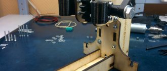
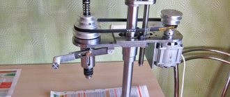
The basis of the mini drilling machine frame was a stand for carrying out linear measurements with a digital indicator with minor modifications. The stage with adjusting screws was dismantled and part of the movable rod for attaching the dial indicator to the length of the slot was removed.
At the base of the stand, two holes are drilled for mounting the table and an M4 thread is cut into them. In the rod itself, in the center of symmetry with a 15 mm indentation from the edge of the cut, a hole with a diameter of 10 mm was drilled for a guide bolt.
After preparing the base, you can begin to manufacture parts. The table is made of duralumin and has dimensions of 100×120 mm with a thickness of 15 mm. It can be made from almost any material, aluminum, iron, fiberglass, chipboard, hard wood. Choose the size of the table at your discretion. The table is attached to the base of the mini drilling machine with two M4 screws with countersunk heads.
The next part of the mini drilling machine is the movable plate in which the motor is mounted. The plate is made of duralumin, 50 mm by 130 mm in size, 15 mm thick. The thickness is not critical, it can be from 5 mm or thicker. The narrow ends of the plate are rounded with a radius of 25 mm for aesthetics. At a distance of 80 mm, two large holes are made in the plate. One for sliding on a stand while drilling with a diameter of 30mm, and the second for securing a motor with a diameter of 36mm. Between the large holes, along a line passing through their centers, another hole was drilled, in which an M10 thread was cut. The center of this threaded hole, when the plate is placed on the post, should line up with the hole drilled in the rod.
It was possible to secure the engine in the plate by simply clamping it on both sides with screws into the drilled threaded holes, but I wanted to do better. A slot was made in the plate and the engine was secured by crimping the plate using an M5 screw. Thanks to this solution, the motor is easily removed from the plate and the mini drilling machine turns into a miniature hand drill, which is sometimes necessary. If the need for a mini hand drill is frequent, then you can install a wing screw.
The next part is a lever handle, which ensures the drill stroke during drilling, which is about 7 mm. The lever handle is a duralumin plate with a thickness of 5 mm and overall dimensions of 50×120 mm. There is one large oval hole made in it, of a size that allows the motor of a mini drilling machine to pass without touching and the ability to look at the entry point of the drill into the part when drilling for aiming.
You will also need a bolt 60 mm long with a thread at the end of a length equal to the thickness of the plate of a mini drilling machine, a Morse taper A1 for attaching the chuck to the motor shaft and a spring of sufficient rigidity to return the plate with the motor to its original state.
Features of equipment for drilling holes in printed circuit boards
A machine for drilling printed circuit boards is one of the types of drilling equipment, which, given the very small size of the parts processed on it, belongs to the category of mini-devices.
Any radio amateur knows that a printed circuit board is the base on which the components of an electronic or electrical circuit are mounted. Such boards are made from sheet dielectric materials, and their dimensions directly depend on how many circuit elements need to be placed on them. Any printed circuit board, regardless of its size, simultaneously solves two problems: accurate and reliable positioning of circuit elements relative to each other and ensuring the passage of electrical signals between such elements.
Depending on the purpose and characteristics of the device for which the printed circuit board is created, it can accommodate either a small or a huge number of circuit elements. To fix each of them in the board, you need to drill holes. Very high demands are placed on the accuracy of the location of such holes relative to each other, since it is this factor that determines whether the elements of the circuit will be positioned correctly and whether it will be able to work at all after assembly.
Drilling holes in foil getinaks on a homemade machine
The difficulty of processing printed circuit boards also lies in the fact that the majority of modern electronic components are miniature in size, therefore the holes for their placement must have a small diameter. To form such holes, a miniature tool (in some cases even micro) is used. It is clear that it is not possible to work with such a tool using a conventional drill.
All of the above factors led to the creation of special machines for forming holes in printed circuit boards. These devices have a simple design, but can significantly increase the productivity of this process, as well as achieve high processing accuracy. Using a mini-drilling machine, which is easy to make with your own hands, you can quickly and accurately drill holes in printed circuit boards intended for assembling various electronic and electrical products.
Drilling machine from an old microscope
Which material to choose
Novice craftsmen are accustomed to thinking that working with wood is much easier. In case of an error, the defective material can be used for fuel or small parts or crafts can be made from it. Therefore, wooden structures are increasingly used in amateur models.
However, it is worth understanding that such machines do not provide adequate accuracy. That is why specialists use exclusively metal. Popular myths that wood is much less susceptible to mechanical damage and deformation are easily dispelled by statistical figures and reviews from experienced craftsmen.
How does a machine for drilling holes in printed circuit boards work?
The machine for forming holes in printed circuit boards differs from classic drilling equipment in its miniature size and some features of its design. The dimensions of such machines (including homemade ones, if the components for their manufacture are correctly selected and their design is optimized) rarely exceed 30 cm. Naturally, their weight is insignificant - up to 5 kg.
Design of a homemade drilling machine
If you are going to make a mini drilling machine with your own hands, you need to select the following components:
- supporting frame;
- stabilizing frame;
- a bar that will ensure movement of the working head;
- shock absorbing device;
- handle for controlling the movement of the working head;
- device for mounting an electric motor;
- the electric motor itself;
- power unit;
- collet and adapters.
Drawings of machine parts (click to enlarge)
Machine console drawing
Let's figure out what all these components are for and how to assemble a homemade mini-machine from them.
Structural elements of a mini drilling machine
Do-it-yourself mini-drilling machines can differ significantly from each other: it all depends on what components and materials were used for their manufacture. However, both factory-made and home-made models of such equipment work on the same principle and are designed to perform similar functions.
It will be easier to make the machine if you take a slide from a computer drive for the drilling head
The supporting element of the design of a drilling machine for printed circuit boards is the base frame, which also ensures the stability of the equipment during the drilling process. Based on the purpose of this structural element, it is advisable to make the frame from a metal frame, the weight of which should significantly exceed the total mass of all other equipment components. If you neglect this requirement, you will not be able to ensure the stability of your homemade machine, which means you will not achieve the required drilling accuracy.
The role of the element on which the drilling head is mounted is performed by a transitional stabilizing frame. It is best made from a metal strip or corners.
Drive carriage with attached homemade corner for the engine
The bar and shock-absorbing device are designed to ensure vertical movement of the drilling head and its spring-loading. Any structure can be used as such a bar (it is better to fix it with a shock absorber) (the only important thing is that it performs the functions assigned to it). In this case, a powerful hydraulic shock absorber can come in handy. If you don’t have such a shock absorber, you can make the bar yourself or use spring structures removed from old office furniture.
The vertical movement of the drilling head is controlled using a special handle, one end of which is connected to the body of the mini-drilling machine, its shock absorber or stabilizing frame.
Lever attachment
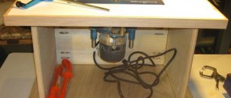
The engine mount is mounted on a stabilizing frame. The design of such a device, which can be a wooden block, a clamp, etc., will depend on the configuration and design features of the remaining components of the drilling machine for printed circuit boards. The use of such a mount is determined not only by the need for its reliable fixation, but also by the fact that you must bring the electric motor shaft to the required distance from the movement bar.
Choosing an electric motor that can be equipped with a mini-drilling machine that you assemble yourself should not cause any problems. As such a drive unit, you can use electric motors from a compact drill, cassette recorder, computer disk drive, printer and other devices that you no longer use.
Hair dryer motor
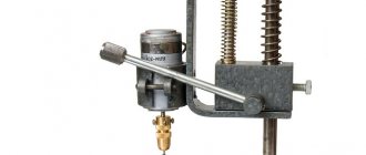
Depending on what kind of electric motor you found, clamping mechanisms for fixing drills are selected. The most convenient and versatile of these mechanisms are the chucks from a compact drill. If a suitable cartridge cannot be found, you can also use a collet mechanism. Select the parameters of the clamping device so that it can hold very small drills (or even micro-sized drills). To connect the clamping device to the motor shaft, it is necessary to use adapters, the dimensions and design of which will be determined by the type of electric motor selected.
Miniature collet chuck
Depending on which electric motor you installed on your mini-drilling machine, you need to select a power supply. When making this choice, you should pay attention to the fact that the characteristics of the power supply fully correspond to the voltage and current parameters for which the electric motor is designed.
Diagram of automatic speed control depending on the load for a 12 V engine (click to enlarge)
Fastening the guide rails
The profile rail was based on ready-made steel guides from an old radio-electronic device with removable blocks. They were chosen because:
- made of durable metal;
- have identical corners to ensure uniform distance from the vertical post;
- easy to mount.
I planned their placement on the rack and drew a line with a pencil along the square.
I made a cut along it with a hacksaw to install the clamps.
I adjusted the profiles with hammer blows.
I secured it with screws, ensuring an even gap between the corner and the bar.
The procedure for assembling a homemade device
As practice shows, it is most convenient to assemble a homemade machine for drilling holes in printed circuit boards in a certain sequence. You must act in accordance with the following algorithm.
- The frame is installed, and legs are attached to its underside, if they are provided for in the design.
- A movement bar and a holder frame on which the drilling head will be mounted are attached to the assembled frame.
- The holder frame is connected to a shock absorber, which is also fixed to the equipment frame.
- A handle for controlling the movement of the drilling head is installed, connected to a shock absorber or holder frame.
- An electric motor is mounted, the position of which is carefully adjusted.
- A collet or a universal drill chuck is attached to the shaft of the drive motor using adapters.
- A power supply connected to the electric motor via electrical wires is being installed.
- A drill is installed in the chuck and securely fixed in it.
- The assembled homemade machine is tested by trying to drill a hole in a dielectric sheet with its help.
To ensure that your homemade mini-drilling machine can always be disassembled and modified, it is best to use bolts and nuts to connect its structural elements.
If you want to make your own mini-equipment for making holes in printed circuit boards, you can always use the drawings and advice of those who already own such a machine and are actively working on it in their home workshop.
Practical examples of a homemade lathe, taking into account the recommendations outlined above
Let's start with the simplest option, which can be made in one weekend with virtually no financial costs (you already have a drill, its cost is not taken into account).
A set of blanks in the illustration: the tool itself, several wooden blanks, fasteners.
The most crucial moment is the alignment of the drill shaft with the support tip of the improvised tailstock. Therefore, we take measurements with an accuracy of up to a millimeter.
Since the machine will not be very large, we place it on a bed made of thick plywood. The holder for the drill neck is also cut out of plywood, and the clamping clamp is not necessary. A fixing screw will be sufficient. We place the nodes on the bed:
A spindle is not required: thin workpieces can be clamped in a standard drill chuck, and for larger parts an improvised washer can be made.
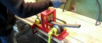
On such a machine you can easily process wooden blanks, as well as blanks made of composite materials: textolite, etc.
Using similar materials (only thick textolite is better than durable multi-layer plywood), you can make a machine that is more complex in terms of settings.
The drill itself is fixed not only in the neck area, but is also supported by an additional bracket. This will avoid vibrations, especially with high loads or unsymmetrical workpieces.
Taking into account the possibility of precise adjustment of components to a specific drill, it is possible to perform the fastening as gentle as possible for the tool itself. For example, ventilation openings should not be covered.
The support for the incisors (even if they are held in the hands) is movable. And both horizontally and vertically. During processing, the blank becomes thinner, and the supporting surface can be moved closer to the part.
The tailstock is not vertically adjustable, this is logical. And horizontally, rough adjustments are made (the support is moved), and fine adjustments are made using a screw.
The main principle of any such design is that you do not permanently lose the power tool itself. That is, the drill can be dismantled at any time and used for its intended purpose.