If you set a goal and assemble a milling machine with your own hands, you can get at your disposal an effective device that allows you to perform many technological operations on metal and other materials. Serial models of such equipment have long been well known; they are actively used at most manufacturing enterprises operating in various industries. These machines are distinguished by their wide functionality, which allows them to process workpieces made of metal, wood and a number of other materials.
An example of a DIY milling machine
Knowing all the advantages of such a device, many home craftsmen are wondering how to make a milling machine using available and inexpensive components. It should be said right away that it is possible to manufacture such a machine; moreover, it is possible to additionally provide it with functions that are inherent not only in milling, but also in turning equipment.
The simplest to use is a vertical milling machine. You can assemble it using a hand drill, spending very little time and effort. In order to make a more functional mini-milling machine for your home workshop with your own hands, you must find other components and have a lot of time, but this task is completely solvable.
When planning to make a milling machine for metal and wood with your own hands, it is very important to pay attention to the fact that the device should work on the same principle as serial equipment. To comply with this important requirement, you can familiarize yourself with the drawings of serial equipment and watch a video of the operation of a factory machine.
Milling tables are often called milling machines, but their designs are fundamentally different
A milling table is often called a milling machine. We will look at its structure at the end of this article. But a separate detailed article is devoted to the manufacture of a homemade milling table, which can be found by clicking on the link below.
More details here: DIY milling table
Tasks of milling equipment
Those who often work in their home workshop often have the need to process various products made from wood and metal. Not all operations with such products can be performed with only hand tools; this often requires special equipment. Of course, you can contact a workshop, but you will need to pay for the services it provides.
It is in such situations that a home milling machine can help out; it is quite possible for anyone who knows how to work with their hands to assemble it. Having become the owner of such equipment, it will be possible to process workpieces made of both metal and wood. Depending on the availability of certain components at your disposal, you can make either a simple homemade metal milling machine or a more complex device that already belongs to the turning and milling category.
Compact mini milling machine made at home
As mentioned above, the simplest mini-machine is assembled on the basis of a conventional drill. The operating principle of such equipment is similar to the functioning of serial machines of this type. Despite the fact that the functionality of a mini-machine made on the basis of a drill is somewhat more modest than that of more complex home-made equipment, there is always a use for such a device in any home workshop.
In order to make a more functional and complex desktop machine with your own hands, you will need a powerful electric motor, as well as a whole list of specific components. Such a machine, assembled according to all the rules, will allow you to perform quite complex technological operations at home: cut out products of complex configurations from metal and wood, process curved surfaces, select grooves, folds, splines, and much more.
Before making a milling machine with your own hands, you should study the operating principle of serial equipment, watch a video of its operation, draw up a drawing, and prepare the required components and tools that will be needed to assemble your home machine.
How to make a router from a grinder?
The first version of the router that we will consider is made from an angle grinder. First, we will provide a list of materials and tools that will be required to create it, and then directly the instructions for its manufacture.
Tools and materials
If we talk about materials and tools, you will need:
- small angle grinder with a 125 mm wheel;
- a pair of discs – stripping and trimming;
- vice;
- emulsion coolant;
- chalk;
- M14 type tap;
- a piece of sheet iron that is about 1.5 millimeters thick;
- a piece of I-beam 18 cm with a length of 200-250 millimeters or a sheet of iron 5 mm thick;
- a pair of elongated nuts, as well as a pair of regular nuts that have a diameter of 8 millimeters;
- a pair of bolts with characteristics 8 by 40 mm;
- drills 0.8 and 1 centimeter;
- a pair of bolts 8 by 10 mm;
- cord brush for an angle grinder that has metal bristles;
- drill chuck with a threaded connection measuring 1.5-13 millimeters;
- a round crown with a diameter of 4 centimeters for making holes;
- a pair of clamping bolts equipped with wings measuring 8 by 20 mm;
- a pair of 8mm nuts;
- 10 centimeters of square pipe 2.5 by 2.5 centimeters, as well as half a meter of profile 2 by 2 centimeters.
In addition, you will need drawings of the device. They can be found on the Internet or in specialized literature.
Step by step diagram
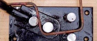
So, in order to make a manual wood router, we will first need to make a sole for it. To do this, you will need to take an iron sheet of 5 mm thickness to ensure the rigidity of the future structure, you will need to cut a piece measuring 12 centimeters, then clamp it in a vice and sand it well with a cord brush. Then all that remains is to place the plate using chalk according to a pre-created pattern.
Then, in a vice, you should carefully cut out the metal using a cutting-off disc, without going beyond the intended contours. To bring everything according to the markings, you should use a cleaning disk. After this, the part will be ready. It will be the basis of everything.
- Now you need to make a mount for the grinder itself. To do this, use a crown to make a hole with a 4-centimeter diameter in the remaining part of the metal plate. This can be done using a hammer drill, having first switched it to drilling mode.
- The metal here itself is thick, and in order to avoid seating of the crown, you should add emulsion coolant, which consists of oil and water, from time to time. The part itself should be held with a clamp. The work should be carried out on a wooden base. The result should be a thick puck with an even hole and even margins.
- After this, you should create a base for attaching the angle grinder to the previously created part. You just need to cut off unnecessary parts and treat it with an abrasive material. Now you need to adjust the hole to the part of the grinder gear motor, which is stationary and protrudes slightly. This will be the basis of the fastening.
- The spare part needs a little modification by cutting off the protrusions. After this, you should start creating brackets so that the tool can move upward. To do this, you will need prepared square-shaped pipe parts. The big one will move along the smaller one. And pipes measuring 20 by 20 will act as guides.
- Now you need to cut a pair of thin tubes 2 by 2 centimeters with a length of 30 centimeters on a cutting machine so that the chuck, where there is a long cutter, will fit, as well as sufficient distance to adjust the height. As a sled, we will have a pair of pipes 2.5 by 2.5 centimeters with a 4-centimeter length. In one you will need to make a hole with a diameter of 1 centimeter and weld an 8 mm nut. After this, when tightening the bolt, the slide will be locked with a wing bolt equipped with a guide pipe.
Now on the tacks you should create a structure from:
- pairs of guides 2 by 2 centimeters;
- pairs of slides 2.5 by 2.5 centimeters;
- designs for fastening to the angle grinder gearbox.
Carefully weld the guide brackets, attaching them tightly to the above-mentioned sole. Here you cannot overheat the metal of the tube, otherwise free movement of the slide will be impossible. After this, you should firmly weld the angle grinder clamp to a pair of pipe sections that will be required for vertical movement.
But this clamp will work normally only after creating a clamp.
It can be done as follows.
- A 5mm gap should be made in the middle.
- On one side of the resulting arc, we weld an elongated type nut, and on the other, a simple one. A thinner nut should be pre-drilled with a large drill so that the bolt moves freely. This is best done by first clamping the structure in a vice. After this, the bolt that is tightened will firmly fix the angle grinder to the protruding area of the gearbox in a vertical position. At this point, the part that is responsible for moving the tool is ready. True, some devices come without a gearbox, which are based on other devices.
- After this, you need to prepare the mounting ears for the hole in the gear housing. They are made of thin metal, the thickness of which will be no more than one and a half millimeters. An elongated oval is drawn with a marker, where a hole is made for the bolt on one side. The parts should be bent diagonally in a vice by gently tapping with a hammer. The lower part of the eyelet is welded to the created clamp, and the upper part should be screwed to the gear housing. The main part of our router is ready. Now the nozzle or chuck must be attached, after which all that remains is to assemble the product and configure it.
- The cartridge should be the simplest one. The diameter of the clamped router or drill will depend on the power of the angle grinder motor, as well as the tasks that are planned to be implemented. Any option that has a clamp spread in the range of 1.5 - 13 millimeters will be sufficient. The only important point to pay attention to is the threaded cartridge fit.
With a high degree of probability, neither the thread pitch nor the diameter of the hole will coincide with similar moments on the angle grinder. Then you will need to take an M14 tap, and then screw on a pressure washer. It remains to make sure that there is no play, which means that the pitch matches.
All that remains is to cut the thread and screw the cartridge onto the grinder spindle. This resulted in a finished product for attaching the cutter.
Now all that remains is to assemble. To do this, you must first paint and dry all the components. The finished parts are assembled onto the angle grinder, firmly clamp the gearbox into the mounts:
- We put the fasteners on the gear head, after which it should be screwed tightly;
- then it should be connected with bolts with fastening for rigidity;
- we install the cutter in the chuck, and then fasten it firmly;
- we mount the base and put on the tool with the slide;
- We adjust the height using tools and bolts on the slide.
That is, we have a reliable and high-performance homemade milling cutter made from an angle grinder.
Homemade milling machine: option No. 1
A homemade machine and the stages of its manufacture are shown in the photo below.
Base
Stand parts and spindle holder
Vertical guide (tool holder slide of lathe)
Vertical guide (rear view)
Connecting the base to the stand
Connection between base and stand (rear view)
Attach the vertical guide to the rack
Coordinate table G5757 "Proma" installed on the base
Lead screw of the coordinate table
Platform for mounting the spindle (selected with a router)
Base with stand, guide and table
A pair of weights from lever scales ensured spindle overhang
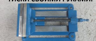
Vise
Engine mount
Engine mount (side view)
Drive belt
Making a fixture for a stationary router
You can make cutters for the machine yourself. To do this, you need to prepare a cylindrical blank. Half the diameter is cut off on it in the area where the cutting zone is formed. The transition that appears is smoothed out. Next, another quarter of the diameter is removed, and the border is smoothed. The processed area of the workpiece is given a rectangular appearance by cutting off the lower part. As a result, the thickness of the metal in the working area should be 3–5 mm. Operations are carried out using a grinder or drill with an attachment, and sharpening of the edge is carried out on a sharpening machine.
It is recommended to sharpen the cutter at an angle of 7–9 degrees. Using diamond-coated files, you can give the edge any desired shape. When making a milling cutter of complex shape, the workpiece is flattened and bent.
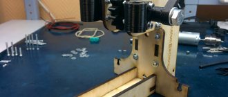
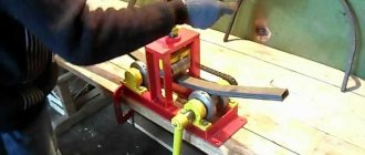
Homemade milling machine: option No. 2
A homemade machine for a drill or a hand router with self-made mechanisms for feeding the cutter and moving the work table. Below is a video of the manufacturing stages with an analysis of the key elements. Namely: rack assembly, vertical rack carriage design, machine work table drive.
Good functionality and fairly simple design
The author explains the process of making a stand for a drill, which will later become a milling machine.
Analysis of creating a cutter feed system, as well as attaching a router (or drill) to the machine stand with the ability to change tools.
Disassembly of the coordinate table drive to allow the workpiece to move relative to the cutter.
Milling cutter from a washing machine engine
Very often, craftsmen make various machines from a washing machine engine: wood lathes, drilling, sharpening, circular, as well as stationary milling machines. To make the latter, you will first need to make a table using the method described above. Next, you need to install a collet on the motor shaft to clamp the cutters.
Since it will not be possible to attach it to the motor shaft without an adapter, you will have to order one from a turner.
You will also need to make a lifting mechanism for convenient adjustment of the tool reach. It is made from two pipes that act as stands on which the engine is mounted, and a threaded rod.
One end of the pin enters the nut fixed to the bottom of the table, and the other rests against the lower part of the motor. A swivel wheel is rigidly fixed to the stud, with the help of which the height is adjusted.
To prevent dust from getting on the motor when the machine is operating, you can place a small piece of foam rubber on top of the motor.
Design and principle of operation of the equipment
If you look at the drawing of a professional milling group machine, you will notice that its design includes many different mechanisms and components. A desktop home machine, unlike a serial one, has a simpler design, consisting of a limited set of required elements. Despite the simplicity of the system, a homemade milling group machine is a fairly functional device and allows you to successfully solve many problems related to the processing of metal and wood workpieces.
One of the options for a homemade milling machine. The disadvantage is the insufficiently developed drill mount, but the design of the bed can be borrowed from here
The basis of any such machine is the bed, which must be rigid and reliable in order to be able to withstand the necessary loads. The next important element of a homemade milling group machine is the drive, the rotation from which will be transmitted to the working tool. As such a drive, you can use a hand drill or a separate electric motor with sufficiently high power.
To place and fix workpieces that will be processed on such equipment, its design must necessarily include a work table with fastening elements for the parts being processed. Processing on both professional and home milling equipment is carried out using a special tool - a milling cutter with a sharply sharpened working part.
Large machine with a powerful electric motor
When making a mini-machine for home, you should not skimp on components. They should only be of high quality, as this directly affects the reliability and performance of your equipment.
The technical characteristics that your home benchtop machine will acquire will depend on a number of parameters. These include the dimensions of the work table, as well as the permissible weight and dimensions of the workpieces that will be placed on it. An important factor influencing the performance and power of equipment is the power of the drive installed on it and the maximum number of revolutions that it can provide.
Another option for a homemade milling machine
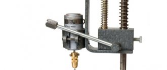
Making a router from a drill
Making a milling cutter from a drill with your own hands is easy and quick, since this tool already has a chuck into which you can clamp the cutter shank. But since the drill develops low speeds, about 3000 rpm, it will not be possible to achieve good quality machining of the part.
For comparison: a milling machine reaches speeds of up to 30,000 rpm.
A vertical drilling device, which can be purchased at a power tool store, is ideal as a stand for securing the drill. You just need to change the equipment, and the homemade router is ready.
Also, a similar stand can be made from laminated chipboard, as shown in the following figures.
Cutter with support bearing
The most elementary and compact device that sets the position of the machine is the cutter itself, if it is supplemented with a miniature ball bearing. It is located under or above the cutting knives and, accordingly, rests on the upper or lower edge of the edge. With the help of such equipment, shaped edges are obtained or grooves are cut for a connection, edging, seal, etc.
The advantages of the method include the ease of preparatory operations (you only need to adjust the vertical position) and the ability to accurately process rounded and curved edges (a typical example is a tabletop). The disadvantages follow from the advantages - it will not be possible to make a curve straight.
Selecting materials for the router
The following materials are recommended for the manufacture of a copy router:
- knee cemented polished shaft with a diameter of 16 mm;
- linear bearings – 2 pcs.;
- guide rails 90 cm long – 2 pcs.;
- rectangular pipe 30 x 60 mm and 40 x 40 mm with a wall thickness of no more than 3 mm;
- metal plate 90 x 10 cm;
- end posts – 2 pcs.;
- rocker arm for attaching the copier and cutter – 2 pcs.;
- movable coupling – 2 pcs.;
- crown type coupling for turning the part and the template.
The dimensions of all elements are specified when developing a detailed drawing.