The basic structure of a grinding machine
Without thorough knowledge of the design of grinding machines, it is impossible to assemble a high-quality device with your own hands. Before moving on to the structure, let's get acquainted with the most common types of grinders:
- Corner. Simply put, Bulgarian. Consumables are discs. Grinding wheels are designed for surface grinding. Pressure adjustment is carried out manually.
- Tape. Surface treatment is carried out with a sanding belt. Suitable for working on flat surfaces only.
- Delta sander. For processing products with a curved structure.
- Vibrating. Ideal for finishing smooth surfaces.
In addition to the above, there are several more devices that are less common:
- straight;
- polishing;
- eccentric.
Regardless of whether the device is factory-made or self-assembled, the main design elements are:
- Drive unit. The performance of the device depends on its power. Do-it-yourself devices use an electric drive, but there are pneumatic homemade ones powered by a compressor.
- Gearbox. Transmits torque from the drive to the working tool. The basic part of the gearbox is the spindle.
The gearbox is an integral part of tools such as an angle grinder or a drill. Some models, especially those assembled with your own hands, can do without it.
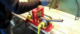
- Working platform. An abrasive material is attached to it. For this you can use circles, tapes, disks.
- Frame. Protects the structure from mechanical damage and dust, which is why many factory models are equipped with dust collection systems. The materials used to make a device with your own hands, as a rule, are not able to compete with high-quality polymers that are used in the production of professional tools.
- Control system. Includes turning off the power, as well as adjusting the abrasive speed.
Existing types of grinding machines
The industry produces several types of machines, differing both in design and purpose. Here are the main ones:
- Eccentric or orbital, in this case the base of the tool simultaneously rotates around its axis and along a certain orbit. It turns out that each time it passes in a slightly different place, so scratches and burrs are rubbed out more and more with each pass.
- Vibration model. Here the working sole carries out reciprocating movements with a frequency of about 20,000 movements per minute. It is through these movements that grinding occurs.
- An angle grinder, which is popularly called a “grinder”. Using this tool, rough processing of parts, large logs, etc. is carried out. Abrasive wheels of the required grain size are used for processing.
- Belt sander
, which is usually used for work on large surfaces. Structurally, it consists of rollers driven by an electric motor, on which sanding tape is worn.
Making a grinder from a computer hard drive + ()
Any old hard drive can be converted into a miniature grinding machine. To do this you need to follow these steps:
- completely disassemble the hard drive and remove from the case everything that is located to the left of the magnetic disks;
- cut out a working circle from sandpaper, make a hole in the center of the circle for the spindle;
- stick several strips of double-sided tape onto the rotating disk of the hard drive and secure it with sandpaper;
- make a protective screen to protect the eyes from the possible ejection of the manufactured sanding disc;
- connect the finished design to the power supply from the computer and use it.
Of course, this design does not have high power, but it is quite possible to sharpen a small knife or scissors.
Hammer drill. Features and Settings
End of article, beginning: Here
Functions of a grinding machine.
The good thing about the drill is that I changed the attachment and got a new tool. Now we will talk about using your impact drill as a powerful tool for processing various surfaces.
Rough surface treatment. To clean wooden and metal surfaces from paint, varnish, and rust, use a special drill attachment called a cup-shaped twisted cord brush. It looks like this:
When using a wire brush, follow these guidelines: — Clamp the wire brush securely in the chuck. - Work with the entire plane. — Do not press the cord brush too hard against the surface. — Do not exceed the speed indicated on the cord brush. - Hold the drill securely and firmly in your hands.
Softer surface treatment. The same treatment, but softer, is used with a different cord brush. This is what it looks like installed in your drill:
Sanding surfaces with sandpaper. If you need to sand any surface or part, for example, remove splinters from a wooden block, then by cutting out a circle of sandpaper and placing it on a special device (sanding disc), you will do this with ease. This is what the device looks like installed in a drill:
However, the matter does not end there. If you don’t have time, or you don’t want to cut out the circles from sandpaper yourself and then put them on the device, you can buy self-adhesive sanding discs for the drill. However, in this case you need to purchase another device called a “grinding support plate”. You take a plate, velcro a sanding disc to it and install it in the drill. That's it, you can start sanding:
The master's imagination is very rich. Below is an attachment called a “radial petal disk”. Each petal of such a disk is made of sandpaper. Also suitable for grinding after installation in a drill:
Polishing surfaces with a sponge. A polishing sponge is also used in conjunction with the support plate discussed above. The polishing sponge is secured to the support plate using Velcro. You install this attachment into a drill. That's it, the polishing tool is ready. You take the polishing paste, apply it to the surface to be polished, then turn on the drill and start rubbing in the polish using a sponge attached to the drill:
Knife sharpening. In stores you can also find a radial sharpening stone for a drill, which can be used, for example, for sharpening knives. This is what the whetstone looks like installed in a drill:
Screwdriver functions.
Classic screwdriver. A drill with a soft start can be successfully used as a screwdriver at low speeds. For these purposes, a special “bit holder” attachment is used on the drill. The holder is installed in the drill, and then the corresponding bit for the screw is installed in it. In this way, you can successfully quickly tighten a large number of screws, which is of course important during repairs. If your drill has a reverse, then you can unscrew these screws. If your drill has an impact impulse torque, then it can unscrew even completely ancient and long-stuck screws in the wall, which have a slot for a screwdriver ground off. Therefore, I highly recommend looking for a drill with this additional feature.
Screwdriver for hard-to-reach places. There are times when it is quite difficult to tighten or unscrew a screw (masters say “you can’t get close” to the screw).
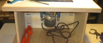
Making a grinder from a drill
To transform an ordinary, household electronic drill into a grinding machine, you need to equip it with a special attachment - a working drum or a special support plate, depending on the intended purpose.
The support is a plastic or rubber base with glued sandpaper and a shank for clamping. Discs with a flexible shaft are suitable for working with a loose drill, while those with a rigid shaft are best used only for a perfectly secured drill.
Sanding drums for a household drill are structurally an ordinary cylinder, a shank and sandpaper glued to the cylinder. Using drums, the working surface of the grinder is placed parallel to the axis of rotation.
Design of a homemade lathe from a drill
Drawings of a lathe from a drill consist of four important components: bed, headstock, tailstock, support (support).
A homemade lathe made from a drill must have a reliable, stable base, which ensures quality, accuracy and ease of processing various materials.
The most precise industrial units for metal, wood, and other materials are equipped with a massive frame on legs.
It is better for a home craftsman to make his machine more mobile. Accordingly, the frame should be light or collapsible.
With its help, the machine can be installed on a table, workbench, cabinet, moving it as needed.
The main thing is that the bed fulfills its main function, being a rigid, reliable base on which the main functional components of the machine are correctly located.
Headstock - the main task of this unit is to rigidly fix and ensure rotation of the workpiece being processed.
During operation, the part must be firmly fixed in one place and not move under the influence of vibrations.
On the other hand, the headstock can move longitudinally.
Thanks to this, it is possible to optimally arrange the working units of the device depending on the size of the workpiece being processed.
On stationary industrial machines, such a functional unit is included in the monolithic structure of the entire frame.
A homemade lathe, made from a do-it-yourself drill, uses a hammer drill or drill as this important functional part of the device, which can be easily removed if necessary. The tailstock is a movable unit of the machine that can be easily fixed in the desired place on the bed
Due to mobility, you can install workpieces of different lengths
The tailstock is a movable unit of the machine that can be easily fixed in the desired place on the bed. Due to its mobility, workpieces of different lengths can be installed.
A correctly made such device should have the most accurate adjustment of the thrust cone.
The correct pattern of the relative position of the two “headstocks” allows you to securely secure the workpieces during processing.
Caliper (hand rest) - the main task of this element of a lathe from a household drill is to act as a stop for cutting tools, which are mainly held by hand.
This device can move along the frame in the longitudinal and transverse directions and be rigidly fixed during operation.
It is important to install the support in such a position that the cutting tool arm to the workpiece is as short as possible. Video:
Video:
This will ensure safety when working with various workpieces.
It is important to consider that in a homemade lathe, the caliper has the greatest freedom of movement, moving in the longitudinal and transverse directions. This ensures an optimal working position with the desired tool lever arm.
This ensures an optimal working position with the desired tool lever arm.
The remaining two mobile units of the unit must move only along guides along the axis of the workpiece.
Manufacturing algorithm
Considering that home machines will be interchangeable in terms of the type of processing, and the decisive role will be played by the attachment installed in the drill, we will consider two main options for home-made units - horizontal and vertical.
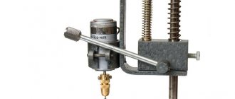
The procedure for assembling a vertical machine is as follows.
- Cut a square base 50 by 50 cm from a piece of metal or wood, with a thickness of 10 to 20 mm.
- Drill a hole in it exactly in the center at a distance of 1-2 cm from the edge for mounting the stand. The diameter of the stand must be at least 5 cm.
- Install the stand, center it using a level and weld it with a welding electrode. If you are making a wooden machine and the stand will be wooden, then firmly fix it with self-tapping screws.
- Using metal clamps, secure the drill to a movable element that will be put on the stand, forming a lowering/raising spindle.
- Place the spring on the strut. Its length must be at least 2/3 of the rack.
- Having placed the drill on the stand, mark the place where the drill will hit when lowering the spindle.
- According to this place, cut two through hollows in the frame crosswise.
- A table is installed in the groove on the threaded pin on which the workpiece will be mounted. A nut is screwed onto the pin from the bottom side; it will fix the table in the desired position. You can also attach the table to the pin from the outside with a nut, recessing it into the surface of the table so that it does not interfere with the placement of workpieces.
- It is important that after securing with a nut, the length of the outer part of the pin is flush with the top surface of the table.
The workpiece is placed on the table (fixed with clamps if necessary) and moved along the grooves in the desired direction. The drill is lowered manually and raised back up by a spring. To convert the machine into a milling or grinding machine, it is enough to replace the drill with a corresponding attachment - a milling cutter or a sanding block.
The assembly algorithm for a horizontal machine looks like this.
- Cut a rectangular frame - dimensions are determined individually.
- At one edge, secure a seat for a drill with a hollow in the upper part corresponding to the size of the tool.
- Secure the drill to it with a clamp.
- Cut a through groove for the pin along the frame, and install two metal corners along the edges along which the pressure sleeve will move.
- The width of the pressure sleeve must exactly match the distance between the guide angles (runners). A threaded pin is screwed into it from below, which will move in the hollow.
- By moving the sleeve close to the drill chuck, determine the place where the special headstock will be installed for fixing the workpieces.
- Attach the headstock to the bushing with a metal cone-shaped pin placed in the center.
- The sleeve is fixed in the desired position (for clamping the workpiece) with a nut screwed onto the pin from below.
Just like the previous one, this machine can be used not only as a lathe, but also as a milling or grinding machine. You just need to clamp the necessary working element in the drill chuck - a milling cutter, a sanding block, a drill.
In both options, it is necessary to provide special adjustable legs for the frame.
If the bed rests flat on a workbench or table, it will become impossible to adjust and fix the clamping sleeve on a horizontal machine or the workpiece table on a vertical one.
Device
The traditional version of a lathe includes the following main components: electric drive, bed (base), headstock, tailstock, caliper. An electric drill is used as an energy source (electric drive) on a homemade lathe.
bed
Designed to accommodate all other nodes. She takes all the workload on herself. Therefore, the bed must have a margin of safety. The design is minimally deformed during work, ensuring precision in the manufacture of parts.
The bed is highlighted in red
In the classic version of a lathe, the bed is a technologically difficult unit to manufacture. Its surface, mating with other assembly units included in the lathe, is made with high precision requirements. In the process of its technological processing, special high-precision equipment is used.
Headstock
In the headstock of the lathe there is an electric motor with a gearbox and a control unit. Its functions include transmission of rotation, as well as positioning of the workpiece for processing. Another name for the headstock is spindle, because the main part of this unit is the spindle. This is a multi-stage shaft with a hole inside, rotating in precision adjustable bearings.
On the side of the working area there is a flange to which a three-jaw self-centering chuck is attached. Various clamping devices, such as a collet, are installed through the holes in the shaft. Fastening the workpiece in a homemade machine is carried out using a drill chuck of an electric drill, that is, it has significant limitations.
Popular articles Poems for the holiday of April 1The control unit of a conventional lathe allows you to select almost any option for processing the part according to the technological process. In the homemade version, the function of the headstock is performed by an electric drill along with the base on which it is attached. Therefore, the choice of workpiece processing mode is limited by the functionality of the power tool.
Tailstock
To create the necessary rigidity during processing, the workpiece is fixed on both sides
This is especially important for long parts. Therefore, the back one is located opposite the front headstock.
In the tailstock body there is a thrust or rotating center that serves to press the workpiece. Cutting tools such as drills, countersinks, and reamers can be installed in the tailstock.
Caliper
The lathe support ensures that the tool is fed into the processing area. Typically, the tool is mounted in a special tool (tool holder), which is placed on the support. The kinematic design of the support allows it to move both longitudinally and transversely relative to the spindle axis. To obtain conical surfaces, the tool can be installed at an angle.
The working tools of lathes are driven both manually and with the help of mechanical devices. On homemade lathes, the tool is fed into the cutting zone mainly using manual physical force.
How to Make a Sander From a Drill
How to make a sander
When work with a wooden surface comes to an end, the final sanding step begins. To perform grinding without burrs, scratches, and to perfectly round the sharp corners of any part, you need to use a wood sander. This tool will help to perform masterful grinding even for a new person who has picked up the device for the first time. If desired, perform the grinding machine independently, using only the means at hand.
Common Mistakes
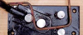
If mistakes are made during the manufacturing process of a home drilling machine, all the costs of money, time and other resources will be wasted. Typical errors are shown in the figure:
Each figure shows the following typical errors:
errors in the manufacturing process of a home drilling machine
- Low accuracy and weakness of the frame under the influence of standard load;
- The column should not be hollow inside, otherwise it will not withstand the bending load;
- The rod will not support the tool stop.
- There is no point in doubling the column transversely. This will not increase stability.
- The bump stop (in this case, the spring), due to its disproportionate size, does not dampen loads and vibrations, but rather enhances them.
- An asymmetrical arrangement of the drive and spindle on one side of the column will only increase vibrations.
- The main mistake is the lack of a bump stop as such. It must not be used as it is hazardous to health.
Many owners who independently engage in construction and construction have an electric drill. However, one such tool may not be enough for operations requiring high precision, right angle drilling or complex tasks. To achieve these goals, drilling machines are created - installations that can be made at home from scrap materials and household appliances. There is nothing complicated about how to make a drilling machine from a drill.
Additional materials (drawings):
how to make a drilling machine from a drill with your own hands drawings
how to make a drilling machine from a drill with your own hands drawings
how to make a drilling machine from a drill with your own hands drawings
Summary
Article Name Do-it-yourself drilling machine from a drill - detailed instructions, drawings
Description It is better to make or buy ➜— Do-it-yourself drilling machine ➜— Common mistakes ➜— Drawings ➜— Location of the main structural elements.
Author
Publisher Name
Wikipedia of construction tools
Publisher Logo
Do-it-yourself grinder from a drill
A belt grinding machine is used in cases where it is necessary to perform finishing processing of parts, that is, as equipment for carrying out finishing technological operations.
Most often, such machines are used in the furniture industry; they are used to process parts made from various types of wood.
But a belt grinding machine can also be used to process metal parts, for which a belt with an appropriate abrasive material is used.
Belt grinding machine
Application areas of the machine
The main tasks performed by the belt grinding machine are: final leveling of the surface being processed, bringing the level of surface roughness to the required level, bringing the processed surfaces to the level of smoothness before covering them with varnish and other finishing materials. The belt machine is also used to eliminate minor defects of the processed surface: depressions, elevations and burrs, processing the finishing coating: removing sagging primer and varnish, burr, grinding internal surfaces, processing roundings on the surface of the part.
A factory-produced option, the drawings of which can be used to create a similar homemade device.
The tape machine can be used for processing parts made of various materials: wood, plain and alloy steel, non-ferrous metals.
What’s convenient is that using a belt machine you can process parts that have different shapes: quadrangular, round and flat.
Using such equipment, it is possible to process round and tubular parts with a large cross-sectional diameter.
Design features of the machine
The working tool of any belt surface grinding machine is a belt on the surface of which abrasive powder is applied. It is made in the form of a ring and is placed between two rotating drums, one of which is the leading one and the second is the driven one.
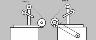
Recommendations for the direction of rotation of the machine belt
Rotation to the drive shaft of the tape machine is transmitted from an electric motor, which is connected to it via a belt drive.
The speed of movement of the belt mechanism can be adjusted, thereby changing the processing modes of parts.
The belt of a surface grinding machine can be positioned horizontally or vertically, as well as at a certain angle, which is allowed by some models of equipment in this category.
When choosing a belt sanding machine model for processing a particular part, it is important to consider the length of the surface that needs to be sanded. It is much more convenient to process parts on such machines whose surface length is shorter than the length of the abrasive belt and work table. If such conditions are met, the quality of processing will be much higher.
A homemade version of the machine is not so difficult to implement in a home workshop
The belt grinding machine can have different designs: with a movable and fixed work table, with a free belt.
A separate category includes wide-belt equipment, the peculiarity of which is that their work table, which is also a feed element, is made in the shape of a caterpillar.
In those equipment models that have a work table in their design, the abrasive belt is located in a horizontal plane, and in equipment with a free belt that does not have a work table, it can have a different spatial position.
A mandatory structural element of any belt sanding machine, including a tabletop one, is an exhaust device, which is necessary to remove dust generated in large quantities during the processing process. Both a professional and any homemade grinding machine used in a home workshop or garage are powered by an electric motor.
Principle of operation
The main operating parameters of a belt sanding machine include the feed speed and the force with which the belt is pressed against the workpiece.
Parameters such as the degree of grain size of the abrasive belt should be selected depending on the material from which the workpiece is made, as well as the degree of roughness that the surface of the machined product should have.
https://www..com/watch?v=KNo6GXiM54s
The characteristics of the material being processed, in particular its hardness, primarily influence the grit size of the abrasive belt to be selected. Processing modes that are directly related to each other are feed speed and tape clamping force.
So, if grinding is carried out at high speed, but with insignificant pressing force of the abrasive belt, then some areas of the surface of the part may turn out to be untreated.
If, on the contrary, you increase the clamping force and reduce the feed speed, you may encounter the fact that burns and blackening of the material may appear in certain areas of the surface being processed.
Another variation of the machine - view from the working surface of the belt
The results of grinding are also influenced by how well the abrasive tape is glued together.
In order to obtain high quality processing and not encounter malfunctions in the operation of the belt machine, you should not use abrasive belts that are glued incorrectly or have torn edges.
When putting the tape on the equipment shafts, it should be positioned so that the overlapping end of the seam does not ride up against the surface of the workpiece, but slides along it. Learn more about gluing tape in the video below.
Any, including a manual grinding machine, must provide the ability to adjust the belt tension, which is ensured by moving a movable shaft that is not driven. Tape tension is a very important parameter, when choosing which you should follow the “golden mean” rule.
The main characteristic for determining the degree of tension of the tape is its deflection, which is measured by lightly pressing on its surface in a tense state.
A manual belt grinding machine can be serviced by one operator, who moves the work table with the workpiece and rotates it so as to bring all areas of its surface under the abrasive belt.
How to make a belt sander
Many home craftsmen and professionals are wondering how to make a grinding machine with their own hands. The reason for this question is quite simple: the high cost of serial grinding equipment, which not everyone can pay off if not used regularly.
In order to make such equipment, you will need several main components: an electric motor, rollers and a reliable frame. Naturally, drawings of such a device or a photo of it would not be superfluous. Also at the end of the article you can watch videos on assembling a tape machine on your own.
The motor for belt grinding equipment is not difficult to find; it can be removed from an old washing machine. You will have to make the frame yourself; for this you can use a sheet of metal with dimensions 500x180x20 mm.
Such a platform must be secured to the frame very securely using several bolts.
Another version of the bed
The efficiency of a belt sanding machine directly depends on the characteristics of the electric motor that is installed on it.
If you are planning to make a grinding machine with your own hands, then an electric motor with a power of 2.5–3 kW, developing about 1500 rpm, is quite suitable for you.
In order for the sanding belt to move at a speed of 20 m/s when using such a motor, the drums must have a diameter of about 200 mm. What’s convenient is that if you choose an engine with these characteristics, you won’t need to make a gearbox for your grinding machine.
The drive shaft is connected directly to the electric motor shaft, and the second - driven - must rotate freely on an axis, which is installed in bearing units. In order for the abrasive belt to touch the surface of the workpiece more smoothly, the section of the frame on which the driven shaft is installed should be made with a slight bevel.
You can make shafts for a belt sanding machine from a chipboard with minimal financial costs.
Simply cut square blanks of 200x200 mm in size from such a plate, drill central holes in them and place them on the axle with a package with a total thickness of 240 mm.
After this, all you have to do is grind the resulting package and make it into a round shaft with a diameter of about 200 mm.
Grinding accessories
True, this is more common in a car, but you can also encounter this during ordinary apartment renovations. So, to tighten and unscrew screws in hard-to-reach places, a special drill attachment is used, which is called a “flexible shaft extension.” One end of the flexible shaft is fixed in the drill, and the other is a magnetic bit holder. You install the desired bit into the holder, and now, your tool for tightening screws in hard-to-reach places is ready:
Mixer functions.
When you really get involved in renovation work, you will be faced with the fact that you will constantly need to mix something: wallpaper glue, cement-sand mixture (CPS), floor leveler, glue for gluing tiles, plaster, putty and other. I’ll tell you right away that you can’t do this with your hands. Firstly, you will quickly get tired, and secondly, you will never be able to mix cement mortars with your hands to the state of thick, smooth sour cream! Therefore, a drill and a mixer come to the rescue. The mixer looks like this: Installed in a drill, the mixer looks like this:
How to use an impact drill
Before you start working with an impact drill, you need to set up the tool and prepare everything you need for work. Now I will talk about my drill, but for other drills the principle will be similar.
Setting the operating mode. First, understand what type of work you have to do. An impact drill has only 2 main modes - drilling mode and chiselling mode. In accordance with this, you need to set either a “drill” or a “hammer”. Let me immediately note that you set the hammer only for operating the drill in hammer drill mode. In other cases: drilling, grinding, tightening screws, mixing cement mortars is done when the switch is set to the “Drill” position.
Speed setting. For different types of work you will set different speeds. For example, if you need to drill holes in a metal plate that you want to use for a bracket, then it is better to turn on the 2nd speed. If you are going to mix cement mortar or want to tighten screws, you need to set the 1st speed. If you are going to work with a cord brush, then usually when purchasing attachments, the recommended operating speed is indicated on the packaging. Thus, you can navigate in choosing the speed. If you suddenly don’t know what speed to set for a certain type of work, consult with professionals.
Reverse setting. For all types of work, except for unscrewing screws, the direction of rotation of the drill chuck should be clockwise. To do this, the reverse switch must be set to the position where the arrow points to the cartridge.
Installation of the nozzle. Depending on the nature of the work, you install the desired attachment on the drill. I have been telling you about attachments throughout this book. So, just look at the desired section.
While working. The drill is started by smoothly pressing the start switch. (See Impact Drill Design section.) Moreover, the harder you press, the faster your drill accelerates. When pressed as hard as possible, the maximum speed will be the one you set when selecting the mode: “1st speed” or “2nd speed”. Thus, by switching the starting switch and switching speeds, you achieve a very wide speed range. If you have been drilling a surface for a long time and are tired of pressing the start switch, then for these purposes press the “Lock button” by releasing the start switch. In this option, the drill will continue to work. This is convenient because... saves your energy. You can disable this mode by pressing the start switch again.
Finally, if you are unscrewing a screw, then set the reverse switch to the position where the arrow points towards your hand. When the drill is turned on smoothly, the chuck should rotate counterclockwise.
Dangerous experiments
An impact drill will be your indispensable friend and assistant in many jobs. But there are still things that are unacceptable in operation, and I will now briefly talk about them. We will talk about a circular saw blade, which, for some reason, some people also want to install on a drill, thus building an electric saw:
Remember the rule: do not put a saw blade on a drill. Firstly, because there is no protective casing. Secondly, there will not be the necessary pressure on the material being processed. Thirdly, the drill will “walk” in your hands, and if the saw lies unevenly on the surface being sawed off, then either the disk will fly apart, or the drill will be torn out of your hands, and no one knows where it will fly! Injury guaranteed! This is very dangerous and let's not experiment like that!
How to make a belt sander
Many home craftsmen and professionals are wondering how to make a grinding machine with their own hands. The reason for this question is quite simple: the high cost of serial grinding equipment, which not everyone can pay off if not used regularly. In order to make such equipment, you will need several main components: an electric motor, rollers and a reliable frame. Naturally, drawings of such a device or a photo of it would not be superfluous. Also at the end of the article you can watch videos on assembling a tape machine on your own. The motor for belt grinding equipment is not difficult to find; it can be removed from an old washing machine. You will have to make the frame yourself; for this you can use a sheet of metal with dimensions 500x180x20 mm. One side of the frame should be cut very evenly, since it will be necessary to attach the platform on which the electric motor will be mounted to it. The platform for the electric motor should also be made of a sheet of metal with dimensions 180x160x10 mm. Such a platform must be secured to the frame very securely using several bolts.
Another version of the bed
The efficiency of a belt sanding machine directly depends on the characteristics of the electric motor that is installed on it. If you are planning to make a grinding machine with your own hands, then an electric motor with a power of 2.5–3 kW, developing about 1500 rpm, is quite suitable for you. In order for the sanding belt to move at a speed of 20 m/s when using such a motor, the drums must have a diameter of about 200 mm. What’s convenient is that if you choose an engine with these characteristics, you won’t need to make a gearbox for your grinding machine.
The drive shaft is connected directly to the electric motor shaft, and the second - driven - must rotate freely on an axis, which is installed in bearing units. In order for the abrasive belt to touch the surface of the workpiece more smoothly, the section of the frame on which the driven shaft is installed should be made with a slight bevel.
You can make shafts for a belt sanding machine from a chipboard with minimal financial costs. Simply cut square blanks of 200x200 mm in size from such a plate, drill central holes in them and place them on the axle with a package with a total thickness of 240 mm. After this, all you have to do is grind the resulting package and make it into a round shaft with a diameter of about 200 mm.
Drawings and detailed analysis of some parts of a machine made of wood.
Wood belt sander (click to enlarge)
In order for the tape to be located strictly in the middle of the shaft, the diameter of its central part should be 2–3 mm larger than at the edges. And to prevent the tape from slipping on the drum, it is necessary to wrap a layer of thin rubber on it, for which you can use an old tire from a bicycle wheel, having previously cut it along its entire length.
The sanding belt for such a machine, the optimal width of which should be 200 mm, is made from ordinary emery cloth. The standard cloth is cut into strips of the required width, and an abrasive tape is already glued from them. It should be borne in mind that the material is glued end-to-end; for this purpose, dense material is placed on the reverse side, which will strengthen the resulting seam. The properties of such a seam are greatly influenced by the glue; it must be of very high quality, then the material will not tear along the seam after a short period of use.
Several more options for manufacturing belt grinding machines can be seen in the video below.
https://youtube.com/watch?v=opM1afRob6o
Manufacturing of disc grinding machine
The disk machine is considered the easiest to manufacture. The principle of its operation resembles an ordinary electric emery. Assembly of the grinding machine is provided with step-by-step instructions.
- The working disk is cut out of plywood 1.5 cm thick. Two identical blanks are glued together. The result is a disk 3 cm thick. A hole is drilled strictly in the center, the diameter of which is equal to the thickness of the electric motor shaft.
- To assemble the frame, it is better to use an edged board, and the guides and work table are cut out of 1.5 cm thick plywood. Wood is better suited for making the machine than metal. Wood dampens engine vibrations.
- The working disc can be used for grinding and even sharpening. It is important to choose the right abrasive materials. They must be Velcro and fit for their purpose. If you need to grind a product made of stone or granite, stick a “Turtle” diamond wheel onto the working disc.
- To sand a wooden workpiece, glue a circle of sandpaper to the working disk.
- There are similar Velcro circles for metal. This disc can be used to sharpen knives, axes and other tools.
READ Which is Better: Drill Or Hammer?
When designing a disc sander, it is important to consider safety. The rotating working disk is covered with a protective arch on top. An adjustable heel is provided on the work table, which serves as a stop for the workpiece.
The table top of the machine should not be varnished or painted. Over time, an unevenly worn coating will create difficulties in moving the workpiece being processed.
Design
There is nothing particularly complicated in the design of a belt grinder. The device consists of a motor, drive and guide rollers. A sanding or roughing belt of the required grain size is passed through them.
When the engine is turned on, the drive roller mounted on its shaft begins to rotate, and through the tensioned working belt, the rotation is transmitted to the guide rollers. By pressing the part to be processed in the working area against the belt, the operator performs the required operation, changing the position of the workpiece relative to the surface of the belt if necessary.
By adjusting the distance between the guide rollers, it is possible to process surfaces with defects of different depths. During prolonged use, the sanding belt may not stretch much. To compensate for possible slack, a tension mechanism is provided in the design on one of the rollers. Typically, such a function is assigned to a roller located at the same distance between the leader and the slave.
The grinding machine is supplied with a support table, which also serves as a surface for fixing the workpiece. As a rule, such a table should be able to rotate 90 degrees about one axis. In this case, it is possible to process two perpendicularly located planes without reinstalling the part on the support table.
Of course, a grinder control panel is required! For safety reasons, it is recommended to mount it on the machine frame in close proximity to the operator’s working area. Portable machines are equipped with a stand made of durable steel with mounting holes on the base, allowing you to fix the unit on a wooden surface.
If you look at the design details, you can immediately notice some visual instability of the assembled grinding device. The overhang of the side dimensions of the installed rollers significantly exceeds the supporting surface on the base. In addition, the absence of a support table makes it difficult to effectively process relatively large surfaces, and holding the part in a canopy is inconvenient and quite dangerous.
An increased length of the working belt leads to additional losses due to friction. It is necessary to use a higher power power unit in the drive, and this increases energy costs. The tension unit is simple and functional. Adjusting the tension is a matter of seconds. The machine comes with replaceable sanding attachments, which can be used for sanding even on internal surfaces. Despite this, the cost is 100 thousand rubles. makes me think.
Lathe capabilities
Initially, I used a Soviet-made drill with thyristor speed control and a power of only 300 watts. It worked for me until the collector mechanism wore out for more than 30 years under various loads, including extreme drilling of concrete slabs. Rotary hammers were simply not on sale at that time.
This power is enough for leisurely small crafts. But for normal operation, it is better to use the design of a modern drill with at least 800 watts. The difference will immediately be felt.
For many types of work, high rotation speeds are not needed: you have to use a regulator. In this mode, the load on the engine increases, and a reserve of its power, and the entire structure, is simply necessary.
In order to increase the efficiency of the lathe, instead of a drill, I installed a three-phase asynchronous electric motor, giving it a capacitor start from a single-phase network.
This made it possible to turn long and strong workpieces like the handles of shovels and other country tools.
To attach the wooden workpiece to the engine, it was necessary to make a bushing with a locking screw on the rotation shaft and an W-shaped tip inserted into the center of the wood cut.
All the photographs show that my lathe was made a long time ago, and is stored in a workshop where humid air penetrates. Over the course of several years, clearly visible signs of corrosion appeared. Don't let this happen to your instrument.
If you are thinking about creating a lathe design for wood processing not from a drill, but from an asynchronous motor, then it is better to use a three-phase voltage of a standard value of 380 volts to power it. Power losses will be minimal.
For a single-phase 220 V network, you can connect a frequency converter, which will allow you to use all the power inherent in the design of a three-phase asynchronous motor. Such devices are available for sale at a very reasonable price. They are convenient to use on different engines.
When equipping a turner’s workplace, pay special attention to safety measures and the selection of electrical protection. Be sure to connect the electric motor only through a circuit breaker, which eliminates accidents associated with short circuits and overloads
The need to connect a power tool through an RCD is determined by local conditions. But in critical situations, protection is never superfluous.
The design of the tailstock can be improved by including a thrust bearing in the center, for example, size No. 607. The friction spent on rotating the workpiece will immediately decrease, and its combustion will be eliminated.
For a better understanding of the material, we recommend watching the video of the owner Dobry Gena “Do-it-yourself universal lathe from a wood drill.”
Useful products
- Magnetic bracelet - holder
- Souvenir coin for decision making
- Barista thermometer
Making your own grinding machine
It is impossible to make a grinding machine yourself without knowledge of the design and types of tools. The most common grinders:
- corner or otherwise Bulgarian. Discs must be replaced. The surface is polished with cleaning wheels. You can manually adjust the pressure;
- tape. For use on flat surfaces only. The work is done with a sanding belt, suitable for woodworking;
- vibration Used at the stage of finishing smooth surfaces;
- delta sander. Suitable for products with a curved shape.
Less common tools are straight sanders, polishers, random orbit sanders, and brush sanders. The device, made at the factory or with your own hands, does not differ in design. The main elements can be identified:
- Drive unit. Its power regulates the performance of the device. Mostly an electric type drive is used, but there are pneumatic devices made with your own hands. They are powered by a compressor.
- Gearbox. A machine element present on an angle grinder or drill. The basic part is the spindle. It transmits torque to the tool. There are also models that do not have a gearbox.
- Working platform. Tapes, disks or circles are used under it. Serves for fastening abrasive materials.
- Frame. The function of this element is protection from damage and dust. Factory devices have dust collection systems. When made with your own hands, the material is not able to compete with the factory analogue, since the quality of the factory model is better.
- Control system. Regulates the speed and power of the device.
Making a homemade grinder is not as difficult as it might seem. The main criterion is the correspondence between the capabilities of the device and the planned work. To save money, it is better to take the components that are on hand. There is no point in buying spare parts. Then the device will be comparable in price to the factory model. Naturally, the quality of a tool from a store is better than a home-made machine and it is more logical to take a ready-made device. Let's consider grinding machines made from scrap materials.
From the Bulgarian
The grinder is designed for grinding. We can say that it is an angle grinder, but there are some subtleties. The tool copes well with rough work, for example, removing old paint, removing corrosion or stains on metal. For factory models, there are attachments that allow for more delicate cleaning. This is possible thanks to the different grain sizes of the sanding sheet. For household appliances, operation occurs only in one mode with speeds of up to 14-15 thousand per minute.
IMPORTANT: This speed is suitable for sawing materials, but is high for sanding work.
The motor of the grinder has too much power. You need extensive experience in polishing with an angle grinder, in the presence of special polishing discs and circles. For delicate work, for example, for polishing a car, an angle grinder is not suitable. One careless movement and there will be a hole in the transport. A grinding machine needs a power of 300-400W. A do-it-yourself grinder made from an angle grinder is heavier than its factory counterpart, but you can customize your homemade grinder to suit your needs, which will make using the machine easier.
You can make an attachment for a homemade sanding machine, which will allow you to turn the device into a small belt sander. This option does not use a protective casing. If there is no possibility and desire to create nozzles, you can change the speed. Independent change will require knowledge in radio engineering. We need to create a voltage regulator. The operating procedure is as follows:
- solder using a printed circuit board;
- thyristors are adapted to radiators;
- testing is being carried out. Connect the light bulb and turn the toggle switch. The light should fade out smoothly;
- The device is mounted under the tool casing.
On expensive devices you can adjust the speed, but they cost from 10,000 rubles.
From a drill
A household electric drill equipped with a special attachment can be converted into a grinder from a drill. Depending on the task, this may be a special plate or drum. Or make a belt sander out of the tool.
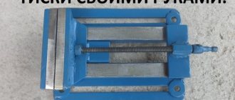
- Sanding pad. It is a plastic or rubber base with sandpaper and a tail for attaching to a drill. The flexible shaft is suitable for working with a loose drill. With hard ones, they are used with a well-fixed drill.
- Sanding drums. The drill attachment consists of a regular cylinder, sandpaper and a tail. When used, the axis of rotation is parallel to the working surface of the grinder.
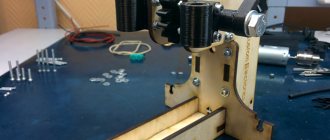
- Belt sander. The drill operates as a drive. For production you will need: rods with and without threads, profile pipe, plywood, steel sheet, bearings, various hardware and wood glue. Before manufacturing, make sure that you have a metalworking tool, a device for sawing metal. The assembly diagram is publicly available.
Orbital sander
Can only be made from a broken orbital machine. The main problem in manufacturing is the rotation of the disk. Self-production is too problematic due to the rotation device. In addition, the factory version is not too expensive, and there is no point in wasting time on this kind of machine.
Belt sander
Making this tool is not at all difficult. Follow these steps to create a belt sander:
- selection of necessary parts and materials;
- making a reliable base for mounting the tool;
- installation of countertops;
- securing the racks with the drum and tensioner;
- mounting drums and motor;
- fastening the sanding tape.
Processing large parts requires creating a large copy of the grinding machine yourself. If you install an electric motor with a power of more than 2 kW and a rotation speed of about 1500 rpm, then this is enough to rotate a drum with a diameter of 20 centimeters. This device is already used to process parts about 2 meters long.
Homemade grinder from a computer hard drive
An old hard drive can be turned into a miniature grinder. The advantage of this model is the complete absence of investment, except for the cost of abrasive wheels. Follow the easy steps to create the device:
- disassemble the hard drive and remove everything to the left of the disks;
- take sandpaper and make a circle out of it with a hole for the spindle in the center;
- secure the sandpaper by gluing it onto the rotating disk of the hard drive;
- make a screen to protect your eyes from the sanding disc flying out;
- connect to the power supply and use.
The device allows you to do small jobs. For example, you can sharpen a drill, knife or scissors. The average rotation speed is about 7600 rpm, but it all depends on the hard drive manufacturer.
Making a belt sander with your own hands + (Video)
Making a belt sander yourself is not at all difficult; you need to complete the following steps:
- select suitable materials and parts;
- create a reliable basis for securing the tool;
- install a suitable tabletop;
- secure the vertical posts with tensioner and drum;
- mount the motor and drums;
- secure with sanding tape.
To process fairly large parts and elements, it is necessary to make a large copy of a serial grinder. For example, if you take an electric motor with a power of 2 kW or more powerful with a rotor speed of 1500 rpm, then you don’t need to install a gearbox. The power of such an engine is quite enough to rotate a drum about 20 cm in diameter and process parts of about 2 m.
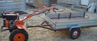
You can also use an electric motor from an old washing machine. In this case, the frame is made from a thick sheet of iron, preparing a place for installing the motor and carefully securing it with bolts to eliminate vibration. The design of such a machine consists of 2 drums, one of which is fixed, and the second can be tensioned and rotates on bearings around an axis. It is advisable to make the base for the machine from metal or several sheets of thick plywood. The drums are made on a lathe from chipboard. The tape is cut from sandpaper sheets about 20 cm wide and secured to the frame. The larger the table size, the larger the parts can be stacked and processed in the future. Drawings of finished products can be found online.
Horizontal drilling machine
This device will be useful for carpenters and furniture makers who constantly work with wood. This machine allows you to make strictly perpendicular and even holes in wooden parts in a matter of seconds, without spending a lot of effort and time.
A device that allows you to work with a drill in a horizontal position is made of the following materials:
- chipboard;
- plywood;
- tree.
First you need to drill a small hole in a piece of plywood. Next, another piece of plywood is taken, into which screws are screwed, used to drill a hole for the drill chuck.
Make sure that the hole is as precise in diameter as possible, and to do this, measure the drill chuck. After this, you can make a round blank from a piece of wood. Next, you need to glue all the parts together using PVA glue. Then clamp the parts with clamps and let them dry completely, then strengthen the fastening by screwing in several self-tapping screws. Using a round wooden piece, the exact diameter of the chuck is adjusted.
The tabletop for the machine is made of chipboard. Holes are made in it that will fix the machine in the future. Using wooden waste, you need to make stops for the drill that follow the contour, size and shape of the power tool. Please note that the drill should “lie” on its side strictly in a horizontal plane. If necessary, measure the position of the drill using a hydraulic level.
Fixation of the drill is ensured by free-running screws. The tool is ready! After completing the final calibration, you can safely use it.
Types of do-it-yourself drilling machines
There are different types of drill presses made at home. They differ in: material of manufacture, structure, size.
And home craftsmen never stop coming up with new designs and selecting sizes for drilling machines. After all, not everyone makes machines according to ready-made drawings.
Here are some of the most popular drill press designs:
Wireless machine made of wood. This design is well suited for portable drilling of large items. Since the operation of the drill in such a machine is provided by the battery, it is necessary to make a special wooden box. The machine drawing is adjusted independently to the dimensions of the built-in drill.
Mini drilling machine. Making such a tool will not take much effort and time. This design is considered the most economical and does not require a large amount of materials. The model is designed depending on the size and shape of the drill; the drill itself can be secured with ordinary rubber bands or cable ties.
Machine made of plastic pipes. This option is good for those who have pipe scraps left after plumbing repairs. In another case, this option is very economical, since PVC pipes are cheaper than metal or wood. It’s not that difficult to make, the main thing is to maintain the proportions and dimensions.
Lathe device
Regardless of the size or purpose, at their core, lathes are designed the same, they just have features that depend on the area of its application. In order to figure out how to make a lathe with your own hands, we need to take a closer look at this very device.
Many people from the school labor course can remember that the basis of everything is the bed. It is on this part that all the parts for fastening and moving the workpiece are located. It is the basis of the entire structure, and the stability and reliability of the entire machine depends on it.
For household needs, a tabletop machine will be sufficient, which does not require additional stability, making it much easier.
Next comes the headstock. Of the two main parts that are responsible for fixing the workpiece, this one is located on the side of the rotating element.
All drawings of a lathe from a drill have such a detail in their design. It is used to center the part that will be processed, and transmits the driving moment, which, in our case, will come from the drill. If the machine is a heavy model, this part will be welded to the frame, and only the height will be adjusted.
There is also a tailstock, which also acts as a fastening device. It is a moving part whose task is to secure the part and press it against the chuck, which will be mounted on the headstock. In the case of heavy machines, this part moves not only vertically, but also horizontally, thereby making it possible to process larger parts.
Last, but not least, is the caliper. It is necessary for working with the part and processing it
It does not hold it, but at the same time acts as a stop for your instrument. It is possible to work without it, but it will be terribly inconvenient, and the overall quality of the part will suffer, which is not desirable.
Woodworking Machine
The woodworking equipment market offers an extensive line of wood lathes. Each consumer makes his choice taking into account his interests, but the main criterion is the drive power. For a home workshop where turning work is performed sporadically, a simple tabletop machine with an electric motor power of 1 kilowatt and a spindle speed of 3500 rpm is suitable.
https://youtube.com/watch?v=xs8KOp1HoFI
The main components and mechanisms of a wood lathe correspond to the classic structure of a lathe, which processes workpieces by rotation. Three main mechanisms:
- drive - electric motor, single-phase or three-phase;
- transmission - a set of devices that transmit the rotation of the motor shaft to the spindle head;
- the executive is the support.
Four main nodes:
- bed - the body on which the mechanisms are fixed;
- front spindle headstock - for attaching a faceplate or lathe chuck;
- rear fixing headstock - for installing a rotating center or drill chuck.
Popular articles Decorative bottle “Memories of the Sea”
Design feature
You can assemble a wood lathe with your own hands from available materials. The design is simple and does not require much time to manufacture. The main part of the machine is a bed made of a channel, in which a groove is cut along the central center line with a grinder for fixing the tool rest and tailstock. The fixation principle is an eccentric mechanism.
The tailstock design is standard. The quill has a hole for Morse taper No. 2 to set the center of rotation. The drill chuck shank matches the quill hole. It is recommended to use a factory made tailstock.
Under the quill, machine a hollow cylinder with a blank end wall, in which a thread is cut for the flywheel screw. The moving part of the quill is a cylinder with a conical hole and a keyway along its entire length. The moving part moves with the help of a flywheel screw along a key welded in the headstock body.
The tool rest is classic, has an adjustment function with fixation to the diameter of the workpiece being processed, the base of the tool rest moves across and along the bed. It is fixed with an eccentric with a handle. The upper part is a regular corner.
The headstock has two angular contact bearings. The spindle shaft has an M14 thread, step two. This is a thread that is used on grinders and grinders. Thanks to this, all the attachments used by the grinder can be attached to the spindle.
DIY spindle head
The quality of the entire structure depends on the accuracy of the headstock manufacturing
Therefore, special attention must be paid to this node. Craftsmen recommend making the headstock of a lathe with your own hands
To do this, you need to machine a cylindrical body with a wall thickness of 10 mm. To attach it to the frame, you need to make a special stand. A section of channel is suitable for this. The channel end is welded to a corner made of sheet steel 10 mm thick. The headstock body is attached to the resulting stand.
To make a wood lathe with your own hands, drawings and dimensions do not matter, since everyone makes the design individually, taking into account their capabilities. Sectional view of a cylindrical body:
- outer diameter 56 millimeters;
- wall thickness 10 millimeters;
- length 180 millimeters;
- mounting sockets for bearings with a diameter of 24 millimeters;
- shaft with a diameter of 30 millimeters.
Simple accessories make the machine universal and increase the list of operations. For example, by installing a sanding drum with sandpaper in the chuck, you can sharpen the tool. The device for turning on a copy machine looks like this:
- copier;
- a pipe installed along the frame, acting as a slide;
- circular electric saw that acts as a wood cutter.
The milling attachment will replace the milling machine. Arbor with disc cutter
is clamped into the chuck. Instead of a tool rest, a work table with a stop ruler is installed. You can mill platbands, baseboards, and blanks for frames.
Enthusiasts and lovers of making homemade items are constantly coming up with mechanisms that make manual labor easier. Such people always have an answer to the question of how to make a woodworking machine.