Before we begin the practical connection of the starter, let us recall a useful theory: the contactor of the magnetic starter is turned on by a control pulse emanating from pressing the start button, which supplies voltage to the control coil. Keeping the contactor in the on state occurs according to the self-retaining principle - when an additional contact is connected in parallel with the start button, thereby supplying voltage to the coil, as a result of which there is no need to hold the start button pressed.
Disabling the magnetic starter in this case is possible only if the control coil circuit is broken, which makes it obvious that it is necessary to use a button with a break contact. Therefore, the starter control buttons, which are called push-button posts, have two pairs of contacts - normally open (open, normally closed, NO, NO) and normally closed (closed, normally closed, NC, NC)
This universalization of all the buttons of the push-button station was made in order to anticipate possible schemes for providing instant engine reverse. It is generally accepted to call the shutdown button the word: “ Stop ” and mark it in red. The turning button is often called the start button, start button, or is designated by the words “ Start ”, “ Forward ”, “ Back ”.
If the coil is designed to operate from 220 V, then the control circuit switches the neutral. If the operating voltage of the electromagnetic coil is 380 V, then a current flows in the control circuit, “removed” from the other supply terminal of the starter.
MP connection diagram
A popular scheme for connecting a magnetic starter via a push-button post.
The main circuit has two parts:
Our readers recommend!
To save on electricity bills, our readers recommend the Electricity Saving Box. Monthly payments will be 30-50% less than they were before using the saver. It removes the reactive component from the network, resulting in a reduction in load and, as a consequence, current consumption. Electrical appliances consume less electricity and costs are reduced.
- Three pairs of power contacts direct electrical power to electrical equipment.
- A graphical representation of the control, which consists of a coil, buttons and additional contactors that take part in the operation of the coil or prevent erroneous activation.
The most common wiring diagram is with one device. It's the easiest thing to deal with. To connect its main parts, you need to take a three-core cable and a pair of open contactors when the device is turned off.
Scheme with connecting a 220 volt coil
Will analyze a design with a voltage of 220 volts. If the voltage is 380 volts, you need to connect a different type of phase instead of the blue zero. In this situation, black or red. In case of blocking of the contactor, the fourth pair is taken, which works with 3 power pairs. They are located at the top, but the side ones are located on the side.
Pairs of power contactors are supplied with 3 phases A, B and C from the machine. To turn on when you touch the “Start” button, it is necessary that the voltage be equal to 220 V on the core, which will help the movable contactors connect with those that are stationary. The circuit will begin to close; to disconnect it, you need to disconnect the coil.
To assemble the control circuit, you need to connect one phase directly to the core, and connect the second phase using a wire to the start contact.
From the 2nd contactor we lay 1 more wire through the contacts to the other open contact of the “Start” button. A blue jumper is also made from it for the closed contactor of the “Stop” button; a zero from the electrical supply is connected to the 2nd contactor.
Working principle
The operating principle is simple. If you press the “Start” button, its contacts begin to close and a voltage of 220 volts flows to the core - it triggers the main and side contacts and an electromagnetic flux occurs. If the button is released, the contactors of the start button open, but the device is still turned on, since zero is transmitted to the coil through the closed blocking contacts.
In order to turn off the MP, you need to break the zero by opening the contacts of the “Stop” button. Again the device will not turn on, because the zero will be broken. To turn it on again, you will need to click “Start”.
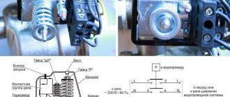
How to connect a thermal relay?
You can also make a single-line graphic drawing of the connection of a three-phase electric motor to a magnetic starter via a relay.
Between the MP and an asynchronous electric motor, a relay is connected in series, which is selected depending on the specific type of motor. This device protects the motor from breakdowns and emergency conditions (for example, when one of the three phases disappears).
The relay is connected to the output from the MP to the electric motor, electricity passes through it in a series manner through the heating of the relay to the electric motor. On top of the relay there are additional contactors, which are combined with the coil.
Relay operation
Thermal relay heaters are designed for the maximum current that passes through them. When the current rises to unsafe limits for the motor, the heaters turn off the MP.
Installation of starters inside an electrical panel
The design of the MP allows installation in the middle of the electrical panel. But there are rules that apply to all devices. To ensure high reliability of operation, it is necessary that the installation be made on an almost straight and solid plane. Moreover, it is located vertically on the wall of the electrical panel. If there is a thermal relay in the design, then it is necessary that the temperature difference between the MP and the electric motor be as small as possible.
Installation Tips and Tricks
- Before assembling the circuit, you need to free the working area from the current and check that there is no voltage with a tester.
- Set the core voltage designation which is mentioned on it and not on the starter. It can be 220 or 380 volts. If it is 220 V, phase and zero go to the coil. Voltage marked 380 means different phases. This is an important aspect, because if connected incorrectly, the core may burn out or will not fully start the necessary contactors.
- Starter button (red) You need to take one red “Stop” button with closed contacts and one black or green button with the inscription “Start” with invariably open contacts.
- Please note that power contactors only force or stop the phases, and the zeros that come and go, conductors with grounding are always combined at the terminal block, bypassing the starter. To connect a 220 Volt core to the addition, 0 is taken from the terminal block into the design of the starter organization.
You will also need a useful device - an electrician's tester, which you can easily make yourself.
{SOURCE}
The difference between a magnetic starter and a contactor
Often, when selecting a switching device, confusion arises between magnetic starters (MF) and contactors. These devices, despite their similarity in many characteristics, are still different concepts. A magnetic starter combines a number of devices; they are connected in one control unit.
The MP may include several contactors, plus protective devices, special attachments, and control elements. All this is enclosed in a housing that has some degree of moisture and dust protection. These devices are mainly used to control the operation of asynchronous motors.
The maximum voltage with which the magnetic starter operates depends on the electromagnetic inductor. There are MFs of small ratings - 12, 24, 110 V, but most often they are used at 220 and 380 V
A contactor is a monoblock device with a set of functions provided for by a specific design. While starters are used in quite complex circuits, contactors are mainly found in simple circuits.
⑤ Car engine start button, ignition start switch
Rating: 4.7 Price: 256.03 rub.
Go to store Compact and programmable start-stop device with LED lighting is used to quickly start the engine. It is made of waterproof stainless steel, so it works even in wet conditions. Installing the button does not require the help of a specialist - just insert the housing into the connector on the front panel of the car. There are 2 colors available to choose from – silver and black.
Advantages:
- has a backlight;
- made of metal;
- waterproof.
Flaws:
- non-latching button - closed while pressed.
Buy on AliExpress.com
Design features
Depending on the number of controlled electricity consumers, the posts can be two-button ("Start" and "Stop" pushers) and multi-button. In addition, when performing electrical and electrical work, single buttons are used, which the user can independently install on any control panel.
Push-button stations are mounted in a plastic or metal case that has mounting holes for installing the fittings in a place convenient for use. A separate group consists of push-button stations designed to control hoists (PKT series), beam cranes and overhead cranes with ground control.
The main functional element of the device that starts, stops or switches the modes of the electricity consumer is a push button - an electrical switching fixture with manual control.
Today, control panels use two types of pushers:
- With self-return, in which the button returns to its original state due to a return spring installed on the pusher on the bottom side.
- Pushers with position fixation (self-holding), which close the contact and hold it until pressed again.
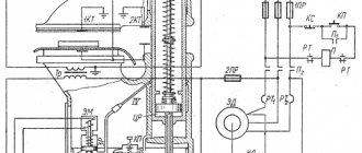
The most common is a two-button starting valve, the design of which is shown in Fig. 2. The remote control consists of a housing 1 and a front panel 2, which are connected to each other by screws 3. The buttons are painted in different colors and control a pair of contacts located inside the housing.
In the free state of the “Start” button, its pair of contacts is open, while the “Stop” button, on the contrary, is closed. When you press the start button, its contacts close.
There are a huge number of switching schemes for various electrical systems and devices with just two buttons. However, most of them do not provide direct voltage supply to the consumer, but through the contacts of a magnetic starter, which are designed for high currents and voltages.
The pushers themselves have different shapes and colors, which in fittings produced in Russia are usually reflected in their symbol.
According to their shape, pushers are divided into:
By pusher color:
- Stop buttons are usually colored red (“R”) or yellow (“G”);
- “Start” pushers can be black (“B”), blue (“C”), green (“Z”) or white (“B”).
③ Car engine Start Stop button
Rating: 4.8 Price: RUB 330.16
Go to the store A luminous red button with a removable chrome surround is installed in the car's dashboard, next to the gearbox. The kit only comes with a start-stop device, no instructions. Due to its small size, it requires minimal power consumption.
This model has bright backlighting. The built-in high-quality module ensures uninterrupted operation of the button in any climatic conditions and temperature range from -50 to +5 degrees. It is recommended to check the size chart before purchasing.
Advantages:
- presence of backlight;
- work in any weather conditions
Flaws:
- marking.
Buy on AliExpress.com
The principle of operation of a magnetic starter and a small-sized contactor + Video explanation
Sometimes the question arises: why use MP or KM at all, why not just use a three-pole machine?
- The machine is designed for up to 10 thousand shutdowns and starts, and for MP and KM this figure is measured in millions
- During power surges, the MP (KM) will turn off the line, playing the role of protection
- The machine cannot be controlled by remotely applying a small voltage
- The machine will not be able to perform additional functions of turning on and off additional circuits (for example, signal circuits) due to the lack of additional contacts
In a word, the machine perfectly copes with its main function of protection against short circuits and overvoltages, and MP and PM do theirs.
That's all, I think that the principle of operation of MP and CM is clear, for a more clear explanation, see the video.
Happy and safe installation!
In addition to the article, I attach technical documentation for KMI series contactors
Cost indicators
The cost of Russian push-button posts is quite low and depends primarily on the number of buttons, category of placement and climatic design. Devices in a metal case are slightly more expensive than analogues installed in a plastic case.
For example, the price of two-button devices “PKE-222-2” is in the range of 250.0...280.0 rubles. A similar device with a mushroom-shaped “Stop” button will cost a little more – 380.0 rubles.
The price of one-button posts does not exceed 150 rubles. The six-button telpher remote control “PKT-60” costs 300.0 rubles. A device with a similar number of buttons and electrical parameters, equipped with a key (“foolproof”), will cost 200.0 rubles more.
② LEEPEE 12V engine start and stop button
Rating: 4.3 Price: RUB 384.43
Go to the store The Chinese engine start-stop button LEEPEE 12 is highlighted with bright backlighting, which allows the driver to start the car at night without any problems. Installation does not require any help - just connect three wires under the steering panel.
The model supports touch pressing. External diameter – 41 mm. The device also has protection against accidental pressing. To start the machine, you need to press the touchpad. To plug it, you will have to completely stop the car and then press the brake pedal. Only after this the button will work.
Advantages:
- presence of backlight;
- nice design.
Flaws:
- not detected.
Button
Buy on AliExpress.com
Start button.
As a result, the contacts are closed. There are two types of MF with contacts: Normally closed - power supply to the load is turned off at the moment the starter is triggered. For example, if the electric motor is 1.5 kW.
While some machine, such as a sawing machine, was operating, the voltage in the network was lost. What series of starter are you demonstrating in the video??? The reversing starter must have mechanical protection against simultaneous activation of its two halves.
They are located at the top of the starter housing. Power is supplied to the device through contacts located on the top of the MP housing.
They have 2 pairs of contacts. It is often used in practice, noting its high reliability. When controlling the machine's electric motor using a magnetic starter, the machine will not turn on until the "Start" button is pressed. Start stop, connecting a magnetic starter
Design and principle of operation
A good example. One of the new applications is implementation in lighting and alarm control systems. One receives power, the other leaves it. Depending on how the coil is wound, the rating of the contactor changes. The design may also include, as additional elements, a protective relay, electrical fuses, an additional set of terminals, and a starting device.
So what's the difference?
This creates an electrical interlock that prevents two contactors from being supplied with power at the same time.
When voltage appears, the start button is pressed, for example, the coil generates an electromagnetic field that attracts the upper part of the core.
In practice, often, the main application of contactors and magnetic starters is the starting and stopping of asynchronous electric motors, their control and reversal of engine speed. On the upper part of the magnetic circuit there are two groups of contacts - movable and fixed. The contacts close, power is supplied to the load, and as a result, it starts working. Connecting an electromagnetic starter part No. 3
See also: Connection diagram for 2-key switch
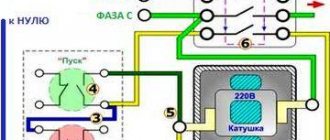
220 volt coil: connection diagrams
To control the operation of the magnetic starter, only two buttons are used - the “Start” button and the “Stop” button. Their design can be different: in a single housing or in separate housings.
Buttons can be in the same housing or in different ones
Buttons produced in separate housings have only 2 contacts, and buttons produced in one housing have 2 pairs of contacts. In addition to the contacts, there may be a terminal for connecting the ground, although modern buttons are produced in protected cases that do not conduct electric current. Push-button stations in a metal case for industrial needs are also produced, which are highly impact resistant. As a rule, they are grounded.
Connection to 220 V network
Connecting a magnetic starter to a 220 V network is the simplest, so it makes sense to start familiarizing yourself with these circuits, of which there may be several.
A voltage of 220 V is supplied directly to the coil of the magnetic starter, which are designated as A1 and A2, which are located in the upper part of the housing, as can be seen from the photo.
Connecting a contactor with a 220 V coil
When a regular 220 V plug with a wire is connected to these contacts, the device will start working after the plug is plugged into a 220 V socket.
Using power contacts, it is permissible to turn on/off an electrical circuit for any voltage, as long as it does not exceed the permissible parameters indicated in the product passport. For example, you can apply battery voltage (12 V) to the contacts, with which a load with an operating voltage of 12 V will be controlled.
It should be noted that it does not matter which contacts the single-phase control voltage is supplied to, in the form of “zero” and “phase”. In this case, the wires from contacts A1 and A2 can be swapped, which will not affect the operation of the entire device. It is quite natural that such a connection circuit is used extremely rarely, since it requires direct voltage supply to the coil of the magnetic starter
In this case, there are many options for switching on, using a time relay or a twilight sensor, connecting, for example, street lighting to power contacts. The main thing is that the “phase” and “zero” are nearby
It is quite natural that such a switching circuit is used extremely rarely, since it requires direct voltage supply to the coil of the magnetic starter. In this case, there are many options for switching on, using a time relay or a twilight sensor, connecting, for example, street lighting to power contacts. The main thing is that the “phase” and “zero” are nearby.
Using the Start and Stop buttons
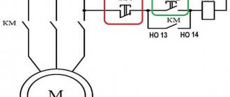
Basically, magnetic starters are involved in the operation of electric motors. Without the presence of the “Start” and “Stop” buttons, such work is associated with a number of difficulties. This is primarily due to the operating characteristics of electric motors, which are often located at a considerable distance. The buttons are connected to the coil circuit in series, as in the figure below.
Switching diagram of a magnetic starter with buttons
This method is characterized by the fact that the magnetic starter will be in working condition as long as the “Start” button is pressed, which is very inconvenient. In this regard, the circuit includes additional (BC) contacts of the magnetic starter, which duplicate the operation of the “Start” button. When the magnetic starter is turned on, they close, so after releasing the “Start” button, the circuit remains operational. They are designated in the diagram as NO (13) and NO (14).
Connection diagram for a magnetic starter with a 220 V coil and a self-retaining circuit
You can turn off running equipment only using the “Stop” button, which breaks the electrical power supply circuit of the magnetic starter and the entire circuit. If the circuit provides other protection, for example, thermal, then if it is triggered, the circuit will also be inoperable.
Power for the motor is taken from the T contacts, and power is supplied to the magnetic starter contacts, designated L.
This video explains in detail and shows in what order all the wires are connected. In this example, a button (button post) is used, made in one housing. As a load, you can connect a measuring device, an ordinary incandescent lamp, a household appliance, etc., operating from a 220 V network.
How to connect a magnetic starter. Connection diagram.
Watch this video on YouTube
How to change the direction of rotation of a motor using a starter
Three-phase electric motors make it possible to set the direction of rotation. There are many schemes for single-phase 220 V power supply. And for three-phase (380 V) switching, there is a connection diagram for a reversible magnetic starter.
The device consists of two independent circuits, with separate control of each group of contacts (pm1 and pm2). Each solenoid winding (PM1 and PM2) is controlled by its own button. In this case, there is only one stop key; it simply breaks the control circuit (as in a single starter). The connection of the input and output contacts of the second group is made with the so-called “phase shift”. In this case, the windings of the electric motor create torque on the shaft in the opposite direction.
The thermal relay is unchanged: their task is to open the starter in case of overload.
There is one feature:
To prevent a short circuit between phases, groups of contacts (pm1 and pm2) should not be closed at the same time. Therefore, they are mechanically placed on one rod, and purely physically cannot be connected to the power bus together. If you try to press the second button (while the first one is working), the power supply to the consumer will turn off.
Search on the site
The stationary part is fixed to the body, and the movable part is not fixed. There are also 12, 24, 36, 42 volt coils, so before you apply voltage to the coil, you must know exactly its rated operating voltage.
The easiest way is to consider them separately to make it easier to understand the principle of organizing the circuit. This means that the three-pole circuit breaker must be set to 3 or 4A.
Certain minor adjustments will be made for the power circuit. If there are special safety requirements and high humidity in the room, it is possible to use a starter with a 24-12 volt coil. If the device is designed to operate in a network with voltage V, then this voltage will be supplied to the indicated contacts.
You are right. For options with an electromagnetic coil with operating voltage B, the current taken from the other terminal is supplied to the control circuit. Who will hold the well with his hand all the time? When a wire with a plug is connected to them, the device is connected to the network.
We recommend: Laying cables underground norms
Supports operation in a network with alternating or direct voltage. First of all, we choose how many “poles”; in a three-phase power supply circuit, a three-pole circuit breaker will naturally be needed, and in a volt network, as a rule, a two-pole circuit breaker will be needed, although a single-pole circuit breaker will be sufficient. What series of starter are you demonstrating in the video??? As a result, the contacts are closed.
If you transfer the phases on the corresponding contacts, you can easily achieve this effect from any motor device. For example, the PKI prefix.
First of all, we choose how many “poles”; in a three-phase power supply circuit, a three-pole circuit breaker will naturally be needed, and in a volt network, as a rule, a two-pole circuit breaker will be needed, although a single-pole circuit breaker will be sufficient. For example, for a 4kW motor, you can install a 10A automatic.
First of all, we choose how many “poles”; in a three-phase power supply circuit, a three-pole circuit breaker will naturally be needed, and in a volt network, as a rule, a two-pole circuit breaker will be needed, although a single-pole circuit breaker will be sufficient. A rigid spring is installed inside the coil on the central core, which prevents the contacts from connecting when the device is off. Reversible connection diagram for a magnetic starter
How to install a button yourself instead of the ignition switch with aliexpress
If you nevertheless set out to equip your iron horse with such a device, it’s time to get acquainted with the features of its installation. At the moment, there are several ways to install the start-stop button. Let's consider the most common and fairly simple method.
To bring this idea to life, we will need a minimum set of components from Aliexpress, which includes:
- four-pin relays;
- connecting wires;
- diode;
- the actual start-stop button.
Once all the components have been found, it’s time to start installing the system itself.
At this stage, it is important to adhere to a certain sequence of actions. This approach will save you from all sorts of unwanted surprises, which in the future can result in serious problems
The installation algorithm involves the following steps:
- the positive terminal of the battery should be connected to the positive contact of the relay;
- the enabling “+” relay is also connected to the battery;
- the negative terminal is mounted to the ground of the car;
- the control contacts of the load relay are connected to 12V;
- the control negative output is connected to the corresponding output of the button;
- the enabling positive signal remains unconnected.
The presented installation diagram differs from all others in its ease of implementation and should not cause difficulties even for a novice car enthusiast.
What is included in the package, tools and consumables
It would not be superfluous to mention the completeness of the device in question. Due to the fact that currently there is an abundance of all kinds of analogues and modifications
given device, it is important to choose the most suitable one
It often happens that, due to his lack of awareness, a car enthusiast, ordering a “start-stop” button on various trading platforms, falls for the tricks of scammers or simply unscrupulous sellers
That is why it is important to know which consumables should be included with this device.
So, the complete set of delivery assumes the presence of:
- the “start-stop” button itself;
- control module;
- connecting wires with connectors.
However, the standard package does not allow you to assemble a working circuit for this device. To do this you will need to buy several more relays.
Connection diagram
To connect the device to the car, you must follow a specific connection diagram. We bring to your attention one of these schemes with a detailed explanation of the operation of key elements.
Here's another diagram, maybe it will be easier to navigate.
How to connect the device correctly
When installing a button, it is extremely important to avoid making mistakes when connecting one or another node. To do this, you must be guided by the above diagram
It is also worth noting that one diagram will not be enough to carry out the button installation procedure. In this case we are talking about various kinds of accompanying actions. Let's look at them in more detail.
Before implementing the planned project, you will have to perform some actions, namely:
- remove the ignition switch;
- remove the steering wheel lock mechanism;
- disconnect the underwater leads;
- remove the immobilizer antenna;
- install the button in the most suitable place for yourself;
- connect underwater wires.
After carrying out the above actions, the stage of checking the system for operability follows. If you follow the instructions supplied with the device, such a procedure should not cause serious difficulties.
Video on connecting the Start-Stop button
To get acquainted with the installation of the presented device, we invite you to watch a video dedicated to the topic in question.
In it you will find useful information that will help save you from all sorts of troubles at all stages of system assembly.
Problems with keyless car starting system
As noted earlier, the use of such a system is associated with a number of problems. Most of them cause inconvenience only in the absence of certain skills in using the presented system.
This may include:
- the need to manipulate the brake pedal;
- inconsistent operation of the system in the presence of the “autostart” function.
How to unlock the steering wheel
Another important problem that motorists who have equipped their cars with such a system often face is unlocking the steering wheel. Of course, as a last resort, you can resort to a barbaric method and get rid of the blockage using simple manipulations with a mounting tool and other tools.
On the subject: How to check the electronic gas pedal and repair it if necessary
You can solve this problem as follows:
- The first option involves making a duplicate of the ignition key, sawing off the top part, inserting the piece into the lock and turning the key to position 2, which means the steering wheel is unlocked.
- The second method involves completely dismantling the ignition switch; by the way, the start-stop button itself can be mounted in the resulting hole.
But it’s still much easier to use the services of professionals. The fact is that it is not always possible to unlock the steering wheel yourself, due to the characteristics of a particular car. Therefore, in this case, it is best to contact specialists.
220 volt coil: connection diagrams
To control the operation of the magnetic starter, only two buttons are used - the “Start” button and the “Stop” button. Their design can be different: in a single housing or in separate housings.
Buttons can be in the same housing or in different ones
Buttons produced in separate housings have only 2 contacts, and buttons produced in one housing have 2 pairs of contacts. In addition to the contacts, there may be a terminal for connecting the ground, although modern buttons are produced in protected cases that do not conduct electric current. Push-button stations in a metal case for industrial needs are also produced, which are highly impact resistant. As a rule, they are grounded.
Connection to 220 V network
Connecting a magnetic starter to a 220 V network is the simplest, so it makes sense to start familiarizing yourself with these circuits, of which there may be several.
A voltage of 220 V is supplied directly to the coil of the magnetic starter, which are designated as A1 and A2, which are located in the upper part of the housing, as can be seen from the photo.
Connecting a contactor with a 220 V coil
When a regular 220 V plug with a wire is connected to these contacts, the device will start working after the plug is plugged into a 220 V socket.
Using power contacts, it is permissible to turn on/off an electrical circuit for any voltage, as long as it does not exceed the permissible parameters indicated in the product passport. For example, you can apply battery voltage (12 V) to the contacts, with which a load with an operating voltage of 12 V will be controlled.
It should be noted that it does not matter which contacts the single-phase control voltage is supplied to, in the form of “zero” and “phase”. In this case, the wires from contacts A1 and A2 can be swapped, which will not affect the operation of the entire device.
It is quite natural that such a switching circuit is used extremely rarely, since it requires direct voltage supply to the coil of the magnetic starter. In this case, there are many options for switching on, using a time relay or a twilight sensor, connecting, for example, street lighting to power contacts. The main thing is that the “phase” and “zero” are nearby.
Starter connection diagram
Switches are used to supply power to various electrical appliances. Depending on the power of the electrical installation, the contacts of the switches are designed: the higher the current (power consumption), the greater the mass and contact area of the metal. Accordingly, the clamping device (spring, steel plate) must provide greater pressing force. If the switch is manual (mechanical), its size will be too large and it will be inconvenient to use.
Such input devices have a number of disadvantages (in addition to dimensions):
- too much effort when turning on (off);
- contact groups are not designed for frequent switching: they wear out quickly;
- safety issues have not been resolved: too much time is wasted when emergency shutdown is necessary;
- “switches” must be placed near the work area (in close proximity to the electrical installation), this is not always convenient due to the same dimensions.
The only way out is to connect the motor (or other electrical appliance) through the starter.
Advantages of implementing such a connection scheme
- The switch and control manipulator (button) can be separated. That is, the control element is located in close proximity to the operator, and a massive switch can be placed in any convenient place.
- It is possible to control it using a foot drive (hands remain free). This allows you to better control the electrical installation and hold the workpiece.
- The remote starter connection diagram allows you to place safety devices. For example, protection against short circuits or thermal relays that are triggered by temperature overloads. In addition, this circuit allows for mechanical protection: when the moving parts of the electrical installation move to a critical point, the limit switch is triggered and the magnetic starter opens.
- The remote location of the control elements allows the emergency button to be located in a convenient location, which increases operational safety.
- It is possible to install a single push-button station to control a large number of magnetic starters when electrical installations are located in different places and at great distances. The connection diagram through such a post involves the use of low-current control wiring, which saves money on the purchase of expensive power cables.
- To control one starter, you can install several push-button stations. In this case, control of the electrical installation from each post will be equivalent. That is, you can start the electric motor from one point and turn it off from another. Connection diagram for several push-button posts in the illustration:
- Magnetic contactors can be integrated into an electronic control system. In this case, commands to start and shut down electrical installations are sent automatically, according to a given algorithm. It is impossible to organize such a system using mechanical (manual) switches.
In fact, such switching is a relay circuit.