The very idea of using a rectifier to charge car batteries is not new. But not everyone is ready to undertake such experiments. The reason is more than banal. Rather than building some kind of structure from improvised means, it is easier to purchase a ready-made, certified charger.
Many people are interested in whether it is even possible to use a rectifier to charge a car battery. Of course you can. This can be done for both standard 12 V and 24 V batteries. But since 12-volt starter batteries are the most in demand and popular, the main emphasis will be on them.
The nuances of battery operation
The most common type is the lead-acid battery. The service life of the device is calculated on average for 5 years. Recharging such batteries requires using at least 10% of the current from the total capacity of the device.
For example, with an indicator of 75Ahh, a minimum current value of 7.5A is required for charging. If the current is higher, the battery will not fail, but the car may lose its brains.
Repairing the control unit for air conditioning, gearbox, alarm system, and so on is not a cheap pleasure.
A device with a voltage of 11.9-12.1 Volts is discharged; in working condition, the charge level should be 12.5-12.7 Volts.
Microwave oven charger
Some car enthusiasts use a transformer from a broken microwave oven. But this transformer will need to be redone, since it is a step-up transformer, not a step-down transformer.
It is not necessary that the transformer be in good working order, since the secondary winding in it often burns out, which will still have to be removed during the creation of the device.
Remaking the transformer comes down to completely removing the secondary winding and winding a new one.
An insulated wire with a cross-section of at least 2.0 mm is used as a new winding. sq.
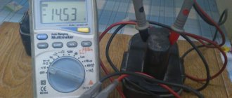
When winding, you need to decide on the number of turns. You can do this experimentally - wind 10 turns of a new wire around the core, then connect a voltmeter to its ends and power the transformer.
According to the voltmeter readings, it is determined what output voltage these 10 turns provide.
For example, measurements showed that there is 2.0 V at the output. This means that 12V at the output will provide 60 turns, and 13V will provide 65 turns. As you understand, 5 turns adds 1 volt.
Scheme.
Well, then everything is done as described above - the diode bridge is made, all the components are connected and the functionality is checked.
It is worth pointing out that it is better to assemble such a charger with high quality, then place all the components in a case that can be made from scrap materials. Or mount it on a base.
Be sure to mark where the “positive” wire is and where the “negative” wire is, so as not to “over-plus” and damage the device.
Conditions for homemade battery charging
To charge the device, the following requirements must be met:
- Constant voltage setting – 14.4V;
- Possibility of charging for a long time;
- Automatic shutdown when maximum current values are exceeded;
- Protection against pole connection error. When connecting minus to plus, the charging process must be stopped.
Any violation of the above requirements may irreversibly damage your device.
No need!
Let's first talk about typical mistakes in designing homemade chargers for lead batteries. The first is illustrated by pos. up. Connecting directly to the household electrical network (left) is not worth discussing. This is not a mistake, this is a gross and dangerous violation of safety regulations. The error is in limiting the charging current by capacitive ballast. Expensive, by the way, this is a method by today's standards: the battery of oil-paper capacitors alone at 32 uF 350 V (lower voltage is not possible) costs more than a good branded charger.
Incorrectly and irrationally constructed charger circuits for car batteries
But the main thing is that a reactive load appears in the network. If your electric meter has a reactivity indicator (LED “Return”), then when these charges are plugged into the network it will flash. Managing modern electrical equipment is impossible without computers, and the “return” confuses the electronics even to the point of shutting down due to a false alarm. That's why today's electricians are merciless when it comes to reactive power. Well, what if it turns out that its source is illiterate or an overly cunning consumer, then... let’s not look into the night.
The circuit below, if we take into account the same capacitive ballast, was developed skillfully, this charger will protect the battery, figuratively speaking, from the Tunguska meteorite; (a detailed description of it can be found here: https://ydoma.info/avtomobil-zaryadnoe-ustrojstvo-dlya-avtomobilnogo-akkumulyatora.html). But, with all due respect to the author, who certainly knows his business, building such a difficult (and expensive) charger for lead batteries is like assigning a nanny from a kindergarten to command a platoon of experienced, seasoned soldiers. A lead battery needs little to live well. What will we do next?
Models of homemade battery chargers
Any homemade charger does not provide any guarantee of long-term operation. The main thing here is simplicity and efficiency. Next, let's look at examples of how you can charge a car battery yourself.
Battery charging requirements
Before carrying out the procedure for making a homemade battery charger, you must pay attention to the following requirements:
- Providing a stable voltage of 14.4 V.
- Device autonomy. This means that a homemade device should not require supervision, since the battery is often charged at night.
- Ensuring that the charger turns off when the charging current or voltage increases.
- Reverse polarity protection. If the device is connected to the battery incorrectly, the protection should be triggered. For implementation, a fuse is included in the circuit.
Polarity reversal is a dangerous process, as a result of which the battery may explode or boil. If the battery is in good condition and only slightly discharged, then if the charger is connected incorrectly, the charging current will increase above the rated one. If the battery is discharged, then when the polarity is reversed, an increase in voltage above the set value is observed and, as a result, the electrolyte boils.
Using a lamp and a semiconductor diode
This method of recharging a battery device is relevant at home. To implement this, you must have a 220V outlet.
- The circuit elements include a standard 100-150 Watt incandescent lamp, a semiconductor diode, a socket plug and a cable with crocodile clips.
- In this connection, the diode serves as a voltage converter from AC to DC.
- To prevent a short circuit, it is enough to use a 10-15 A fuse. The lamp and diode must be connected to the “+” of the battery.
With a lamp power of 100 watts, the incoming current will be 0.17A. To achieve a value of 2A, you will need to charge the battery for at least 10 hours.
Most likely, it will not be possible to completely restore the charge of a dead battery, but it will be enough to start the car.
How the memory works and works
The principle of operation of the charger, which is based on the rectifier of the sample in question, is quite simple. Actually, this is the goal being pursued. It needs to be connected to the battery and put into operation.
A novice designer will need to do the following:
- press the start button to supply voltage to the transformer;
- this will activate the Pk relay;
- the relay will connect contacts that are connected in parallel to the start button;
- the circuit will be fixed and will conduct current as long as there is voltage on the coil;
- the relay works as protection against accidental short circuits and rectifier overload;
- in the event of a short circuit or high current, the voltage drops and the relay immediately opens;
- thereby turning off the power supply to the transformer, preventing damage to the rectifier;
- the design also includes a voltage switch with LEDs;
- this element indicates the current output voltage;
- it is potentially possible to connect two windings in parallel to make the output current larger;
- to obtain other voltage parameters, you can solder other LEDs and relays into the circuit;
- To make the front panel, just print it out on a printer using adhesive paper.
It is also recommended to add a fuse to the circuit at the rectifier output. This will create an additional level of protection for the battery if a bridge breakdown occurs. Also, the mains fuse will not interfere with the winding. In the case of such a circuit, the rectifier will have output voltage parameters of 14 and 28 V, and the current for charging the battery will be about 3.5 A.
Many people are concerned about the fact that there is no current regulator here. In principle, there is no special need for this element here. For the existing efficiency, this is an extra component. The maximum current of 3.5 A is enough to easily charge batteries with a capacity of 35 Ah and above.
At the same time, there is definitely no threat of overload. Features if the nominal capacity of the serviced battery is 40-45 Ah or more. After all, here the voltage parameters will be small, and the current drop will occur as the voltage increases.
Of course, before you charge your battery with such a homemade rectifier, do not forget about the need for correct connection, compliance with polarity, as well as the need for constant monitoring of the process. However, the design does not provide for an automatic switch.
Ideally, chargers operate with a charging current that can be adjusted depending on the battery capacity, setting the value to 10% of the nominal parameter. And the charging voltage should not go beyond 13.8 V in normal charging mode, or beyond 15 V during the accelerated capacity restoration procedure.
A circuit breaker and protection elements against short circuits and overloads must also be provided. But all these are chargers of a completely different, high level. And those who understand little in this area should not get involved with the assembly of such systems. You can get by with a regular rectifier and the simplest circuit shown above.
When the transformer is supplied with a voltage of 20 V, the charging current will be higher than 10 A. And if it is 10 V, then most likely no current will flow at all.
In the case of battery recharging, in most cases 5 A is more than enough. Remember one more important thing. The greater the charge current from the charger, the faster the battery will ultimately fail and require replacement.
Charging model assembled from a PC power supply
The standard power supply for a personal computer is rated at 12 Volts. To charge the battery, we remind you that you will need at least 14.4 Volts.
First, all unnecessary wires are unsoldered; for charging you will only need green wires. The end of this cable is soldered to the negative contacts where the black wires exit.
- This circuit allows you to start the charger directly. The wires coming from the battery terminals are connected to the minus and plus on the power supply. The plus is soldered where the yellow cable exits, and the minus is soldered to the end of the black wire.
- Next, you need to regulate the power; a TL494 or TA7500 microcontroller is assigned to this characteristic in the power supply. We turn the board over and look for the leftmost leg of the microcircuit.
- 3 resistors are connected to the lower output of the microcontroller. You need to find a resistor connected to the terminal of the 12V block, unsolder it, and then measure the effective resistance.
To determine the required number of kOhms, a variable resistance resistor is soldered in place of the soldered resistor. We connect the power supply board to the network by hooking up a multimeter to it.
Using a variable resistor, we obtain the minimum required voltage value of 14.4 Volts. Once this voltage is reached, we solder the variable resistor and measure the resistance.
Next, install a constant resistor designed for the obtained value. Such a homemade charger will produce a current of about 5-6A, which is quite enough to charge batteries with a capacity of 50-60Ah.
Composition and terms
Autocharging consists of a primary power source for the charger itself, which provides a specified charging mode for the battery, and circuits to protect it from various types of emergency situations. Circuit design, these nodes can be combined to one degree or another. Below, for brevity, the following is used. abbreviations:
- AKB – rechargeable battery.
- PI is the primary power source.
- IP – any other power source.
- Ultrasound – protection device.
- TZ – current protection.
- ZN – overvoltage protection.
How to properly use a homemade charger
Any homemade device requires special care to use. Here are some tips when using them:
- Carefully observe polarity when connecting. Check manual charging with a multimeter.
- Do not close the contacts to check the operating voltage level. Although it is recommended to short-circuit for 1-3 seconds in order to establish which can the discharge is coming from, such a short-circuit can have a negative impact later when charging the device.
- Connect the battery to the network only after the terminals have been correctly connected and securely fixed. Switch off in reverse order.
- Many people, when working with a battery, forget about the acid inside the device. After removing it, do not keep it in an area exposed to sunlight and allow it to overheat.
- After charging the battery, do not leave it for a long time. A homemade charging device can fail at any time. And as a consequence, you will have to purchase a new battery.
Homemade chargers are ideal for cases when the battery has already passed more than 3-4 years of use and is close to exhausting its service life.
If you don’t have the financial means, then such models will really help you start your car, especially in winter. For relatively new batteries, it is better to purchase certified factory starting devices.
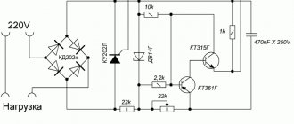
Rectifier circuit
In fact, there is absolutely no point in using complex rectifiers for a car battery. To charge such 12-volt batteries, it is enough to take a rectifier that will provide the correct voltage parameters, as well as charging current, if required. That is, in this case, beginners should not assemble multi-component electronics or automation. It’s complicated, and essentially pointless. As a result, the circuit for the rectifier used to charge the battery should be as simple as possible.
Let's take for example a rectifier that is perfect for a car battery and its charging, consisting of:
- transformer;
- switch;
- diode bridge;
- LEDs;
- ammeter;
- relay;
- buttons.
That's all, nothing more is required to assemble a rectifier for effectively charging a car battery with your own hands.
Here you can argue endlessly about which rectifier will be better for a car battery. But the fact is that beginners need to create simple but effective and safe systems. This way you can avoid unwanted problems. And professionals in this field do not need recommendations at all. They themselves know everything perfectly well.
Photo of a homemade charger for a car battery
Homemade transformer
This component is the most problematic. Typically, 1500 W transformers are used for homemade devices.
For this, any element with a wire cross-section of more than 36 mm² is used. A ready-made primary winding is taken if it was used at a voltage of 220 W. If it is not there, the car enthusiast performs the winding himself. The number of revolutions is determined by special services, where the corresponding parameters are entered. The secondary winding is removed and turned into a copper busbar. The cross-section depends on the chosen circuit: with 4 diodes - 20 mm²; 2 diodes and 2 coils - 10 mm².
The secondary winding is more difficult to complete, since it is necessary to calculate the number of turns. This is done based on the number of turns of the primary winding (Nprim). The value is calculated using the formula Nvtor = (Nperv / 220) * 12. When the data is unknown, they are determined empirically, for this:
- the secondary winding is wound (10 turns);
- measure voltage;
- parameters are determined by the formula Nvtor = (Ntime / Utime) * 12;
- remove the temporary winding and make it permanent.
Memory assembly
Step-by-step instruction:
- Make a transformer and circuit.
- Connect pins 9 and 9 together'.
- Assemble a bridge on a fiberglass plate from diodes and radiators.
- Connect pins 10 and 10 to this bridge.
- Install a jumper between 1 and 1'.
- Fix the wire with the 2' and 2' plug using a soldering iron.
- Connect fuses.
- Insert the nichrome wire into the space near the bridge, secure it on one side and connect the ammeter.
- Insulate the connections with electrical tape and place the device in the housing.
- Place the moving contact on the end of the wire and connect the battery.
During charging, the current will decrease at the end of the process. During each procedure, it is necessary to monitor the tension. It is disconnected from memory, since the indicators are always higher than the real values. The first time the device is started from an incandescent lamp. It is placed in the gap between the neutral and phase wires of the primary winding.
The main disadvantage of the described device circuit is that it does not disconnect the battery after reaching the appropriate parameters. The motorist will have to monitor the parameters using a voltmeter.
How to avoid 2 mistakes when charging a battery
It is necessary to follow basic rules in order to properly charge the battery in your car.
- It is prohibited to connect the battery directly to the mains. Chargers are intended for this purpose.
- Even if the device is made with high quality and from good materials, you will still need to periodically monitor the charging process to avoid troubles.
Following simple rules will ensure reliable operation of self-made equipment. It is much easier to monitor the unit than to spend money on components for repairs.
The simplest battery charger
It’s also important to know: 3 nuances about operation
The homemade product differs somewhat in its method of operation from the factory version. This is explained by the fact that the purchased unit has built-in functions that help with operation. They are difficult to install on a device assembled at home, and therefore you will have to adhere to several rules during operation.
- A self-assembled charger will not turn off when the battery is fully charged. That is why it is necessary to periodically monitor the equipment and connect a multimeter to it to monitor the charge.
- You need to be very careful not to confuse “plus” and “minus”, otherwise the charger will burn out.
- The equipment must be turned off when connecting to the charger.
By following these simple rules, you will be able to properly recharge the battery and avoid unpleasant consequences.
Starter output parameters
The current consumed by a passenger car starter when rotating the crankshaft depends on the make of the car and is 80-100 A at a voltage of 12 V. However, to set it in motion, the starter consumes up to 200 A for a short time. Therefore, in workshops to start passenger car engines, devices with a power of P = 12Vx200A = 2400W are used. The parameters required to start trucks depend on the specific vehicle model.
At home, the device is connected in parallel with the battery. Its power is enough for a choice of 1500 W at a current of 125 A and is determined by the power of the starter charger transformer. The wrapping pattern can be simple or with a middle.
Information! Some devices in the store are only rated at 700 watts and 60 amps.
Boot device
The starting equipment consists of three parts:
Advice! To connect the device to the battery, you can use cables from the cigarette lighter.
Manufacturing a step-down transformer
The most difficult part of this device to manufacture is the transformer for the starter charger. The most popular are homemade starting-charging circuits using a 1500-watt transformer.
Transformer design
Since any transformer with a magnetic core cross-section of at least 36mm² is used. This is enough for a 1.5 kW device.
The primary winding of the starter transformer is used ready-made if it is designed for a voltage of 220 V or rewound with copper wire with a cross-section of 1.5-2 mm². In its absence, the required number of revolutions is determined from tables or using online calculators.
The secondary winding is removed and the required winding is rewound with a copper busbar. Its cross section depends on the rectification scheme used:
When choosing aluminum winding wires, their cross-section is doubled.
Important! If you take a magnetic core with a larger cross-section, this will increase the power of the device, but will lead to a proportional increase in the cross-section of the winding wires and a decrease in the number of turns in the coils.
Secondary winding calculation
To wind the secondary winding of a starting transformer for a car with your own hands, you need to determine the number of turns. This depends on the number of turns in the primary winding Nprim. If known, the required number is determined by the formula Nvtor = (Nperv / 220) * 12. With unknown parameters, the number of turns is determined empirically:
Advice! To simplify the work, you can wind a few more turns and, after assembling the device and measuring the output voltage, unroll them.
Answers to 5 Frequently Asked Questions
- Will I need to take any additional measures before charging the battery in my car?
– Yes, you will need to clean the terminals, since acid deposits appear on them during operation. The contacts need to be cleaned very well so that current flows to the battery without difficulty. Sometimes motorists use grease to treat terminals; this should also be removed. - How to wipe charger terminals?
— You can buy a specialized product in a store or prepare it yourself. Water and soda are used as a self-made solution. The components are mixed and stirred. This is an excellent option for treating all surfaces. When the acid comes into contact with soda, a reaction will occur and the motorist will definitely notice it. This area will need to be thoroughly wiped to get rid of all the acid. If the terminals were previously treated with grease, it can be removed with any clean rag. - If there are covers on the battery, do they need to be opened before charging?
— If there are covers on the body, they must be removed. - Why is it necessary to unscrew the battery caps?
— This is necessary so that the gases formed during the charging process can freely exit the case. - Is there a need to pay attention to the electrolyte level in the battery?
- This is done without fail. If the level is below the required level, then you need to add distilled water inside the battery. Determining the level is not difficult - the plates must be completely covered with liquid.