An electromagnetic starter is a low-voltage combined electromechanical device specialized for starting three-phase electric motors, to ensure their continuous operation, to turn off the power, and in some cases to protect the electric motor circuits and other connected circuits. Certain engines have a motor reverse function.
In essence, an electromagnetic starter is an improved, modified contactor. But more compact than a contactor in the usual sense: lighter in weight and designed directly for working with motors. Certain modifications of magnetic starters are optionally equipped with a thermal microrelay for emergency shutdown and protection against phase loss.
To control the start of the motor by closing the contacts of the device, a key or a low-current group of contacts is intended:
- with a coil for a certain voltage;
- in some cases, both.
In the starter, the coil in the metal core is directly responsible for switching the power contacts, to which the armature is pressed, pressing on the contacts and closing the circuit. When the power to the coil is turned off, the return spring moves the armature to the opposite position - the circuit opens. Each contact is located in a special arc-extinguishing chamber .
Reversing and non-reversing starters
Devices come in various types and perform all assigned tasks.
There are two types of starters:
- irreversible;
- reversible.
In a reversing starter, there are two individual magnetic devices in one housing, electrically connected to each other and attached to a common base, but only one of these starters can function - either only the first, or only the second.
The reversible device is inserted through naturally closed blocking contacts, the role of which is to eliminate the synchronous activation of two groups of contacts - reversible and non-reversible, so that an interphase short circuit does not occur. Certain modifications of reversing starters are protected to provide the same function. It is possible to switch the power phases in turn so that the main function of the reversible starter is performed - changing the direction of rotation of the electric motor. The order of phase alternation has changed - the direction of the rotor has also changed.
Carrying out preparatory work
Before connecting the thermal relay and the magnetic section, you must remember that you are working with an electrical device. That is why, in order to protect yourself from electric shock, you need to de-energize the area and check it. For this purpose, most often, a special indicator screwdriver is used.
The next stage of preparatory work is to determine the operating voltage of the coil. Depending on the manufacturer of the device, you can see the indicators on the body or on the reel itself.
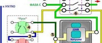
Important! The operating voltage of the coil can be 220 or 380 Volts. If you have the first indicator, you need to know that phase and zero are supplied to its contacts
In the second case, this means the presence of two opposite phases.
The stage of correctly identifying the coil is quite important when connecting a magnetic starter. Otherwise, it may burn out while the device is operating.
To connect this equipment you must use two buttons:
The first of them can be black or green. This button is characterized by permanently open contacts. The second button is red and has permanently closed contacts.
When connecting a thermal relay, it is necessary to remember that the phases are switched on and off using power contacts. The zeros that approach and depart, as well as the conductors that ground, must be connected to each other in the terminal block area. In this case, the starter must be removed. These devices are not switched.
In order to connect a coil whose operating voltage is 220 Volts, you need to take a zero from the terminal block and connect it to the circuit that is intended for the operation of the starter.
Starter capabilities
To limit the starting current of a three-phase motor, its windings can be connected in a star, then, if the motor has reached its rated speed, switch to a delta. In this case, magnetic starters can be: open and in a housing, reversible and non-reversible, with and without overload protection.
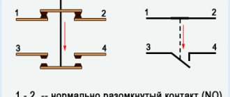
Each electromagnetic starter has blocking and power contacts. Power switches loads. Interlocking contacts are needed to control the operation of the contacts. Blocking and power contacts can be naturally open or normally closed. In circuit diagrams, contacts are shown in their normal state.
The ease of use of reversing starters cannot be reviewed. This includes operational control of three-phase asynchronous motors of various machines and pumps, and control of the ventilation system, fittings, right down to the locks and valves of the heating system. The possibility of remote control of starters is especially noteworthy if the electrical source of remote control switches the starter coils in a similar way to relays, and the latter safely connect power circuits.
MP with AC coil
If the magnetic starter is equipped with an alternating current coil, then the magnetic flux in its magnetic circuit periodically decreases to zero simultaneously with a decrease in the current in the coil. In this case, the force of attraction of the upper part of the magnetic circuit of the MP to the lower one also decreases to zero, and the return spring slightly lifts it up. Then, as the magnetic flux increases, the upper part is again attracted to the lower. As a result, the MP vibrates. In addition, due to the magnetostriction effect, a hum occurs emanating from the magnetic circuit, similar to what occurs in a transformer.
To prevent these phenomena, a short-circuit is laid at the end of the core of the magnetic circuit of the MP. a copper coil covering approximately a third of its cross-section. When the flux changes inside the coil, an alternating current is also induced in it, creating its own flux, shifted in phase relative to the main one. As a result of the interaction of these two flows, a resulting flow arises that has a constant component, the action of which is sufficient to reliably attract parts of the magnetic circuit to each other during the entire time the MF is turned on.
Design of a reversible magnetic motor
The distribution of these modifications is becoming more widespread every year, as they help control an asynchronous motor at a distance. This device makes it possible to both turn on and off the motor .
The reversing starter housing consists of the following parts:
- Contactor.
- Thermal micro relay.
- Casing.
- Management tools.
After the “Start” command has been received, the circuit is closed. Next, the current begins to be transmitted to the coil. At the same time, a mechanical blocking device operates, which prevents unnecessary contacts from starting. It should be noted here that the mechanical lock also closes the contacts of the key, this makes it possible not to keep it pressed constantly, but to calmly release it. Another important part is that the second key of this device, together with the start of the entire device, will open the electrical circuit. Thanks to this, even pressure produces virtually no result, creating additional safety.
Features of the model's functioning
Pressing the Forward key activates the coil and makes contacts. At the same time, the operation of the start key is performed by constantly open contacts of the KM 1.3 device, due to which, when the key is directly released, the power to the coil acts bypass.
After introducing the first starter, it is the KM 1.2 contacts that open, which turns off the K2 coil. As a result, when you directly press the “Back” key, nothing happens. In order to turn the motor in the opposite direction, you need to press “Stop” and turn off the power to K1. All blocking contacts can return to the opposite state, after which it is possible to drive the motor in the opposite direction. In the same way, K2 is introduced and the block with contacts is turned off . Coil 2 of starter K1 is turned on. K2 contains power contacts KM2, and K1 - KM1. A five-core wire should be connected to the buttons for connection from the starter.
Connection rules
In any installation that requires starting an electric motor in the forward and opposite directions, there is certainly an electromagnetic device with a reversible circuit. Connecting such an element is not considered as difficult a task as it might seem at first glance. In addition, the need for such tasks arises quite often. For example, in drilling machines, cutting structures or elevators, if this does not apply to home use.
The fundamental difference between a three-phase circuit and a single one is the presence of an additional control circuit and a slightly modified power part. In addition, to implement switching, such an installation is equipped with a key. Such a system is usually protected from short circuits. To do this, in front of the coils themselves in the circuit, the presence of two normally closed power contacts (KM1.2 and KM2.2), placed in positions (KM1 and KM2), is provided.
Characteristics of contactors
Typically, these devices must have the following characteristics:
The limiting, nominal value of the indicator in the main circuit.
Characteristics, type of relays, releases.
Correlation with protective devices against short circuits.
Types, parameters of acceleration regulators, automatic switches.
Type, parameter of autotransformers for 2-stage transformer starters.
Type, characteristics of starting resistance in rheostatic rotary starters.
Based on the presence of a certain number of poles, contactors can be single-pole, two-pole, or three-pole. All of them, with the exception of three-pole ones, are used for the most part in networks with direct currents, while three-pole ones are used in three-phase networks. There are also four-pole and five-pole mechanisms. The device consists of a fixed and moving contact, which depends on the purpose in a particular electrical mechanism. To connect auxiliary devices, such as a signaling circuit, an indication circuit, a circuit of certain automatic and protective devices, block contacts are located in the contactors.
The electromagnetic system, as one of the important components, includes cores, electromagnets, armatures, as well as other mechanisms that close the contacts of an electrical device.
The arc extinguishing system extinguishes the emerging electric arc during current switching. The arc is extinguished using transverse magnetic fields in chambers with an elongated opening or in chambers with deion gratings.
Reversible connection of a three-phase motor
When the switch QF1 is operating , simultaneously all three phases, without exception, are adjacent to the contacts of the starter (KM1 and KM2) and are in this state. In this case, the first stage, which represents power for the control circuit, flowing through the protection device of the control circuit SF1 and the shutdown key SB1, directly supplies voltage to the contacts under the third number, which refers to SB2, SB3. In this case, the existing contact 13NO takes on the role of the main duty officer. In this way, the system is considered completely ready for operation.
System switching during counter rotation
By using the SB2 key, we direct the first phase voltage to the coil, which relates to the KM1 starter. After this, normally open contacts are introduced and normally closed contacts are turned off. In a similar way, by closing the existing contact KM1, the effect of self-capture of the magnetic device occurs. In this case, all three phases, without exception, are supplied to the required winding of the motor, which, in turn, begins to generate rotational movement.
The created model provides for the presence of one working device. For example, only KM1 or, on the contrary, KM2 can function. The marked chain has real elements.
Changing the turning movement
Now, to give the opposite direction of movement, you should change the state of the power phases, which is convenient to do using the KM2 switch. Everything is accomplished thanks to the opening of the first phase. In this case, all contacts without exception will return to their original state, de-energizing the motor winding. This phase is considered standby mode.
Using the SB3 key activates the KM2 electromagnetic starter, which in turn changes the position of the second and third phases. This influence forces the motor to rotate in the opposite direction. Now KM2 will be the leader, and until it is disconnected, KM1 will not be used.
Basic device
The main advantages of this scheme are its low cost and ease of assembly, but the disadvantages of this scheme include the fact that circuit breakers are not intended for frequent switching of circuits; this, in combination with inrush currents, leads to a significant reduction in the service life of the machine; in addition, this scheme does not include Possibility of additional motor protection. The MP contactor turns on the control pulse that comes from the start button after it is pressed.
Voltage with a designation means different phases. Design of a magnetic starter In the absence of power, the springs press out the upper part of the magnetic circuit, the contacts are in their original state. You can remove the voltage from the outputs labeled T1, T2 and T3, which can be used to power a wind generator, battery and other devices. If the coil is powered by direct current, a dielectric spacer is placed on its core to prevent magnetized parts from sticking together.
The device can operate from a direct current source, and with single- and three-phase alternating current, the main thing is that its values do not exceed the rating specified by the manufacturer. This algorithm is implemented by closing auxiliary contacts in the MP. Pressing the power button closes the coil circuit. Contacts are divided into normally open - contacts that in their normal position, that is, before voltage is applied to the coil of the magnetic starter or before mechanical action on them, are in an open state and normally closed - which in their normal position are in a closed state. Since if the electromagnet is designed for constant voltage, then such a source will be needed.
Circuit short circuit protection
As already stated before, before carrying out the phase change process, it is necessary to stop the rotation of the motor. For this purpose, the system takes into account normally closed contacts. Because if there is a shortage of them, operator inattention would lead to an interphase direct short circuit, which can occur in the motor winding of the second and third phases. The proposed model is considered optimal, since it allows the operation of only one magnetic starter.
The connection diagram of a reversible magnetic starter is considered the core of the control, since a lot of electrical equipment operates in reverse, and this device directly changes the direction of rotation of the motor.
Reversing circuits of electromagnetic starters are installed where they are actually needed, since similar devices exist, and the reverse process is unacceptable and can cause serious automatic damage.
Principle of operation
The alternating current flowing through the main winding creates a periodically changing magnetic field. It consists of two circles of the same amplitude, the rotation of which occurs towards each other.
In accordance with the law of electromagnetic induction, the magnetic flux changing in the closed turns of the rotor forms an induced current, which interacts with the field that generates it. If the rotor is in a stationary position, the moments of forces acting on it are the same, as a result it remains stationary.
When the rotor rotates, the equality of the moments of force will be violated, since the sliding of its turns in relation to the rotating magnetic fields will become different. Thus, the Ampere force acting on the rotor turns from the direct magnetic field will be significantly greater than from the reverse field.
In the rotor turns, an induced current can only arise as a result of their crossing the magnetic field lines. Their rotation should be carried out at a speed slightly less than the field rotation frequency. Actually, this is where the name asynchronous single-phase electric motor comes from.
Due to an increase in mechanical load, the rotation speed decreases and the induction current in the rotor turns increases. It also increases the mechanical power of the motor and the alternating current it consumes.
Connection Instructions
Connection to a 3-phase network It is possible to connect 3-phase power through an MP coil operating from V.
Search on the site
Reversible circuit for connecting an electric motor through starters In some cases, it is necessary to ensure that the motor rotates in both directions. Keeping the contactor in the on state occurs according to the principle of self-retaining - when an additional auxiliary contact bypasses and is connected in parallel with the start button, thereby supplying voltage to the coil, as a result of which there is no need to hold the start button pressed. With a cross connection scheme, simultaneous operation of both starters will result in a short circuit. The coil will activate the KM1 contacts and they will close the circuit with the motor windings. Voltage with a designation means different phases.
When the armature is completely lowered, the contacts thrown by the spring are disconnected. The power supply to the control coil after connecting the magnetic starter is supplied by alternating current, but for this device the type of current does not matter. A correctly connected starter should be locked in the on position when mechanically pressing on the moving part of the magnetic circuit. The type of voltage does not matter, the main thing is that the rating does not go beyond V. Now, if you release it, the magnetic starter continues to operate until the voltage disappears or the thermal relay P for motor protection is triggered. At the same time, the starter core attracts the armature, resulting in the closure of the moving power contacts, after which voltage is supplied to the load.
But there is only one correct one. This is the so-called push-button post. You can also make a single-line graphic drawing of the connection of a three-phase electric motor to a magnetic starter via a relay. Magnetic switch. Or how to connect a three-phase motor
To a single-phase network
At home, you often have to use an asynchronous motor, but not every household has a three-phase network, so it is important to know how to connect the motor to a single-phase network. To start from one phase, an additional impulse is required; to provide it, a capacitor of the required capacity is selected. To put it simply, there should be two capacitors. One of them is the starting one and is connected in parallel with the first. The connection of the motor windings is carried out according to the “star” circuit. If the windings are connected in a different way and there is no way to change it, then it will not be possible to complete the required circuit.
It will be interesting➡ Chip NE555: Connection circuit and characteristics
In order for the reversible circuit to function, it will be necessary to switch the power that comes from the capacitors between the poles. You will need two switches and one non-fixed button. One of the switches will be responsible for supplying voltage to the engine power circuit. The second switch must have three positions. In one of them it will be turned off, and in the other two it will change the power supply from the capacitors to the windings. A non-fixed button will additionally connect a second capacitor when the engine starts.
The two terminals of the capacitor are connected to each other. The start button is connected to the other two. The middle terminal of the three-position switch is connected to the capacitors in the place where they are connected to each other. The other two pins are connected to the motor terminals, which receive power. Capacitors are connected to the output of the winding, which is used for starting. The power button is placed in the break of the phase wire.
To power the entire mechanism, it is necessary to supply power to the motor circuit using the main switch. After this, the direction of rotation of the engine is set using a three-position switch. Next, the start button is pressed until the engine reaches operating speed. If there is a need to change the direction of rotation, then you will need to de-energize the engine and wait until it stops completely, switch the three-position toggle switch to the opposite extreme position and repeat the process.
Electric motor windings
Laying windings in the stator of a single-phase electric motor
The design of any single-phase electric motor requires the use of at least three coils. Two of them are stator structural elements connected in parallel. One of them is working, and the second serves as a launcher. Their terminals are located on the motor housing and are used to connect to the network. The rotor winding is short-circuited. Two of them will be connected to the network, the rest are used for switching.
You can visually identify the working and starting windings by the cross-section of the wire: for the first of them it is noticeably larger. You can measure the resistance with a tester by connecting it to the terminals: at the working winding its value will be less. As a rule, the resistance of the windings will be no more than several tens of ohms.
General diagram of electric motor reverse
Various types of three-phase asynchronous electric motors are widely used in industry and agriculture. They are installed in electric drives of equipment and serve as an integral part of automatic devices. Three-phase units have gained popularity due to their high reliability, simple maintenance and repair, and the ability to operate directly from the AC mains.
The specific operation of devices operating with electric motors requires a change in the direction of shaft rotation, called reverse. For such situations, special circuits have been developed, which include additional electrical devices. First of all, this is an input machine that has the appropriate parameters, contactors (2 pcs.), a thermal relay and controls in the form of three buttons combined into a common push-button station.
In order for the shaft to start rotating in the opposite direction, it is necessary to change the phase arrangement of the supplied voltage. Constant monitoring of the voltage supplied to the electric motor and contactor coils is necessary. The direct implementation of reverse in a three-phase motor is carried out by contactors (CM) No. 1 and No. 2. When contactor No. 1 is activated, the phases of the incoming voltage will be located differently than when contactor No. 2 is activated.
To control the coils of both contactors, three buttons are provided - FORWARD, BACK and STOP. They provide power to the coils depending on the phase arrangement. The order in which the contactors are turned on affects the closure of the electrical circuit in such a way that the rotation of the motor shaft in each case occurs strictly in a certain direction. The BACK button only needs to be pressed, but not held, since it itself turns out to be in the desired position under the action of self-retaining.
All three buttons are locked to prevent them from being activated at the same time. Failure to comply with this condition may result in a short circuit in the electrical circuit and equipment failure. To block the buttons, a special contact block located in the corresponding contactor is used.
Operation of control circuits when the engine rotates to the right
To set the motor to rotate in the opposite direction, it is enough to swap any two supply phases, for example, “B” and “C”. This is exactly what the KM2
.
But before you press the Right
” and set the engine to rotate in the opposite direction, you need to use the “
Stop
” button to stop the previous rotation.
In this case, the circuit will break and the control phase “A” will stop flowing to the coil of the KM1
, the return spring will return the core with contacts to its original position, the power contacts will open and disconnect the motor
M
from the three-phase supply voltage. The circuit will return to the initial state or standby mode:
Press the SB3
and phase “A” through the normally closed contact
KM1.2
is supplied to the coil of the magnetic starter
KM2
, the starter is triggered and through its contact
KM2.1
stands on its own.
With its power contacts KM2
the starter will switch phases “B” and “C” in places and the motor
M
will begin to rotate in the other direction.
In this case, contact KM2.2
, located in the power supply circuit of the
KM1
, will open and will not allow the
KM1
to turn on while the
KM2
.
This is interesting: How to choose a lamp for your apartment: this is useful to know