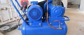
Increasing the factory setting of 1.5 atmospheres will reduce the reserve volume and increase the pressure in the system. In other cases, reconfiguration is usually not necessary. In addition, the mechanical design is capable of maintaining a comfortable pressure in the system. If you turn it and twist it, it increases, if you unscrew it, it falls. The main characteristic of such a device is the nominal operating pressure, which varies within 1.0 bar. How to connect a pressure switch. This is the operating principle of the electromechanical version of the pressure switch; there are also newer electronic models.
Setting up the pumping station consists of the following steps: Turn on the water supply and use a pressure gauge to fix the barrier to start and stop the pump. How to install a pump to increase water pressure in an apartment.
That is why it is installed next to the hydraulic accumulator.
Therefore, installing reliable and high-quality filters into the system, especially when drawing water from sand wells, will not only improve the quality of drinking water, but will also ensure reliable and uninterrupted operation of pumping equipment. Setting up the relay is the very last, third stage.
Then it is best to use a copper two or three core wire with a core diameter of 1.
Pressure switch IBO PC-9 and Omnigena Z. Review and configuration.
Purpose
The water pressure switch is designed to control the amount of liquid in the system. For this, a system with a pump and a hydraulic accumulator is used, which can be supplemented with a water presence sensor.
Rice. 1. Purpose of the water pressure switch
The pump in the water supply system can continuously supply water pressure to the main line, filling the expansion tank. The more liquid accumulates in the container, the higher the pressure. Due to the fact that the amount of accumulated water in the expansion tank is periodically consumed according to domestic needs, the need to restart the compressor unit is tied to the pressure in the system. Therefore, the main purpose of the water pressure switch is to supply and turn off power to the pump, depending on the achievement of the limit values of the measured parameter.
The measurement process will differ depending on the design features of the specific relay type. To understand the principle of operation, let us consider in more detail the design of the most common type of logical element for household pumps.
Using a third-party analog pressure sensor
Rarely, but still there are situations when, for some reason, it is not possible to use a specialized sensor in a circuit, designed to work specifically with Arduino. For example, it is impossible to find it immediately in nearby electronics stores, and the wait for the package is long. The solution may be pressure sensors used in automotive electronics. They can also be connected directly to the microcontroller.
An example is WABCO 4410400130, a sensor of the specified type, used on heavy-duty trucks. The only thing that requires attention in the presented circuit is that the element has power supply separately from the Arduino. In the latter, there is simply no +24 V required to start the sensor. Therefore, it is necessary to use an additional power supply unit with correct and sufficient power characteristics - 8–32 V DC, with a minimum of 400 mA power.
As for connecting the sensor directly to the microcontroller board, its output is no more than 5 V. And the greater the pressure, the less current will flow to the analog contacts of the logic device. But, just in case, it is recommended to check the initial output with a multimeter in order to control the possibility of “breaking through” the sensor, with the emergence of circumstances of unimpeded connection of OUT with the minus or plus of the line supplying the detector.
An example sketch for obtaining information from an analog sensor: #include LiquidCrystal_I2C DISPLAY (0x27, 16, 2); #define Detector_Pin 0 #include void setup() { DISPLAY.init(); DISPLAY.clear; AnalogReference(DEFAULT); DISPLAY.setCursor(0,0); DISPLAY.print("Data:"); } void loop() { static int AVC = 0; AVC = (AVC * 3 + AnalogRead(Detector_Pin))/4; float v = AVC * 5.0 / 1024.0; float ObtainedValue = (v - 0.5) * 10/4; DISPLAY.setCursor(0,1); DISPLAY.print(" "); DISPLAY.setCursor(0,1); DISPLAY.print(ObtainedValue); }
Now, regarding the data obtained at the output of the sketch. It is necessary to gradate them using a classic pressure gauge, assessing what numbers come from the sensor at different pressures and enter the appropriate formula into the body of the program.
And finally, technical specifications of WABCO 4410400130, for comparison with similar Arduino sensors:
- Type: piezo element
- Power: 8–32 V
- Operating temperature: −40..+80 °С
- Measuring range: 0 to 10 bar
- Accuracy: 0.2–0.3%
- Ultimate burst pressure: 16 bar
Device
Structurally, the water pressure switch can be electronic or mechanical. The first option is more compact and all processes in it are carried out using an electronic circuit. The second type of equipment is more widely used in everyday life due to its simplicity and accessibility. As a rule, mechanical models are not much inferior to electronic ones when installed in a home water supply system, so we will consider just this option as an example.
The entire device consists of three component blocks - hydraulic, mechanical and electronic, as shown in the figure below:
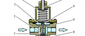
Rice. 2. Water pressure switch device
All blocks are reported into a single system, where changes in the parameters of the measured medium are displayed on each of them. However, it is more convenient to consider the design separately for each block.
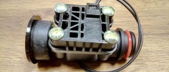
The hydraulic unit is represented by a movable sensing element fixed in the flange and bellows. In accordance with clause 4.1. GOST R 55023-2012 such an element can be a membrane, piston or other movable device.
Rice. 3. Components of the electrical and mechanical unit of the water pressure switch
The electronic and mechanical unit are represented by the following components:
- Terminals for connecting the cores of the supply wires - in this case there are two groups of terminals, one of which allows you to secure the phase, neutral and protective conductors from the distribution network. The second group of terminals is used for the outgoing power supply line to the pump.
- Couplings - used to enter the cable into the pressure switch. One of the couplings is designed to enter the cable from the distribution network, and the second is to supply power to the pump.
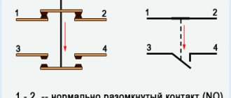
- Contact group - driven by the mechanical force of levers and a spring mechanism. It turns on and off depending on the state of the sensitive element.
- Spring drive - responds to physical deformation of the sensing element. As a result of reaching the threshold value, it moves the rod, which switches the contacts.
- Regulators - in most models, they allow you to adjust the maximum and minimum shutdown limits. Designed to adjust water pressure parameters in the circuit.
- Base – serves as a base for securing all relay elements. Depending on the model, it is made of metal or polymer. Provides strength and reliability of the structure.
The entire structure is placed in a protective housing, which prevents debris and moisture from entering the device. Depending on the climatic version, it has a different design and composition of components.
Characteristics of the hydraulic relay
The main parameters of any pressure switch are its operating temperature ranges and pressure characteristics adjustments.
Some units are designed not only to operate in water supply lines, but also to operate in the heating and hot water supply system of a private home. In this case, their operating temperature range reaches 95 °C, which is much higher than the standard threshold of 40 °C.
Regarding pressure characteristics, for individual houses with no more than three storeys, it is quite enough to use a device with an upper threshold of 5 - 7 bar to create a comfortable pressure of 3 bar on high floors.
A wide range of hydraulic relays are produced with such parameters; if necessary, it is not so difficult to find a device with a higher response threshold of up to 20 bar.
Almost all installed devices indicate their degree of protection against the penetration of foreign substances IP. Digital index 44 indicates that the devices are protected from getting inside objects larger than 1 mm, as well as drops and splashes from any angle.
The relay characteristics also indicate the current in amperes for which it is designed. The device should be selected in such a way that this figure exceeds the maximum current consumption of the pump.
When installing a hydraulic relay, take into account the dimensions of its threaded connection pipe. It is usually equipped with an external or internal thread, an American-type union nut, measured in inches, the main standard sizes are 1/4, 1/2 and 1 inch.
Rice. 5 Electronic relays
Principle of operation
To consider the operation of the water pressure switch for the pump, let’s look at the diagram in which it performs its direct functions. If we consider the existing water supply system in a private house, its structure will look like this:
Rice. 4. Operating principle of the water pressure switch
As you can see in the figure above, a submersible pump, through a check valve and a water supply system, fills the accumulator and supplies water to the water supply system. The pump itself is supplied with power through a pressure switch connected to the open circuit. The sensitive element of the relay is discharged into the pipeline through a tee (in some situations, a five-terminal fitting can be used instead of a tee). The logic of work is organized as follows:
- When the pump is turned on in the network, the pressure in rubles is at zero. The relay membrane is at the minimum mark, so its contacts are closed. Through the contact group, voltage is supplied to the pump windings, and water enters the pipeline.
- As the water supply system and expansion tank fill, the water pressure increases proportionally. The membrane in the tee will gradually absorb increasing fluid pressure.
- When the accumulator is filled and the maximum pressure limit in the system is reached, the sensitive element of the relay is deformed under the influence of water. Due to which the rod will move through a spring-lever mechanism and shift the contact group to the opposite position. The power supply to the pump will stop, and the maximum pressure level will be established in the system.
- As soon as a tap or shower is opened in the house, water will begin to flow out of the system and the accumulator, as a result of which the pressure will begin to decrease linearly. As soon as the water level reaches a minimum point at which the pressure drops below the established limit, the membrane deforms again. As a result of deformation of the sensing element, the rod will move the contact group to the opposite position. The contacts again close the power supply circuit of the pump, which will begin pumping water into the system.
The cycle of switching contacts of the water pressure switch is repeated as the set pressure limits for the transported resource are reached. However, it should be noted that if there is no water in the well or if the pipe breaks, the pressure switch will not respond to the damage, and power will be continuously supplied to the pump. This situation can become an emergency, therefore, to prevent premature wear of the elements and failure of the pump, a dry-running relay is additionally installed.
Some models
Now there is quite a large selection of pressure switches on the domestic market. Here you can find models from both Russian and foreign manufacturers. These include:
- PROMA-IDM is a universal regulator with which you can adjust the pressure of gas, air and liquid. The device body is made of plastic and is installed in a 48×96 mm hole. The converter has: four fixed ranges, improved metrological parameters, excellent interference protection, the ability to mount directly on a pipe, ambient temperature control, and so on.
- Grundfos FF is a pressure switch from German manufacturers designed for automated water supply systems at home, cottages and other facilities. The maximum setting range is from 0.5 to 8 atm, the minimum is from 0.2 to 7.5 atm. The relay can be installed in any convenient position. The device operates from a 220 V electrical network.
- SMS-PC F ¼ is an inexpensive relay regulator from a Russian manufacturer. The device is designed for operation in a pressure range from 1 to 6 bar. The electric pump starts at 1.4 bar and switches off when it reaches 2.8 bar.
- PC-58 - electronic relay is installed on the pressure water supply. The device turns off the pump in the following cases: there is no water in the system, the liquid supply stops as a result of a blockage, when water collection stops. The system can install a pump with a maximum power of 2.2 kW, the adjustment range is from 0.5 to 6 bar.
Before purchasing a device, there are several important points to consider. If you buy a relay for an autonomous system, then in this case a household device is better suited. This is due to the same indicators of key parameters of systems where the operating pressure is in the range from 1.4 to 2.8 atm. In this case, the reserve must be at least 2 atm, as this will prevent rapid wear of the membrane and extend the service life of the device.
Connection diagrams
Since we have examined the principle of connecting a water pressure switch to a water supply system, now we will analyze the basic principles of electrical connection.
Rice. 5. Connection diagram for water pressure switch
The relay is powered from a 230 V network; from the electrical energy meter, the phase and neutral conductors are supplied to the input of the logical element. A wire is also supplied to the input from the protective grounding bus. Three wires are also output from the relay to the pump: protective, neutral and phase to supply power to the compressor unit. If we consider the device itself, the connection principle is as follows:
Rice. 6. Pressure switch pinout diagram for connection
To protect people from electric shock and to prevent fire from short circuits, a diffautomatic device is installed in the power supply circuit of the pump. But it can be replaced with a UDT and a conventional circuit breaker. In addition, a dry running relay can be installed in the circuit, then the connection will be made as follows:
Rice. 7. Connection diagram via dry running relay
Data collection
My local server, which has been successfully collecting dust in the garage for 7 years now, has everything I need: mqtt server, video server (motion), mongoDB and Flask.
To write data I use mongoDB + Flask combination. You can send data directly from the ESP8266 (honestly, I haven’t tried to use this library yet), or you can “send” the data into Flask via an http request, perform the necessary manipulations and put the data in “stacks” in the database. This is not entirely productive, but it does provide an opportunity for data preprocessing. Fuck it, let something remain for your optimization. A software pie for everyone.
There is no point in describing the processing and storage of data in Flask\mongoDB, since this is beyond the scope of this article, and you are already quite tired. I would also like to mention a mobile application for reading data via the mqtt protocol.
MQTT Dash is the most worthy application that supports the MQTT protocol
For as long as I can remember, I have been using the coolest application that directly supports the MQTT protocol (only for Android users). Author - if you read the habr - from the bottom of my heart, thank you very much and continue to develop the project and fix bugs. You are handsome. The rest of the applications nervously smoke on the sidelines. If anyone is ready to object, you are welcome to comment. Thanks to the author for the opportunity to use full functionality without advertising. Application link https://play.google.com/store/apps/details?id=net.routix.mqttdash
If you use a closed MQTT server of any online service (don’t even try an open one), or use your own server, as in my case. Then you can set up the MQTT Dash application and subscribe to your reading/control channel.
Setup and adjustment
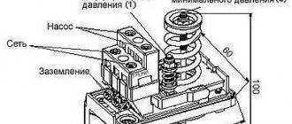
The water pressure switch is adjusted using two nuts located on top of the springs inside the device body. The first nut is responsible for adjusting the lower pressure limit. The second nut allows you to set the difference in pressure limits for switching equipment.
Rice. 8. Setting and adjusting the water pressure switch
The adjustment is made with the power off. During the idling phase without water, the switching limit is set. The lower limit must be selected so that the pressure is at least 10% greater than at idle. It is also not recommended to select the upper limit no more than 80% of the nominal value.
Transition to a new pressure switch v2.0 – MicroPython based on ESP8266
And why couldn’t I sleep...
Everything would be fine... I would go to smoke the tandoor and fry pilaf, but no, my soul is eager to fight, and even with ESP8266 , and MicroPython “smeared”. And everything in the house is on them, controlled, and via the phone. It's nice how