Voltage transformer - designed to reduce the primary voltage to values convenient for measuring instruments and relays, as well as to separate measurement circuits and protection from high voltage primary circuits. Used in AC circuits with a frequency of 50 or 60 Hz with rated voltages from 0.22 to 750 kV.
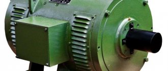
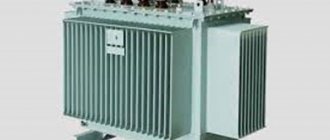
High voltage transformer (left) and low voltage transformer (right)
Principle of operation
It consists of a steel core composed of electrical steel sheet plates, a primary winding and 1 or 2 secondary windings (the design of a specific device can be found in the manufacturer’s passport or catalog).
As a result of manufacturing, the required accuracy class must be achieved in terms of:
- amplitude,
- corner.
The operating principle of a voltage measuring transformer is no different from a power step-down transformer or a current transformer.
Let us once again describe the operation of the current transformer. An alternating current passes through the primary winding; this current forms a magnetic flux that penetrates the magnetic circuit and the HV and LV windings. If a load is connected to the secondary winding, a current will begin to flow through it, which arises due to the action of EMF (electromotive force). EMF is induced due to the action of magnetic flux. By selecting different numbers of turns of the primary and secondary windings, you can obtain the desired output voltage.
Transformer operating principle
Such devices operate only on alternating voltage. If a constant voltage is applied to the VT, because EMF will not be created by a constant magnetic flux.
How to choose a step-down transformer
Reactive power in var. Short circuit experience The “short” circuit experiment is carried out at a reduced supply voltage, since the current in the transformer windings can exceed the rated values when the voltage increases.
But the latter vectors cannot produce a closed equilateral triangle. The triangle-delta connection makes it possible not to interrupt the operation of the line if one of the phases is damaged, if the transformation occurs with the help of three single-phase or one armored three-phase transformer. In these cases, simply disconnect the damaged transformer or damaged winding without disconnecting the other two from the line.
For example, standards: It concerns the transformation ratio. The primary winding is made with a larger cross-section and fewer turns than the secondary winding, often in the form of a feed-through bus.
Let's set the position of the voltage vectors of the primary winding with triangle ABC. It should be noted that even with a grounded neutral, the insulation may be subject to a voltage greater than the phase voltage if the neutral is grounded through a resistance. A feature of the primary transformer winding is its serial connection into the measured electrical circuit.
Single-turn models of current transformers are represented by varieties that do not have an individual primary winding or with an individual primary winding. In the diagram in Fig.
In this case, the transformer with a higher secondary “no-load” voltage becomes overloaded. Current transformers - device and circuit assembly.
Decoding TN
Explanation of markings:
- N - voltage transformer;
- T - three-phase;
- O - single-phase;
- C - dry;
- M - oil;
- K - cascade or with correction;
- A - anti-resonance;
- F - in a porcelain case;
- I — Isolation control;
- L - in a molded epoxy body;
- DE - with a capacitive voltage divider;
- Z - with a grounded primary winding.
Also read: Three-phase oil transformer - TMF
Transformation ratio
Transformation ratio - shows how many times the primary voltage value increases or decreases.
Formula for calculating the transformation ratio
Secondary voltage
Voltage on the secondary winding:
- 100 V,
- 100/√3 V,
- 100/3.
Accuracy classes
Accuracy classes:
- 0,1;
- 0,2;
- 0.5 – used for measurements;
- 1,0;
- 3,0;
- 3P or 6P – designed for protection, control, automation or alarm.
The rated power of transformers for any accuracy class should be selected from the range (VA): 10; 15; 25; thirty; 50; 75; 100; 150; 200; 300; 400; 500; 600; 800; 1000; 1200.
Where can I get the original transformer?
The easiest way is to pick up a ready-made transformer on the radio market, if, of course, it is available in your city. There you can also agree on rewinding the transformer. But both transformers and services for rewinding them are quite expensive.
The picture shows part of a tray at a radio market where you can buy transformers in the city of Cishinau (Chisinau).
If you have some unnecessary equipment lying around in your barn or on your balcony, then there are probably transformers in it. Any dismountable network transformer is very easy to modify to suit your needs. The most important thing is that its overall power is enough.
If the power of the transformer is less than required, then under load the output voltage of the transformer may drop significantly. But this is also not a problem, since microcircuits such as TDA2030, TDA2040 and TDA2050 can operate with a significant reduction in supply voltage, namely: ±6, ±2.5 and ±4.5 Volts, respectively.
It is unlikely that the secondary windings of the found transformer will be suitable for current and voltage, but the primary winding is already designed for the voltage of the lighting network and this is the best help, since it is much easier to rewind the secondary winding than the primary.
Well, if this is a standard unified transformer, then by its name you can accurately determine the voltages and maximum permissible currents of the secondary windings. Such transformers cannot be disassembled, so before buying one, you need to check the name with the data in the directory.
At the end of the article there is a link to a reference book in which you can find detailed information about most unified transformers of Soviet and post-Soviet production.
If it is a transformer without identification marks, then the probability that it will have to be rewound will tend to 99%. It's not worth paying a lot for such a trans.
When purchasing a transformer with a ring magnetic core, you should keep in mind that not every transformer can be disassembled without damaging the primary winding.
- Suitable for replacing the secondary winding.
- It is necessary to wind the primary winding.
- It is necessary to wind the primary winding.
Return to top menu
Types and classifications
Main classifications of transformers:
- By number of phases.
- Based on the presence or absence of grounding of the output,
- According to the principle of action.
- According to the number of stages of transformation.
- By the presence of a compensation winding or a winding for monitoring network insulation.
- By type of insulation:
- According to design features.
Old 3-phase oil transformer
Installation location:
- outdoor,
- internal,
- built into the power transformer,
- installation as a separate element.
The main features of transformers and their designations are given in the table:
A three-winding transformer should be made with two secondary windings:
- basic,
- additional.
How to check a current transformer: practical experience of an experienced relay operator
Let's return to the design of the TT and imagine everything that can be damaged in it and interfere with normal operation. This:
- breakdown of the dielectric layer between the windings, as well as to the housing or magnetic circuit;
- damage to the insulation between the turns of the secondary winding, which will lead to an interturn short circuit and a violation of the transformation ratio;
- mixing up the winding direction of the windings during installation due to errors in markings or personnel inattention;
- mechanical wear of contacts;
- wire breaks.
All CT checks are based on taking into account the possibility of the occurrence of these defects and are designed to detect their occurrence. Initially, an external inspection is always performed to visually identify external damage.
Checking current transformer insulation: what to look for
Completely assembled current circuits must have insulation of at least 1 megaohm (MΩ). To measure it, special devices are used - megohmmeters. The requirements for their design are specified in the technical documentation for the TT. In the vast majority of cases, their output voltage is 1000 volts.
Insulation measurements cannot be performed with instruments not intended for this purpose, for example, a modern digital multimeter. They have low output signal power. It will not reveal hidden defects.
A megohmmeter that has passed metrological verification and insulation tests is allowed for measurements.
They measure electrical resistance:
- housing relative to all windings;
- each winding relative to all others.
The simplest and most reliable method of direct CT testing: loading under real load
A standard transformer switching circuit is assembled. Its primary winding is connected to the power circuits, and the secondary winding is connected to the load. Precision measuring instruments are installed in both windings: current clamps or ammeters.
Voltage is applied to the power circuit so that a current I1 flows through it with a value from 0.2 to 1.0 of the nominal value. Instrument readings are taken in all windings.
Based on the measurement results, divide the current value of the primary winding by its value in the secondary: calculate the transformation ratio. If the calculated CT matches the specified technical data sheet, a conclusion is made about the serviceability of the CT.
When loaded, the transformer operates in real conditions. According to safety rules, its secondary winding must be grounded . Don't neglect this requirement.
If several secondary windings are mounted on a CT, then all of them must be reliably short-circuited or connected to measuring instruments before loading.
The magnetic cores of many high-voltage transformer transformers require grounding. They have a special clamp on the terminal block with the appropriate markings. This requirement also cannot be ignored.
Loading with an ammeter in the secondary circuit does not allow identifying defects associated with violation of the polarity of the winding connections. But, the use of a volt-ampere phase indicator (VAI) with a current clamp will help measure the angle of deviation of the current vector from the origin of coordinates and make a reliable conclusion.
Unfortunately, in practice it is often quite difficult to use the loading method. Therefore, TTs are checked in other ways.
Connection diagrams
Connection diagrams for single-phase voltage transformers:
Connection diagrams for three-phase voltage transformers:
Diagrams and groups of connections of windings of three-phase three-winding transformers with main and additional secondary windings
Also read: Pulse transformer
Transformer types
There are different types of step-down TN. The usual and most common is single-phase for a 220 V network. There are also two- and three-phase for 380 V. The most standard composition: two windings and a laminated core made of electrical steel.
Certain types of VTs are equipped with 1 winding - these are autotransformers, they can also step down / step up. In this case, there are at least 3 conclusions. A 220 V connection is made to one pair of contacts, and the output value is taken from one of the input pairs of terminals and from the other that remains free. But autotransformers cannot be used in wet rooms, since the coils in them are connected, that is, the consumer is also connected to 220 V.
Connection diagrams for measuring voltage transformers
The connection diagram for a single-phase voltage transformer is shown in Fig. 1, a. Fuses FV1 and FV2 protect the high voltage network from damage to the primary winding of the TV. Fuses FV3 and FV4 (or circuit breakers) protect the TV from damage to the load.
Connection diagram of two single-phase voltage transformers TV1 and TV2 in an open delta (Fig. 2). Transformers are connected to two phase-to-phase voltages, for example UAB and UBC. The voltage at the terminals of the secondary windings TV is always proportional to the phase-to-phase voltages supplied from the primary side. A load (relay) is switched between the secondary circuit wires.
The circuit allows you to receive all three phase-to-phase voltages UAB, UBC and UCA (it is not recommended to connect a load between points a and c, since additional load current will flow through the transformers, causing an increase in error).
Rice. 1. Circuit diagram for connecting a voltage transformer
Rice. 2. Connection diagram of two single-phase voltage transformers in an open delta
Connection diagram of three single-phase voltage transformers in a star, shown in Fig. 3, is designed to obtain phase voltages relative to ground and phase-to-phase (line-to-line) voltages. The three primary windings of the TV are connected in a star. The beginnings of each winding L are connected to the corresponding phases of the line, and the ends X are combined into a common point (neutral N1) and grounded.
With this connection, the phase voltage of the power transmission line (PTL) relative to the ground is supplied to each primary winding of the voltage transformer (VT). The ends of the secondary windings of the transformer transformer (x) are also connected into a star, the neutral of which N2 is connected to the zero point of the load. In the above diagram, the neutral of the primary winding (point N1) is rigidly connected to the ground and has a potential equal to zero; neutral N2 and the load neutral associated with it will have the same potential.
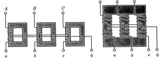
How three-phase current is transmitted
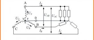
The primary power source in most cases is the electrical network. Its voltage is presented as a sinusoid with a frequency of 50 Hz. However, in cases where power transmission lines are long, the transmitted energy is radiated into the surrounding space, which leads to additional losses. Therefore, three-phase voltage is used in high-power power supply circuits.
In order to reduce radiation, the sum of the voltages on all three phases must be zero at any time. For this purpose, the sinusoidal voltage is shifted in phase in each wire relative to each other by 120 degrees. In this state, the transmission of electricity can be carried out in two ways: using four or three wires of the transmission line. Conditional diagrams of each option are shown in the figure.
The four-wire line allows you to supply the consumer with two types of voltage: phase (220 V) and linear (380 V). The three-wire circuit allows you to output only linear voltages. The formation of linear voltage is described using a vector diagram of phase voltages. With a positive phase alternation, they conditionally increase clockwise. To connect the windings of three-phase transformers, two main methods are used - star and delta.