ModificationInstallation methodSee Fig.PDU-T101 Installed vertically from inside the container into the hole, fixed with two nuts from the outside and inside PDU-T102 PDU-T104 PDU-T106 PDU-T121-065-115 PDU-T301 Installed horizontally from the inside of the container into the hole, fixed with two nuts from the outside and inside PDU-T302 PDU-T321-060-110 PDU- T501 Installed horizontally outside the container through a thread in the wall of the container or a boss with a G1/2” thread PDU-T505 PDU-T502 Installed horizontally from the inside of the container through a hole, fixed with a nut from the outside (a silicone sleeve is supplied with the sensor, which serves as a seal) PDU-T601-2 Installed vertically , fixed by the wire at the desired heightPDU-T601-5
Operating principle and methods of installation of float level sensors (level alarms) PDU-T:
PDU-T1xx, PDU-T3xx, PDU-T5xx:
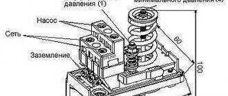
A permanent magnet in the sensor a reed switch is built into the sensor rod along which the float moves .
When the float is immersed in the liquid, it begins to move along the rod, causing the reed switch to operate and the sensor thus signals that the liquid has reached the limit level. Depending on the design, PDU-T sensors are installed horizontally or vertically in the container (see Fig. 1).
Fig.1. Example of installation of float level sensors (level alarms) PDU-T1xx, PDU-T3xx, PDU-T5xx
PDU-T601-x:
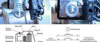
The PDU-T601-x float sensors include: a float with a contact group (NO+NC) and a ball inside, a cable of a certain length, depending on the modification of the sensor, and a weight that is placed on the cable. The cable is connected to the float through a sealed input. The weight located on the cable is intended to set the switching point for the contact state (upper level setting).
The sensor is suspended by the wire so that the float is at the height of the desired lower level of liquid in the container. In this position, the ball located in the sensor body presses on the contacts, closing one contact and opening the other relative to the common wire. The weight located on the sensor cable is lowered to the height of the desired upper level. When the container is filled, the liquid lifts the float up and when the float crosses the level at which the load is located, the ball rolls and switches the contacts to the opposite state (see Fig. 2).
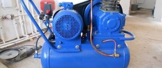
In addition to general-purpose electrical devices (starters, intermediate relays, switches, etc.), when automating pumping units, special monitoring and control devices are used, for example, pressure switches, level control relays, jet relays, etc.
Level control relays regulate the operation of pump starters and valves to control fluid levels. Such devices are capable of maintaining a set water level in containers.
Modern liquid level control relays are electronic devices, most often modular, that receive signals from sensors, process them according to a specific algorithm and switch actuators connected to the relay output contacts (solenoid valves, pump motors).
Since the maximum switched current of the output circuits of electronic level control relays usually does not exceed 10 A, magnetic starters must be used to switch powerful loads. In this system, the level relay controls the starter coil, and the starter controls the actuators of the pumping unit with its power contacts.
Electronic level control relays work with electrode and float sensors, pressure gauges, radioactive sensors, etc.
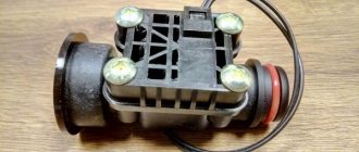
Electrode level sensor
Used to monitor the level of electrically conductive liquids. Operating principle: control of water resistance between single-pole immersed electrodes, for which alternating voltage is used.
Consists of one small electrode and two long electrodes mounted in a terminal box. One small electrode is the contact of the upper water level, and the long ones are the contact of the lower water level. The sensor is connected to the level relay and to the pump motor control circuit using wires.
If water comes into contact with the small electrode, the pump starter is turned off. When the level drops to the long electrodes, the pump turns on.
Float level sensor
Used to control the water level in non-aggressive liquids. A float is immersed in an open container, suspended on a flexible cable and balanced with a load. Two switching supports are attached to the cable, with the help of which, at maximum water levels in the tank, the rocker arm of the contact device rotates. This rocker closes contacts that turn the pump motor on or off.
In the case of a closed container, the float is connected by its lever to the axis of the lever. An axis with a certain seal is passed into the space through the wall of the housing where the contact part of the sensor is located. The wires from the contacts are routed through the wall of the container.
In most cases, suitable sensors are included with a level switch. After purchasing such a set, the consumer only needs to connect and configure everything correctly.
The following are devices that are characterized by high reliability and excellent performance parameters.
Relay RKU-1M - controls the liquid level and is used in automatic control of filling and draining containers and in protection circuits. Main characteristics: maximum switching power 3.5 W, power supply 220V, number of sensors 3, one switching contact, maximum distance from sensor to relay 100 m.
Rice. 1. Relay RKU-1M
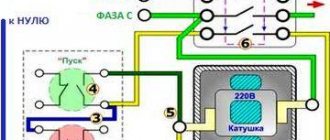
Rice. 2. Connection diagram of the pump to RKU-1M
Water level switch ROS-301 – controls three levels of electrically conductive liquids through three independent channels in one or different containers.
Rice. 3. Relay ROS-301
Single-level water level relay PZ-828 – has adjustable sensitivity, voltage – 230V, maximum current of output circuits – 16A. The device uses a changeover contact.
Rice. 4. Relay PZ-828
Rice. 5. Connection diagrams for the PZ-828 relay (directly to the load and through a magnetic starter)
The two-level relay PZ-829 is an automatic machine with adjustable sensitivity. This electronic device can control the presence of liquid at two levels.
Three-level relay PZ-830 – controls and maintains the set level of conductive liquid by controlling the electric motor of the pumping unit. A three-level automatic machine is capable of monitoring the presence of liquid at three levels, where the third level is emergency.
Rice. 6. Connection diagram for four-level level relay PZ-830
Four-level relay PZ-832 – controls and maintains the level of conductive liquids in tanks, water towers, swimming pools, etc. by controlling electric motors of pumps.
Liquid level relay equipped with three sensors EBR-1 is an electronic modular relay with a maximum distance between sensors of 100 meters. It can be used for public reservoirs (controlling the filling and draining of a container or well). Sensors supplied with a liquid level control relay are connected to the mechanism.
Main characteristics: power 3.5 VA, three sensors, maximum sensitivity 50 KOhm, power supply 230 V, operating temperature -100C – +450C, IP20 protection.
Level relay EBR-1
Relay equipped with six sensors EBR-2 is a specially designed modular monitoring relay used in wells and tanks. Also, this relay has many settings, notification when the minimum and maximum water levels are reached, the sensors are highly sensitive to the electrical conductivity of the liquid.
The kit includes six sensors. Due to its cost, this monitoring relay is an ideal option for modern water level monitoring.
Device, circuit and connection of the intermediate relay
Hello, dear readers of the site sesaga.ru. Intermediate electromagnetic relays are used in many electronic and electrical circuits and are designed for switching electrical circuits. They are used to amplify and transform electrical signals; remembering information and programming; distribution of electrical energy and control of the operation of individual elements, devices and equipment units; coupling of elements and devices of radio-electronic equipment operating at different voltage levels and operating principles; in alarm, automation, protection circuits, etc.
An intermediate electromagnetic relay is an electromechanical device that can switch electrical circuits and also control another electrical device. Electromagnetic relays are divided into permanent
and
alternating current
.
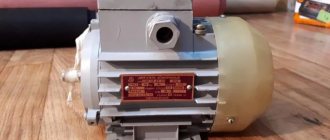
The operation of an electromagnetic relay is based on the interaction of the magnetic flux of the winding and a moving steel armature, which is magnetized by this flux. The figure shows the appearance of the RP-21 type intermediate relay.
Level determination of powders and other bulk materials
There are many types of relay switching technologies. So there are many ways to determine the level of powder and other bulk materials. With the release of Proximity Controls TFLS
(Tunable Vibrating Level Switch) and
LTS
(Tilt Switch) Series, Dwyer now offers five different spot level detection technologies for powder and other bulk materials.
These are: diaphragm , vane , tilt , capacitance and vibration .
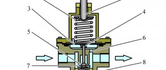
Relay device.
The relay is a coil
, the winding of which contains a large number of turns of insulated copper wire.
Inside the coil is a metal rod ( core
) mounted on an L-shaped plate called
a yoke
.
The coil and core form an electromagnet
, and the core, yoke and armature form
the relay's magnetic circuit
.
An anchor is located above the core and coil
, made in the form of a metal plate and held by
a return spring
.
Movable contacts
are rigidly fixed to the armature , opposite which are located corresponding pairs
of fixed contacts
. Relay contacts are designed to close and open an electrical circuit.
Float switch in action
Before connecting a newly purchased float switch to a pump, it is advisable to ensure that their technical characteristics are compatible. An elementary way to set up the operation of a switch for electric pumps is inside a water tank.
Serial connection diagram for float switch:
- A special sinker (from the kit) is attached to the float cable.
- The cable is securely fixed at the edge of the tank.
- The amplitude of the free movement of the float switch is adjusted to set the highest and lowest levels at which the float switch will operate.
- The float switch is connected to the pump last.
The main functions performed by a float switch:
- The float connected to the pump that performs the task of filling the tank will turn off when ascending and connect when it reaches the bottom mark.
- For an automatic station: switching on when the upper liquid level mark is reached and switching off at the lower mark (reaching the bottom of the container).
- Valves or valves with a servo drive: the switch will give a signal to close when it is in the upper position (full capacity) and will open the way for water when it reaches the lower position.
- Control room: monitoring of excess and shortage of water.
It is possible to connect two pumping devices to one float: the function of the first pump is to fill the tank when the float is located at the bottom, the mission of the second is to pump out water when it is at the top. The scheme is effective only if there is an uninterrupted supply of water to the tank. Some options for connecting switches to prevent pumps from running dry.
How does a relay work?
In the initial state, until voltage is applied to the relay winding, the armature, under the influence of the return spring, is at some distance from the core.
When voltage is applied, current immediately begins to flow in the relay winding and its magnetic field magnetizes the core, which, overcoming the force of the return spring, attracts the armature. At this moment, the contacts attached to the anchor, moving, close or open with the fixed contacts.
After turning off the voltage, the current in the winding disappears, the core is demagnetized, and the spring returns the armature and relay contacts to their original position.
Floats on mounting rod
One tank can contain up to several switches, each of which has its own function: one controls the auxiliary pump, another controls the main pump, the third acts as an emergency water level sensor, and the fourth monitors overflow.
In any case, the number of floats is determined by the number of connected pumps, as well as the need for protective devices in the system. Several floats are mounted on a special mounting rod. In its role, you can successfully use a plastic pipe securely fixed in the tank. The float switches are fixed on the rod at a distance from each other so as not to interfere with the work of the neighbor. The cable of each switch is secured using clamps. There are situations when necessity dictates the use of several rods at once for attaching floats. Taking into account operating conditions and project features, the number of float switches required to organize the work of a particular system is determined. There are two types of float switches:
- Lightweight - for a system that controls water supply or water disposal;
- Heavy - designed to control drainage or sewage pumps.
Relay contacts.
Depending on the design features, the intermediate relay contacts are normally open
(closing),
normally closed
(breaking) or
changeover
.
3.1. Normally open contacts.
As long as the supply voltage is not applied to the relay coil, its normally open contacts are always open
.
When voltage is applied, the relay is activated and its contacts close
, completing the electrical circuit. The pictures below show the operation of a normally open contact.
3.2. Normally closed contacts.
Normally closed contacts work the other way around: as long as the relay is de-energized, they are always closed
.
When voltage is applied, the relay is activated and its contacts open
, breaking the electrical circuit. The pictures show the operation of a normally open contact.
3.3. Changeover contacts.
For changeover contacts with a de-energized coil, the average
the contact attached to the anchor is
common
and closed with one of the fixed contacts. When the relay is triggered, the middle contact, together with the armature, moves towards the other fixed contact and closes with it, while simultaneously breaking the connection with the first fixed contact. The pictures below show the operation of a changeover contact.
Many relays have not one, but several contact groups, which makes it possible to control several electrical circuits simultaneously.
There are special requirements for intermediate relay contacts. They must have low contact resistance, high wear resistance, low tendency to weld, high electrical conductivity and long service life.
During operation, the contacts with their current-carrying surfaces are pressed against each other with a certain force created by the return spring. The current-carrying surface of a contact in contact with the current-carrying surface of another contact is called the contact surface
, and the place where the current passes from one contact surface to another is called
electrical contact
.
The contact of two surfaces does not occur over the entire apparent area, but only in separate areas, since even with the most careful treatment of the contact surface, microscopic tubercles and roughness will still remain on it. Therefore, the total contact area
will depend on the material, the quality of the contact surfaces and the compression force. The figure shows the contact surfaces of the upper and lower contacts in a greatly enlarged view.
At the point where current passes from one contact to another, electrical resistance occurs, which is called contact resistance
. The magnitude of the contact resistance is significantly influenced by the magnitude of the contact pressure, as well as the resistance of the oxide and sulfide films covering the contacts, since they are poor conductors.
During long-term operation, the contact surfaces wear out and can become covered with soot deposits, oxide films, dust, and non-conducting particles. Contact wear can also be caused by mechanical, chemical and electrical factors.
Mechanical wear occurs when contact surfaces slide and impact. However, the main cause of contact destruction is electrical discharges
, arising when opening and closing circuits, especially DC circuits with an inductive load. At the moment of opening and closing, the phenomena of melting, evaporation and softening of the contact material, as well as the transfer of metal from one contact to another, occur on the contact surfaces.
Silver, alloys of hard and refractory metals (tungsten, rhenium, molybdenum) and metal-ceramic compositions are used as materials for relay contacts. The most widely used material is silver, which has low contact resistance, high electrical conductivity, good technological properties and relatively low cost.
It should be remembered that there are no absolutely reliable contacts, therefore, to increase their reliability, parallel and serial connection of contacts is used: when connected in series, the contacts can break a large current, and parallel connection increases the reliability of the electrical circuit.
Instruments for measuring the level of bulk materials
Measuring the level of bulk media in containers of various shapes and volumes when automating technological processes in the food industry is a more complex task than monitoring the level of liquid media. This is due to the fact that bulk materials, when filling and emptying containers, do not have a horizontal surface, but form slopes as a result of friction and some adhesion between the particles of the bulk material. The pressure of bulk media on the bottom and walls of the container is not proportional to the height of the level, since Pascal’s law does not apply to bulk materials. Most bulk materials (especially salt, sugar, flour and the like) lose their flowability during storage, i.e. have caking properties. In addition, they can stick to the surfaces of containers and sensing elements of level transducers, which, combined with caking, leads to materials hanging on inclined and, in some cases, vertical planes. The abrasiveness of some bulk materials (grain, salt, etc.) causes increased wear of level sensors installed in bins, and lump materials can cause mechanical damage. A number of bulk materials (flour, salt, concentrated feed, sulfur, etc.) form suspended, flammable, and under certain conditions, explosive dust in containers. Therefore, electric level gauges can only be used in explosion-proof versions.
The variety of measurement conditions and characteristics of bulk media determines a large range of instruments for measuring the level of bulk materials: mechanical, contact-mechanical and float-type, hydrostatic and electrical, ultrasonic, etc. It should be noted that a number of the above discussed devices for measuring the level of liquid media can be successfully used for measuring level of bulk materials. However, commercially produced devices for monitoring the level of bulk materials do not provide solutions to the entire variety of problems that arise when implementing automated process control systems in the food industry.
Electrical diagram of the relay.
On circuit diagrams, the coil of an electromagnetic relay is depicted as a rectangle and the letter “K” with the serial number of the relay in the circuit. Relay contacts are designated by the same letter, but with two numbers separated by a dot: the first number indicates the serial number of the relay, and the second indicates the serial number of the contact group of this relay. If in the diagram the relay contacts are located next to the coil, then they are connected by a dashed line.
Remember.
In the diagrams, the relay contacts are shown in a state when voltage has not yet been applied to it.
The manufacturer indicates the electrical circuit and numbering of the relay terminals on the cover covering the working part of the relay.
The figure shows that the coil terminals are indicated by numbers 10
and
11
, and that the relay has three groups of contacts:
7 - 1 - 4 8 - 2 - 5 9 - 3 - 6
Here, under the electrical diagram, the electrical parameters of the contacts are indicated, showing what maximum current they can pass (switch) through themselves.
The contacts of this relay switch an alternating current of no more than 5 A at a voltage of 230 V, and a direct current of no more than 5 A at a voltage of 24 V. If more than the specified current is passed through the contacts, they will very soon fail.
On some types of relays, the manufacturer additionally numbers the terminals on the connection side, which is very convenient.
For ease of operation, replacement and installation of relays, special blocks are used that are installed on a standard DIN rail. The blocks have holes for relay contacts and screw contacts for connecting external conductors. Screw contacts have contact numbering that matches the relay contact numbering.
Also on the relay coils the type of current and operating voltage of the relay winding are indicated.
We’ll finish here for now, and in the second part we’ll look at the main parameters
and
connecting electromagnetic relays
, where we will analyze the operation of the relay using examples of simple circuits.
See you on the pages of the site. Good luck!
1. I. G. Iglovsky, G. V. Vladimirov - “Handbook of electromagnetic relays”, L., Energy, 1975 2. M. T. Levchenko, P. D. Chernyaev - “Intermediate and indicating relays in devices relay protection and automation", Energy, Moscow, 1968, (B-ka electrician, issue 255). 3. V. G. Borisov, “Young radio amateur”, Moscow, “Radio and Communications” 1992
Rating
(No ratings yet)
Comments0 Share:
Loading …
Similar materials
Registration of water level in a closed tank (level alarm)
Float switches are often used to indicate the level of liquid in a closed tank. The sensor contacts switch the signal lamps on the control cabinet. For these purposes, a specialized device - a level indicator - can also be used. In this case, signals from the sensors are input to the device inputs. The figure shows an example of recording the water level using the SAU-M6 level switch.
Tags: float level sensor, level relay, level switch, pump control