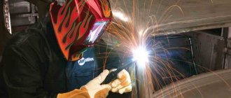
Standards for welding work
The purpose of the standard values is to regulate the quality of the work performed, the speed of completion, the time it takes to complete certain works, production standards, the energy consumption that will be required to perform the welding work, the required number of components, and the time required to perform the welding.
In addition, the control of welded joints and methods for its implementation are regulated. The requirements of the SNiP document are subject to the release of drawings and documentation, in particular, technical specifications. Particular attention is paid to ensuring safety when carrying out welding work.
SNiP consists of four parts independent from each other, which contain standards for welding work.
Rules regarding time
The standard time for welding is calculated based on the concept of the standard time for welding 1 m of a seam. A qualified welder must have the ability to independently calculate the time during which he can perform specific operational actions. The performance and productivity of the work performed will depend on the correct calculation.
When making calculations, the welder must take into account the time standards for welding work specified in SNiP. They consist of the time spent specifically on the welding process, as well as the time spent on preparatory work and various production operations.
There are three types of production operations included in the concept of norm:
- Main.
- Auxiliary.
- Additional.
The concept of the main production operation includes the provision of consumables for welding, the necessary processing of the main metals being welded and carrying out preparatory operations. Basic production welding is the welding process performed.
The auxiliary operation includes: delivery to the welding site of the parts to be welded and the selected equipment, further control of the resulting joint and its movement according to the technological process, for example, to the assembly workshop.
Additional time is taken into account for servicing the process, setting the necessary parameters on the equipment, drying the electrodes, checking the functionality of the devices used, replacing the electrodes, and applying flux. This concept may include the time it will take to deposit, if necessary.
The calculation must include time for caring for your workplace, changing into a protective suit, rest and lunch break.
When calculating, the qualifications of the performer are taken into account, which affects the speed of the welding process, and a special coefficient is applied. There are several methods for calculation, the most common of which is calculation using work units. Each unit is equated to one product being welded.
Production rate
The standardization of welding work regarding their production determines the work performed in a specified time. The unit of measurement is the number of products or the value of the weld seam in meters that have undergone the welding process in one hour or per shift. The production rate can be a component of the time rate or calculated separately.
Electricity consumption rate
SNIP for welding requires keeping records of the costs of electricity required to carry out the work. They depend on the equipment used and its power, indicated in the passport. In addition, sufficient lighting of the work area is necessary. The unit of measurement is kilowatt-hours.
Standard for components
When welding, not only time and electricity are consumed, but also components and tools. SNiP for welding work also provides for these circumstances. Components without which welding cannot be carried out include electrodes, flux, and gas.
Costs of this type include wear and tear on equipment and individual specific elements - roller guides, contact jaws and similar products. Equipment wear and tear depends on numerous factors. For example, on the material used to manufacture components, as well as on the operating mode selected and installed on the equipment.
Timing
For the convenience of carrying out calculations, SNiP for welding contains auxiliary material for faster and more convenient calculations. These include various tables. An example is the following table for standardization of welding work:
The table given as an example applies to conditions where welding is carried out on only one side and there is no bevel of the edges. In this case, the position of the seam in space and the category assigned to this type of work play a role. The thickness of the parts to be welded is of great importance, which takes into account the time standards for welding metal structures.
Welding time can be calculated using the following formula:
Where:
- t0 is the required time;
- L —seam length;
- F is the cross-sectional area of the seam;
- I is the current value;
- Kn is a coefficient characterizing surfacing.
In the indicated formula, the value 7.85 is the density of the metal. In each specific case, you should substitute your own value. To calculate the time spent on welding work in one work shift, the result of the calculation should be multiplied by the number of hours using the formula.
If gas welding is carried out, it is convenient to use the following formula:
Where:
- S —thickness of the metal to be welded;
- K is a coefficient depending on the metal. It will be different for different species.
The formula used to calculate welding time with oxygen is:
Where:
- L is the length of the welds;
- V is the welding speed.
Unified time standards for welding work are specified in the normative document SNiP. The unit of measurement can be the welding time of 1 meter of seam. Also in the calculations, a unit of measurement is used, such as the welding rate in meters per day.
Organization of the workplace for successful compliance with standards
In order for all design standards for welding work to be met, it is necessary to properly organize the place where the welder will work.
It is arranged in accordance with the recommendations of the scientific labor organization NOT. Sitting at a metal workbench should be comfortable. There should be a protective visor on top. The room must be equipped with exhaust ventilation. There must be sockets for connecting welding equipment. Safety equipment is required.
Technical part
1. Present and Rasc.
of this chapter are intended for welds made in accordance with GOST 5264-80.
2. For manual arc welding, the following work composition is provided:
1. Turning welding machines and units on and off.
2. Setting the welding current.
3. Cleaning the edges (joints) before welding from rust and dirt with a steel brush.
(New edition. Amendment dated December 18, 1990).
4. Welding seams.
5. Cleaning the intermediate and last layers of the weld from slag.
6. Inspection and measurement of the seam.
3. The standards provide for the use of the following brands of electrodes: OZS-4; OZS-21; VSF-75U; OZS-18; UONI-13/85; OZS-17N; ANO-11; VSF-65U; ANP-2; NIAT-3M; ANO-14. When using electrodes of other brands N.v. and Rasc.
multiply by the coefficients given in table. .
a - seam in the lower position of butt joints; b - seams in a horizontal position of butt joints; c - seams in a vertical position of overlap joints; d - seams in the ceiling position of T-joints and overlap joints; d - lap joint seam made in the lower position; e - joint seam made in the ceiling position; g - corner joint seam, performed in the ceiling position; h - corner joint seam, performed in the lower position.
Table 1
| Electrode brands | Coefficient to N.v. and Rasc. | № |
| ANO-5 | 0.7 (PM-1) | 1 |
| SM-11; DSK-50; OZS-22R | 0.8 (PM-2) | 2 |
| SK2-50; OZS-6 | 0.85 (PM-3) | 3 |
| ANO-6; UONI-13/55U; VSF-85; VN-48 | 0.9 (PM-4) | 4 |
| ANO-4 | 0.95 (PM-5) | 5 |
| OZS-25; UONI-13/65; OZS-24; TMU-21U | 1.1 (PM-6) | 6 |
| OUNI-13/55K | 1.15 (PM-7) | 7 |
| MR-3 | 1.2 (PM-8) | 8 |
| OZS-12 | 1.25 (PM-9) | 9 |
| UONI-13/55 | 1.3 (PM-10) | 10 |
| SSSI 13/45; OZSh-1 | 1.4 (PM-11) | 11 |
The standards provide for the use of electrodes whose diameter corresponds to the thickness of the metal being welded and the shape of the edges.
The diameter of the electrodes, depending on these parameters, is established by the technical conditions for welding.
4. For one-sided welding, weld root welding is not taken into account and is standardized according to § E22-1-9.
5. Tariffing of work should be carried out in accordance with the data given in table. 2.
table 2
| No. | Characteristics and examples of work | Type of work |
| Welding in all spatial positions of the weld, except for the ceiling | 3 | |
| 1 | Casings assemblies, heating boilers | |
| 2 | Racks, bunker grates, transition platforms, stairs, railings, decking, boiler lining | |
| 3 | Smoke pipes up to 30 m high and ventilation pipes made of sheet steel | |
| 4 | Welding of metal structures indicated in the examples of work 3 grades. with a ceiling position of the seam | 4 |
| Welding of medium complexity of machine parts, assemblies and structures in all spatial positions of the weld | ||
| 5 | Apparatuses, vessels, containers operating without pressure | |
| 6 | Frames of industrial furnaces and boilers | |
| 7 | Fastenings and supports for pipelines | |
| 8 | Masts, drilling derricks - welding in procurement shops | |
| 9 | Foundation slabs | |
| 10 | Dust-gas-air ducts, fuel supply units and electrostatic precipitators | |
| 11 | Tanks and gas tanks with a volume of less than 1000 m3 | |
| 12 | Half-timbered structures, connections, lanterns, purlins, monorails | |
| Welding of complex critical apparatus, assemblies and structures in all spatial positions of the weld seam | ||
| 13 | Apparatuses and vessels operating under pressure | |
| 14 | Span beams for bridge cranes with a lifting capacity of less than 30 tons | 5 |
| 15 | Blocks of building and technological structures made of sheet metal: air heaters, scrubbers, casings and flues of blast furnaces, separators, reactors | |
| 16 | Caissons of open hearth furnaces operating at high temperatures | |
| 17 | Columns, bunkers, rafter and sub-rafter trusses, beams, overpasses | |
| 18 | Structures of radio masts, television towers and power line supports - welding in fabrication shops | |
| 19 | Masts, drilling and production derricks - welding during installation | |
| 20 | Tanks and gas tanks with a volume from 1000 to 5000 m3 - welding during installation | |
| 21 | Tanks and gas tanks with a volume of 5000 m3 and more - welding in procurement shops | |
| Welding of particularly complex critical apparatus, assemblies and structures in all spatial positions of the weld seam | 6 | |
| 22 | Beams for working platforms of open-hearth shops, crane beams for heavy-duty cranes | |
| 23 | Span beams for overhead cranes with a lifting capacity of 30 tons and more | |
| 24 | Vacuum and cryogenic containers, caps, spheres | |
| 25 | Spherical and drop-shaped containers and coatings | |
| 26 | Ammonia synthesis columns | |
| 27 | Reservoirs and gas tanks with a volume of St. 5000 m2 - welding during installation | |
| 28 | Structures of span metal and reinforced concrete bridges |
Safety rules according to SNIP
Labor safety of welding work in construction in SNiP is specified in Part 1, which contains general requirements. The list containing the scope of application also indicates the manufacture of structures and products. The document states that before welding can begin, the work manager is obliged to check compliance with the requirements specified in the regulatory document.
The safety requirements for welding metal structures are specified in the regulatory document SNiP III-18-75. It lists the following requirements:
- steel structures must be welded using a high-performance mechanized method;
- when welding, it is necessary to be guided by the requirements of the approved technological process;
- when welding, a stable mode is required;
- the manager must have a certificate indicating that he has the right to carry out work related to welding;
- manual, semi-automatic and automatic welding must be carried out by performers with a suitable category;
- Before assembly, it is necessary to clean the metal surface in the area of operations and the surrounding area;
- when performing multilayer welding, it is necessary to clean each previous layer before applying the next one;
- should be cleaned from dirt, rust, deposits, slag and metal splashes;
- moisture should be removed from condensation;
- during semi-automatic and automatic welding, during a break in work, before resuming the process, it is necessary to clean the end of the weld;
- the place where welding is carried out should not be exposed to drafts, wind, or precipitation;
- At sub-zero temperatures, heating devices should be located near the welder’s workplace, in particular for warming hands.
Welding metal structures according to SNiP will ensure that a welded joint of the required quality and reliability is obtained.
Regulatory requirements and calculations when creating welded metal structures
According to ENiR 22 1, welding work must fully comply with the requirements and regulations of SNiP III-18-75. The standards are taken into account when carrying out repair work, as well as when constructing new facilities from welded metal structures. In addition to instructions on welding techniques, the document also contains prices for the work performed.
Creation of metal structures using the manual arc method
In order for metal products to comply with ENiR, welding work must be performed in compliance with certain stages:
- turning on the equipment and setting all parameters, including the main operating mode;
- preparation for welding of all elements and parts, thorough cleaning of the metal at the joints from traces of oil and other contaminants;
- the process of welding elements into integral structures;
- removing crusts from slags generated during the work process from welding seams;
- monitoring connections for strength, presence or absence of defects.
Depending on the shape of the edges and thickness, different electrodes are used. Often the diameter of the electrodes used is indicated in the product flow sheet or drawings made before welding. As for brands, according to ENR recommendations, welding will be of higher quality and more reliable when using electrodes marked OZS-4, 21, 18, 17N; VSF-5U and 65U; UONI-13/85; ANO-11 and 14; ANP-2; NIAT-ZM.
This list is not a strict limitation; the welder can work with other brands, while multiplying prices and standards by the coefficients indicated in the document.
The picture below shows the most common types of butt joints, which are created in different positions:
- a) in the bottom;
- b) in horizontal;
- c) in the vertical - lap seams;
- d) T-joints and overlap joints - in the ceiling;
- e) at the bottom - overlap seams;
- e) in the ceiling;
- g) corner joints in the ceiling;
- h) angular in the lower position.
Below is a table according to which you need to calculate tariffs for welding work.
Mechanized and automatic submerged arc welding
In accordance with ENiR, welding of metal structures performed directly in a workshop or on a plant premises using automatic or mechanized submerged arc welding should only occur in the lower position. The work order is as follows:
- turning on a semi-automatic device;
- thorough preparation of metal surfaces: cleaning edges, removing corrosive deposits and dirt;
- filling the flux with a powdery composition;
- installation of wire into the mouthpiece and into the wire feeding mechanism, using specialized reels for this; selection of optimal welding mode;
- work on welding elements;
- pulling out previously installed wires from all mechanisms;
- removal of slag formations;
- control and measurement of seams for compliance with parameters.
Following the requirements of ENiR 1 22 1, welding work is carried out using filler wire, the diameter of which for automatic equipment does not exceed 5 mm, for a mechanized process - 2 mm.
Tariffs for ENiR for welding work on metal structures can be calculated using the tables below.
Welding with flux cored wire
Work using flux-cored wire is performed using a mechanized technique in the same order as the two types of welding described above. Only in this version, a reel with wire wound on it is installed on the turntable of the semiautomatic device, after which the wire is installed in the electrical holder. The mouthpiece is replaced as necessary. The diameter of the wire material should not exceed 3 mm.
According to the ENiR rules, welding work on metal structures should be carried out in a lower spatial location. When welding products in a confined space or in outdoor conditions, deviations from the established norms are allowed.
Tariffs are calculated according to the table below.
Mechanized welding in a carbon dioxide environment
After turning on the device, the current strength is adjusted and the desired welding mode is selected. All parts to be welded are thoroughly cleaned of traces of dirt, dirt and rust, and the edges are cleaned. A spool of wire and a gas cylinder are installed, the hoses are purged, and after that you can start welding.
After removing the wire and removing the slag, the dimensions of the seam are measured and a visual inspection is carried out.
The table for calculating tariffs is given below.
Gas cutting
In accordance with ENiR 22 issue 1, welding work using manual gas cutting is carried out in the following order:
- gas cylinders are checked and installed;
- cutters are adjustable;
- test cutting is performed and if everything is normal, the steel is cut;
- The gas supply is shut off and the hoses are disconnected.
Mechanized gas cutting is carried out in the same sequence, only in this case it is necessary to adjust the operating mode. Below is a table used to calculate gas cutting tariffs.
What SNiP says about welding metal structures
SNiP imposes special requirements for welding work on metal structures. Compliance with them is a guarantee of obtaining a weld of proper quality. The main requirement is strength and reliability.
Welded connections of metal structures in accordance with SNiP 3.03.01-87 must be carried out in accordance with the instructions:
- In cases where there are no certificates for materials or when the warranty period for their storage has expired, it is necessary to determine the mechanical properties of butt joints. Prototypes are being tested. They are tested for static tension and bending.
- Auxiliary materials are stored in factory containers, sorted by batches, brands, and diameters. The storage area must be dry and heated.
- Coated electrodes, fluxes and cored wires must be calcined before use. In this case, it is necessary to comply with the modes specified in the technical documentation for them. Calcined materials are stored in warehouses with appropriate temperature and humidity, or in drying cabinets.
- At a certain distance from the place where the weld is located, the welder must affix his personal mark. If the work is performed by several performers, then their prints must also be available. Another identification is acceptable - drawing up diagrams on which welders put their signatures.
Requirements for welded structures made of steel:
- Welding can begin after the assembly has been checked according to the drawings for it. Tolerances must be taken into account when performing the inspection.
- Tolerances when welding metal structures must correspond to the values specified in the relevant regulatory documents.
- It is necessary to clean the edges of the weld from dirt, paint stains, grease, and rust.
- The welding mode must be stable. Deviations of ± 5% are allowed.
- The amount of calcined materials in the workplace is limited. It should not be higher than the need for them in the amount of half a working day. In the case where steel structures have high fluidity, the electrodes removed from the drying oven or immediately after the completion of the calcination process should be used within the next couple of hours.
- When welding in low temperature conditions, local heating of the action area should be carried out.
- The places where installation devices are welded to the structure are preheated.
- If sheet elements with a thickness exceeding 20 mm are welded, then in the case of arc welding, options are used that provide a reduction in the welding speed by the cooling method. These include sectional cascades - reverse-stage, as well as those with a double layer.
- When making arc welding connections made by full penetration, the root of the weld should be cleaned before starting the process.
- When there is a break in arc welding, it can be resumed after the crater and end section have been cleaned of slag.
- If the drawings provide for a concave profile, then this can be ensured by selecting the appropriate welding modes. Sanding with abrasive can also be used.
- In automated welding, the beginning and end of the welded joints must be placed outside the elements onto strips. At the end of the welding process, the strips must be removed using oxygen cutting. The use of planks is provided for in the drawings. When using arc welding, it is prohibited to extend the crater beyond the weld.
- When multilayer welding, the bead can be started after stripping the previous one. It is mandatory to remove areas with cracks.
- After welding is completed, the assembly bolts and mounting hardware should be removed.
- The quality of parts intended for fastening and tacks should not be worse than the base metal being welded.
In addition to SNiP, when welding metal steel products, it is necessary to take into account the requirements of such a regulatory document as SP welding of metal structures.
SNiP requirements for welded joints representing reinforced concrete structures:
- The dimensions of the rods, as well as the magnitude of their maximum deviations, must comply with the requirements of GOST 14098.
- If welding is performed mechanized, then direct current up to 500 A should be used.
- When performing the process using arc welding, it is advisable to use transformers.
- Before starting the welding process, the reinforcing bars should be cleaned in an interval that exceeds the weld by 10-15 mm.
- When welding reinforcement bars, if the gap value specified in the technical documentation is exceeded, it is permissible to use inserts made of material of the same class and diameter as the bars.
- The length of rods made of concrete must be at least 150 mm. When using inserts, the permissible length of the rods is at least 100 mm.
- The welded parts of the reinforced concrete structure must be rigidly fixed. Holding them with a crane is prohibited.
- After the welding process is completed, traces of metal splashes and slag should be cleaned.
- At sub-zero temperatures, the use of tack welds in cross-shaped connections of reinforcing bars is not permitted.
- Burn marks from arc welding are not allowed on the surface of reinforcing bars.
- When manual welding in the case of sub-zero temperatures, the current value should be increased, as well as preheating.
Welded joints are made depending on their spatial position and further operating conditions.
INTRODUCTORY PART
1. This issue contains standards for manual, automatic and mechanized (submerged arc, flux-cored wire, carbon dioxide) arc welding, as well as for manual and mechanized gas cutting in the manufacture and installation of building structures and industrial structures.
(New edition. Amendment dated December 18, 1990).
2. The release standards provide for the performance of work taking into account the following conditions: the quality of the work performed must comply with the technical conditions and requirements of SNiP 3.03.01-87 “Load-bearing and enclosing structures; work must be carried out in compliance with all the rules and requirements of chapter SNiP III-4-80 “Safety in construction”; workers must know and comply with all the requirements provided for in this release, arising from the specified SNiP, ensuring the required quality of work while observing safety measures.
3. The production standards provide for welding and cutting of rolled products, elements of steel structures, reinforcement and embedded products made of carbon and low-alloy structural steels at the installation site (except for Chapter and). When performing work at the assembly site (procurement shops) to N.v. and Rasc.
apply a coefficient of 0.9 (HF-1).
4. The production standards take into account the welding of joints pre-fastened during assembly with bolts or tacks.
Tack work performed during the assembly and installation of steel and reinforced concrete structures is not taken into account by welding standards and is further standardized.
Welding of previously produced non-removable tacks is taken into account by the standards and is not subject to additional payment.
P. 2 - 4. (Changed edition. Amended on December 18, 1990).
5. The standards of all chapters of the issue take into account and do not additionally pay for the transition of workers during work to a distance of up to 100 m when carrying out work at the installation site or to a distance of up to 50 m when carrying out work at the assembly site, carrying welding materials, cables, hoses, tools and small devices, moving or turning within the workplace of welded structures and products in jigs and devices or without them with a weight of structures and products up to 50 kg - manually, with a larger weight - by crane.
6. Maintenance by a welder of a gas generator (delivery of calcium carbide and water, refueling, etc.) or a welding unit with an internal combustion engine (refueling, starting, lubrication, monitoring operation, etc.) is not taken into account by the standards and, as a rule, must be done by the driver. When servicing a welding unit or gas generator by the welder himself N.v. and Rasc.
should be multiplied by 1.2 (HF-2).
7. When performing work in cramped conditions or in an awkward position to N.v. and Rasc.
release, the following coefficients can be applied: when working in trays, trenches, on trestles, scaffolding, scaffolding, from ladders, when working lying down or in a bent position in cases of difficult access to the welded joint - up to 1.25 (VCh-3); when working from hanging cradles and ladders, as well as structures and equipment, when the main means of preventing falls from a height is an installation safety belt - up to 1.5 (VCh-4).
The presence of the specified conditions for the production of work and the value of the coefficient must be established in each individual case by an act approved by the head of construction, construction and installation (repair and construction) organization or the head of the enterprise carrying out construction in an economic way, in agreement with the trade union committee.
8. When rationing welding and gas-cutting work performed at height, coefficients similar to those for rationing installation work that take into account the height of their performance should be used.
9. When welding butt joints made of steel of unequal thickness with a difference not exceeding the values indicated in the table. , rationing and payment of labor should be carried out according to greater thickness.
Table 1
| Thickness of thin steel, mm | Difference in steel thickness, mm |
| From 1 to 4 | 1 |
| St.4"20 | 2 |
| «20«30 | 3 |
| «30 | 4 |
If the difference in the thickness of the steels being welded exceeds the values indicated in the table. , rationing and payment of labor should be carried out according to a smaller thickness.
10. When welding structures with a short or intermittent seam in sections up to 0.5 m long N.v. and Rasc.
multiply by the coefficients given in table. .
table 2
| Seams | Seam length, m, up to | ||||
| 0,05 | 0,1 | 0,25 | 0,5 | ||
| Short | 1.3 (HF-5) | 1.25 (HF-5) | 1.2 (HF-7) | 1.1 (HF-8) | 1 |
| Intermittent | 1.1 (HF-9) | 2 | |||
| A | b | V | G | № | |
The volume of work performed when welding with a short or intermittent seam is determined by the sum of the segments of the actually welded areas.
11. When welding structures with a circumferential seam in a rotary position N.v. and Rasc.
multiply by a factor of 1.05 (HF-10), in a non-rotating position, multiply by a factor of 1.1 (HF-11).
12. Depending on the complexity of the work performed, for each standard several prices are given, corresponding to the category of work.
13. The standards provide for welding of lap, butt, corner and T-joints in the lower, horizontal, vertical and ceiling positions of the seam in space (see figure).
Seams in the lower position are seams located on a horizontal plane in any direction, made with an electrode lowered down.
Seams in a horizontal position are seams located on a vertical plane in the horizontal direction.
Seams in a vertical position are seams located on a vertical plane in the vertical direction.
Overhead seams are seams that are positioned so that they can only be made with an electrode pointing upward.
Seams located on a vertical plane at an angle of up to 45° to the horizontal are rated as horizontal, and at an angle of more than 45° - as vertical.
14. Production prices are calculated without taking into account additional payments for work with harmful and especially harmful working conditions.
15. Tariffing of work was carried out in accordance with the ETKS of work and professions of workers, issue 2, section. “Welding work”, approved on January 16, 1985.
Checking the quality of received connections
SNiP regulates the quality control of welded joints in sufficient detail. Control can be carried out by the welder himself or by workers specially designated for this. Another option is to seek help from special laboratories whose activities include carrying out such operations.
Before welding work begins, it is necessary to check whether the qualifications of the welders to whom they are entrusted correspond to the complexity of the task. The welder must present a work permit to perform specific welding work. If the purpose of the welding joint is of increased importance, then preliminary testing can be carried out on a sample of the same material and the same dimensions.
Before starting, it is also necessary to inspect the parts to be joined using the welding process. They must be made of material for which there are certification documents. Before starting welding, a thorough inspection must be carried out to identify defects on the parts to be welded. What the quality of parts should be is also indicated in regulatory documents, including SNiP.
Production control of welding work includes the following stages:
- Incoming control . It applies to process documentation, the design of joints to be welded, equipment used, as well as auxiliary devices and tools.
- Operational control . Welding processes and technological operations are subject to it. It is necessary to check the correctness of their implementation. Operational control also includes checking the use of equipment and compliance with safety regulations.
- Acceptance control . The quality of the welds and connections made is subject to examination.
When performing input and operational types of control, it is necessary to follow the instructions set out in the regulatory document SNiP 3.01-85. For each type of control, technical standards for welding work are applied.
Quality control of welding work begins with a visual inspection. It allows you to identify all external defects visible to the naked eye. SNiP allows the use of a high-magnification magnifying glass for visual inspection. Rejecting connections whose external defects cannot be corrected or would not be economically feasible saves time and money.
According to the requirement of SNiP, all welds without exception must be subjected to visual inspection. Templates and calipers are used to measure the defect. Before starting a visual inspection, it is necessary to prepare the surface by cleaning it.
The second popular method is capillary. The advantage of this method is its versatility. SNiP allows its use to identify defects such as cracks of various sizes and pores, as well as burns and lack of penetration. This method uses a special penetrating liquid; no additional equipment is required. A combination of the capillary method with others is allowed. Special solutions or filter suspensions can be used as a penetrating liquid.
The capillary method is divided into several varieties depending on the method of obtaining information. Before penetrant testing can begin, the area being tested must be thoroughly cleaned. Various solvents are used for it. The control itself is carried out by applying special indicators to the surface of the welded joint.
The tightness test is carried out by monitoring the tightness. A properly executed connection should not allow passage of either liquid or gaseous substances. If there are through-through defects, this requirement is not met. Requirements for welds of metal structures limit the size of such a defect according to the tolerances specified in the documentation.
A common method for testing welded structures is magnetic flaw detection. The method can only be used to control ferromagnetic parts. Magnetic flaw detection helps to detect small cracks inside the weld, as well as foreign inclusions.
An information method is ultrasonic testing of welded joints of metal structures. It is suitable for testing parts made of various types of metals. The method is based on the fact that when an ultrasonic wave hits a defective area, it distorts. Ultrasonic testing requires special equipment.
The ultrasonic method can detect the presence of many different defects, ranging from pores and cracks to changes in geometric dimensions. Radiation monitoring is an informative but not safe method. It is carried out by illuminating the welded joint with X-rays and gamma rays. The equipment required to implement this method is an X-ray machine, which contains an emitter that generates X-rays.
SNiP regulates that the choice of X-ray machine depends on the thickness of the welded parts. There are also special requirements for the film used in the X-ray machine. Radiographic testing, in addition to an X-ray machine, involves the use of a flaw meter, which is a metal plate with grooves.
All mechanical and metallographic control methods are destructive types.
How to calculate time standards
To establish, with an accuracy of up to a minute, the time standards for welding pipeline joints, the first thing you need to do is measure the length of the butt joints of each individual element. Since there are many seams, each is calculated separately using the formula:
- Tosn = I/Vsv , where Tosn is the time spent on creating one connection;
- I - length;
- V is the speed of the welding process. In most cases, a constant rate of 6 m/h is used. But here it should be taken into account that welding of metals of different compositions occurs differently.
The calculation with a constant value is given as an example. If there are 4 seams with a length (in cm) of 40, 35, 20 and 10, then the time standard will not be difficult to find out. By dividing we get, respectively (in minutes) 6.6; 5.83 min; 3.33 min; 1.66 min.
The total time is determined cumulatively and in a particular case is 17.42 minutes. This is the time spent on the welding process itself, but you also need to calculate the inspection of the weld using the formula: Tism = 0.35 multiplied by 17.42 (total time) and we get 6.097 minutes.
In addition, additional time will be required to prepare connections. You can find out by multiplying the length of all seams by 0.6. According to our example, the length is 1.05 m and it will take 0.63 minutes to clean one meter of joints. Approximately 5% of a certain Tosn is provided to the welder for preparatory work, and this is 0.87 minutes. Also, with a long working period, short-term rest breaks (10% of the total time) should be taken into account.
It turns out that to create four joints 1.05 meters long, the time required is 26 minutes, taking into account rest, welding, preparation of equipment and elements used to create metal structures.
Assembly and welding of pipelines
Pipelines are classified as particularly important objects. If their parts are connected poorly by welding, a serious accident may occur. Therefore, SNiP pays special attention to pipeline welding. In this case, the requirements of GOST 16037 are taken into account.
SNiP for pipeline welding gives, in particular, the following recommendations:
- Welders with the appropriate category for this type of activity are allowed to weld these products.
- Before welding, pipelines must be cleaned of various types of contaminants.
- Welding of metal pipes can be done at a temperature of at least minus 50°C.
- Welding of pipelines is not allowed under adverse weather conditions.
Since welding is carried out at height, much attention is paid to safety measures. For proper welding of pipelines, other basic requirements of SNiP for welding of metal structures are also applied.
SNiP imposes special requirements for welding galvanized pipes.
Specifications
Standardization of assembly and welding work can be carried out competently only if technical documentation for a specific product is available. One of the most important documents is the technical specifications for the manufacture of a welded structure. This document contains a description of all stages of the welding process, requirements for them and methods of implementation. Technical conditions are carried out on the basis of current regulatory documents for this type of activity, in particular, they must be drawn up on the basis of the requirements and recommendations of SNiP.
Technical specifications are drawn up based on available drawings. They must indicate special conditions for performing the welding process, for example, increased mechanical loads.
