LLC SO "PRESSMASH" produces and sells open-type crank presses. The equipment is designed for processing sheet metal using the cold stamping method. The following operations can be performed on open crank presses:
- flexible,
- pruning,
- hole punching,
- shallow hood,
- cutting down and a number of other actions.
The functionality of this equipment allows the production of parts of various shapes - from simple plates and disks to stepped shafts. Stamping equipment allows you to give workpieces a certain shape. An open crank press is one of the most popular categories of equipment used in metalworking.
Information about the manufacturer of the single-crank press KD2124
The developer of the single-crank press KD2124 is the Azov Special Design Bureau of Forging Equipment and Automatic Lines, SKB Co.
The KD2124 press was produced at the following factories:
- Salsky plant of forging and pressing equipment , Salsk
- AKMA, Astrakhan Machine-Building Plant KPO , Astrakhan
- Leninakan plant KPO Leninakan (Gyumri)
Currently, the KD2124 press is produced by:
- Dolina, PJSC Kuvandyk plant KPO, Kuvandyk, Orenburg region.
- PressMash, LLC Machine Tool Association, Moscow
- PressKomplekt, LLC Salsk, Rostov region.
- PromStroyMash, LLC Orenburg
- Construction machines, LLC St. Petersburg
- YuUMZ, LLC Uzhno Ural Mechanical Plant, Kuvandyk
- Stankogid, LLC Orenburg
Machines produced by the Salsky Forging and Press Equipment Plant
- KD2122
- open single-crank press 160 kN - KD2124
- open single-crank press 250 kN - KD2126
- open single-crank press 400 kN - KD2128
- open single-crank press 630 kN - KD2322
- single-crank, single-action, tilting press 160 kN - KD2324
- single-crank, single-action tilting press 250 kN - KD2326
- single-crank, single-action, tilting press 400 kN - KD2328
- single-crank, single-action tilting press 630 kN
Types of technological operations
Technological operations with metal sheets are separating and forming.
Separation stamping operations are performed on equipment equipped with special tools. As a result, a certain part is separated from the workpiece along a straight line or a given contour. The separation of part of the sheet occurs in the following processes:
- Segment _ To perform this action, the equipment is equipped with disk, vibration devices or guillotine shears.
- Trimming . This operation separates the extreme parts of the resulting product.
- Punching . Holes of various configurations are created in a metal sheet using a stamp.
- Felling . A shaped part with a closed contour is obtained from the workpiece.
Form-changing operations are intended to create a product with different parameters and dimensions without mechanical destruction. The following types of these operations are distinguished:
- Beading. The contour of the workpiece or the internal holes are exposed to the stamp to form beads of certain sizes.
- Hood. This operation is a type of volumetric stamping, in which a spatial element is obtained from a flat material.
- Crimping To narrow the ends of a hollow workpiece, a stamp with a conical-type matrix having a narrowing working area is used.
- Flexible. As a result of the operation, the curvature of the surface changes by bending the metal and deforming the workpiece.
- Molding is a change in the shape of individual sections by reducing the thickness of the part without disturbing the external contour of the product.
- Puklyovka. Connecting two plates with a stamp without using additional elements.
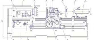
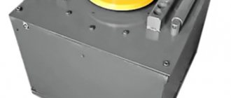
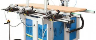
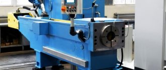
General view of the single-crank press KD2124
Photo of single crank press KD2124
Photo of single crank press KD2124
Photo of single crank press KD2124
Photo of single crank press KD2124
The meanings of the first two digits in the designation of hydraulic presses:
rice. 2. Classification and designation of hydraulic presses
- P32 - sheet metal stamping press, flanging press
- P60, P61, P63 - single-column press with correct pressing
- P31, P34 - single-column single-action press
- P33 – double-action frame press
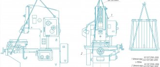
Location of the components of the single-crank press KD2124
Location of the components of the KD2124 press
List of components of the single-crank press KD2124
- Tilt mechanism - KD2324-12-001
- Drive guard - KD2324-71I-001
- Clutch-brake device - KD2324-26E-001
- Bed - KD2324-11I-001, KD2124-11I-001
- Drive - KD2324-21I-001
- Air duct - KD2324-41I-001
- Work area fencing - KD2324-73I-001
- Electrical equipment - KD2324-91E-001
- Slider balancer - KD2324-34-001
- Eccentric shaft - KD2324-23E-001
- Fencing - KD2324-72-001
- Slider - KD2324-31I-001
- Oil line - KD2324-82-001
Download files
If you want to know how relay circuits are compiled in science, download an interesting book:
• Logical techniques for compiling and analyzing relay-contact and non-contact circuits / Guidelines (manual) for practical classes in the course “Automated control systems” Direction 220300 - Automated technologies and production , pdf, 304.8 kB, downloaded: 965 times./
Splan file, in which I made the diagrams for this article:
• Press CD / Schemes in SPlan format., zip, 16.7 kB, downloaded: 1234 times./
Location of controls for single-crank press KD2124
Location of press controls KD2124
List of controls for the single-crank press KD2124
- Pedal
- Button “Slider stroke” (two-handed activation)
- Button "Stop Autowork"
- "General stop" button
- Local lighting switch
- Light signaling
- Lube Pump Button
- Light signaling
- Move counter
- Operating mode switch
- Input switch
- Control circuit lock
- Machine start button
Zero protection
I already wrote about zero protection in an article about emergency circuits in industrial equipment. The main idea is that the machine should not start rotating when the power is turned on. You must first return all the mechanisms to their original state, press the ready button, and only then can you start the engines.
For example, this principle is inherent in the zero protection of lathes - when power is applied, the engine cannot be turned on until the gearbox is brought to the neutral position.
I propose a circuit that, when power is applied, checks that the pedal is not pressed, which will be indicated by the switched on relay KA3:
Zero protection circuit
When the SB pedal is briefly pressed, relay KA3 continues to remain on in self-retaining mode, and KA1 becomes self-retaining. The EM is turned on through relay contacts KA1 and KA3. When the sensor is deactivated (end of cycle), both relays are reset. Due to inertia, the sensor becomes active again, and KA3 turns on. The circuit is ready for use again.
This scheme eliminates spontaneous activation of the press in case of problems with the pedal - getting stuck, pressing with an arbitrary object.
Kinematic diagram of the single-crank press KD2124
Kinematic diagram of the single-crank press KD2124
- Electric motor 4AC
- Drive pulley
- Drive flywheel
- Clutch-brake
- Tilt screw
- Ejector bar
- Crawler
- Adjustment screw
- Eccentric shaft
- Eccentric bushing
- screw
Operating modes of the single-crank press KD2124
Depending on the nature of the work performed and the availability of mechanization in the press control, the following operating modes are provided:
- Single move;
- Switching on with buttons (two-handed switching);
- Switching on by pedal;
- Continuous moves;
- Push;
- Manual rotation.
Single move
The “Single stroke” mode provides for the press to operate from the two-handed control buttons and from the pedal.
Continuous moves
The “Continuous strokes” mode provides only button control. The mode switch in the contactless control unit BUB-1A is set to the “Continuous strokes” position. The movable screen “Fencing of the working area” of tilting and non-tilting presses must be lowered to the lower position.
By pressing the “Start electric motor” button on the control panel, the electric motor is turned on.
By pressing the two-hand control buttons, the clutch-brake is activated. If the movable screen “Working area guard” is not lowered or has not lowered to the lowest position, then when the two-hand control buttons are pressed, the clutch-brake will not engage.
When the clutch-brake is engaged, the press slide moves automatically. The operation of the command device at the end of each stroke of the slide will not affect the operation of the electrical circuit. The clutch-brake is turned off by pressing the “Stop continuous strokes” button. In this case, the command device is activated at the end of the slider stroke.
The “Stop continuous strokes” button must be pressed until the proximity switches operate, the clutch-brake disengages and the slider stops.
The “Continuous strokes” mode is used in the presence of automation equipment , feeding blanks into the die and removing parts outside the working area, as well as when stamping from a strip with manual feed in a closed die, which excludes hands from entering the working area.
Push
The “Push” mode provides only button control. The mode switch in the BUB-1A contactless control unit is set to the “Push” position, and the second switch is set to the “Buttons” position.
By pressing the “Start electric motor” button on the control panel, the electric motor is turned on. By pressing the two-hand control buttons, the clutch-brake is turned on and off. The duration of the on state of the clutch-brake corresponds to the time of pressing the buttons, thanks to which you can stop the slider in the desired position.
The “Push” mode can only be used when setting up dies.
Manual rotation
The “Manual rotation” mode provides for the movement of the slider when the drive is rotated manually with a crowbar when the clutch-brake is engaged. When switching to this mode, you must ensure that the flywheel stops completely.
The mode switch on the control unit of the contactless BUB-1A is set to the “Manual rotation” position. In this case, the clutch-brake is activated when the electric motor is turned off,
The “Manual rotation” mode can be used when setting up presses. The slider is moved by rotating the drive manually with a crowbar installed in the flywheel hole.
Disabling the clutch-brake is done by turning the mode switch to any other position.
The method of controlling the clutch-brake, buttons or pedal is selected by a switch on the contactless control unit BUB-1A.
Push-button two-handed control
The switch is set to the “Two-handed button control” position. By pressing the two-hand control buttons on the control panel, the clutch-brake is activated for one stroke.
At the end of this stroke, the proximity switches are activated. The clutch-brake is disengaged and the slider stops at top dead center.
To carry out the subsequent movement of the slider, you must release and press both two-handed control buttons on the control panel again.
Pedal control
The switch is set to the “Pedal” position. On tilting and non-tilting presses, the Work Area Guard screen must be lowered to the down position. Pressing the pedal engages the clutch-brake. If the movable screen “Working area guard” is not lowered or has not lowered to the lowest position, then when you press the pedal, the clutch-brake will not engage. At the end of this stroke, the proximity switches are activated, the clutch-brake is released and the slider stops at top dead center. To carry out the subsequent stroke of the slider, you must release and press the pedal again.
In the “Single stroke” mode, push-button two-handed control is used when stamping from piece workpieces with manual loading and unloading.
Pedal control is used when stamping strips or large-sized workpieces from a sheet, which must be held by hand during the process of lowering the slider if there is a fixed fence for the working area on the press, as well as when stamping from piece workpieces in the presence of protective devices.
Regulation
After setting up and testing the press and during its operation, the need arises to regulate the individual components of the press.
Belts on V-belt drive pulleys must be put on manually without the use of any tools.
The tension of the belts during operation of the press must be periodically monitored and adjusted.
Types of stamping technologies
The stamping process of processing blanks can be carried out using the hot or cold method. These technological varieties involve the use of special equipment and the use of certain metal processing conditions.
Cold stamping is one of the types of stamping
The hot stamping method processes workpieces that are preheated in special devices to a given temperature. Hot stamping is necessary when there is not enough equipment power to process a cold alloy. Heating devices can be electric or plasma ovens. This method requires accurate calculation of the parameters of the finished part, taking into account the shrinkage of the metal during the cooling process.
In cold stamping, parts are formed due to the mechanical pressure of the elements of the stamping press. Cold stamping is considered a more common method of metal processing. It does not require additional equipment, complex calculations or mechanical modification of parts. Thanks to this method, the strength properties of the material increase. The resulting products are distinguished by high surface quality and precision.
This is interesting: Radial drilling machine 2M55: characteristics and documentation
Description of individual components of the crank press KD2124
Balancer
The counterbalancer is designed to eliminate the influence of the weight of the slider and the upper half of the die on the operation of the press and to prevent arbitrary lowering of the slider in emergency cases: breakage of the adjustment screw in the connecting rod or the studs of the connecting rod cover.
By design, the balancer is a single-acting pneumatic cylinder mounted on a frame.
Rod 3 (Fig. 14) is connected to the slider bracket. The compressed air into the pneumatic cylinder 2 comes from the receiver through the hole in the bottom cover 4. The piston I by the rod 3 constantly pulls the slide up.
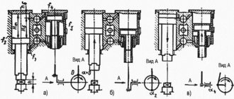
KD2124 crank press drive
KD2124 crank press drive
The press is driven from an electric motor 3 through a V-belt drive 5, a flywheel 6, and a brake clutch to the eccentric shaft.
The electric motor is installed on a swinging sub-motor plate 4. Rotation of the electric motor is counterclockwise (if you look at the end of the shaft from the flywheel side).
The belt tension is adjusted using screw 2 and nut I.
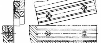
“Clutch-brake” device for single-crank press KD2124
Clutch brake single-crank press KD2124
The “Clutch-brake” device consists of a normalized “clutch-brake” unit UV3138, an air supply head 19 and a flywheel 12, the supports of which are radial ball bearings 17 mounted on a sleeve 18, which in turn is installed on an eccentric shaft 22.
Actually, the clutch-brake itself, a rigidly interlocked multi-disc friction with pneumatic activation, consists of the following parts:
- driving - driving disks 14 of the clutch with friction linings 15;
- driven - a hub with a fixedly attached piston 2, a cylinder 3 moving along the axis, support disks 8 mounted on the threads of the hub 21 and piston 2, a brake pressure disk 7 mounted rigidly on the cylinder, an intermediate clutch disk 16;
- brake - brake disc 10 with friction linings.
The “Clutch-brake” device works as follows: compressed air through the air supply head 19, the eccentric shaft 22 enters the pneumatic chamber 1 and moves the cylinder 3 along the axis of the eccentric shaft towards the clutch and clamps the drive disks 14 of the clutch, connected to the constantly rotating flywheel 12 through the fingers 13, ensuring the transmission of torque through the hub 21 to the eccentric shaft 22.
At the moment of braking of the eccentric shaft 22, compressed air from the pneumatic chamber is released into the atmosphere through the air supply head 19, the connecting sleeve and the three-way double interlocked valve.
In this case, cylinder 3, under the influence of springs 20, returns towards the brake and clamps the brake disc 10, sitting on fingers 11 connected to the frame 9. In this case, the moving parts of the press are braked.
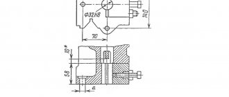
Eccentric shaft of single-crank press KD2124
Eccentric shaft of single-crank press KD2124
The eccentric shaft consists of the eccentric shaft 5 itself (Fig. 11), an eccentric bushing 6, an axle box 8 and an adapter bushing 9, intended for installing mechanization equipment on the press.
The slider stroke is adjusted by rotating the eccentric sleeve 6, which engages with the shaft 5 through an involute gear and is disengaged by rotating the nut 7.
In this case, in order to avoid displacement of the connecting rod, it is necessary to insert a wooden spacer between the connecting rod and the frame axle box.
After setting the required stroke value of the slider, the eccentric sleeve 6 is engaged with the eccentric shaft 5 and locked with screws 10, and the wooden spacer is removed.
Stopping the slider at top dead center after adjusting the slider stroke is done by rotating discs 3. Discs I and 2 are designed to control the braking distance and to count strokes. The discs are pinned together and can be rotated together after loosening the bolts 4.
Slider of single crank press KD2124
Slider of single crank press KD2124
The slider is the working body to which the upper part of the stamp is attached.
Slider 3 (Fig. 12) of the press has a box-shaped shape with prismatic double-sided guides.
The slider is attached to the eccentric shaft by means of an adjusting screw 10 and a detachable connecting rod 11, in the housing and cover of which bronze plain bearing shells are installed, covering the eccentric sleeve. An adjusting screw 10 is screwed into the connecting rod from below, the ball head of which is enclosed between the lower support 5 and the upper floating liner 6.
The ball head, support and floating liner are placed in the cup 4. After adjusting the gap in the ball joint, the nut 8 screwed into the cup is locked with a key 19. The support of the cup 4 is a shear safety washer 22, designed to be destroyed when the press is overloaded. The safety washer is installed on the wedge mechanism 2 for removing the press from the expansion. When cutting off the safety washer, it is necessary to lift the connecting rod with the adjusting screw and the sleeve by rotating the press flywheel in the “Manual crank” mode, replace the safety washer, lower the connecting rod with the adjusting screw 10 and the sleeve 4 to the original position, tighten the nut 9 and lock it with screw 20.
The size of the stamping space is adjusted by rotating the adjusting screw by its hexagon using a wrench. Before this, it is necessary to adjust the pressure in the pneumatic network using a pressure regulator within the range of 1.5...2 kgf/cm2 to ensure ease of turning the adjusting screw.
The established size of the die space is fixed by locking bushings 15 and 16, which are pulled back by screw 17.
The lower limit of die space adjustment is limited by clamp 14.
The amount of adjustment is determined by ruler 12.
At the bottom of the slide there are holes for fastening the upper die plate and a hole for the shank of the upper die plate.
The shank is fastened with clamp 23 using two studs with nuts.
The locking screw 31 serves to push away the clamp when removing the stamp. The ejector rocker arm I is located in the groove of the slider. The stops for the rocker arm are height-adjustable stops 7, mounted on the frame.
Locking bushings 15 and 16 are kept from turning by screws 18.
Pneumatic diagram of single-crank press KD2124
Design features
All units for processing metal workpieces have approximately the same structure. Three main nodes can be distinguished. These include:
- equipment engine;
- torque transmission;
- actuating mechanism.
The first nodes form the drive system, on which the functioning of the actuator depends. Each organ is responsible for a specific result. Therefore, you should understand what types of machines there are.
Main technical characteristics of the KD2124 press
| Parameter name | KD2122 | KD2124 | KD2324 |
| Main settings | |||
| Nominal press force, kN (t) | 160 | 250 | 250 |
| Maximum stroke of the slider (rod), mm | 5..55 | 5..65 | 5..65 |
| Table dimensions, mm | 280 x 420 | 340 x 500 | 340 x 500 |
| Dimensions of the hole in the table, mm | 140 x 210 | 170 x 250 | 170 x 250 |
| Diameter of hole in table, mm | 180 | 210 | 210 |
| The greatest distance between the table and the slider in its lower position is the closed height of the press, mm | 220 | 250 | 250 |
| Distance from the rod axis to the frame (reach), mm | 160 | 190 | 190 |
| Frequency of slider strokes, 1/min | 120 | 160 | 160 |
| Frequency of slider strokes single from the button, 1/min | 55 | 50 | 50 |
| The amount of adjustment of the distance between the table and the slide, mm | 45 | 55 | 55 |
| Clear distance between bed posts, mm | 200 | 240 | 240 |
| Thickness of the die plate, mm | 40 | 75 | 75 |
| Dimensions of the bottom surface of the slide, mm | 190 x 220 | 225 x 280 | 225 x 280 |
| Maximum stroke of the ejector in the slide, mm | 40 | 30 | 30 |
| Table height above floor level, mm | 760 | 820 | 820 |
| Brake clutch type | UA3135 | UA3138 | |
| Electrical equipment | |||
| Number of electric motors | 1 | 1 | 1 |
| Main drive electric motor, kW | 2,0 | 2,7 | 2,7 |
| Dimensions and weight of the press | |||
| Press dimensions (length width height), mm | 990 x 1085 x 1875 | 1170 x 1191 x 2110 | 1180 x 1600 x 2295 |
| Press weight, kg | 1325 | 2100 | 1975 |
- Banquetov A.N., Bocharov Yu.A., Dobrinsky N.S. and others. Press-forging equipment, 1970
- Bocharov Yu.A., Prokofiev V, N. Hydraulic drive of forging and pressing machines, 1969
- Belov A.F., Rozanov B.V., Linz V.P. Volumetric stamping on hydraulic presses, 1971
- Zhivov L.I. Forging and stamping equipment, 2006
- Kuzmintsev V.N. Forging with hammers and presses, 1979
- Rozanov B.V. Hydraulic presses, 1959
- Titov Yu.A. Equipment for forging and pressing shops, 2001
- Shcheglov V.F. Forging and pressing machines, 1989
- Berlet Development of forging drawings, 2001
- Rudman L.I. Sheet Forming Equipment Handbook, 1989
- Romanovsky V.P. Handbook of Cold Forging, 1965
- Okhrimenko Ya.M. Technology of forging and stamping production, 1966
- Kuzmintsev V.N. Forging with hammers and presses, 1979
- Meshcherin V.T. Sheet stamping. Atlas of circuits, 1975
Bibliography:
Related Links. Additional Information
- Manufacturers of forging and pressing equipment in Russia
- Classification and designation of hydraulic and crank presses
- Mechanical presses
- Hydraulic presses
- Automatic forging and pressing machines
- Bending and straightening machines
- Guillotine shears, press shears
- Hammers
- Repair of hydraulic systems of metal-cutting machines
- Designations of hydraulic circuits of metal-cutting machines
- Repair of gear hydraulic pumps
Home About the company News Articles Price list Contacts Reference information Interesting video KPO woodworking machines Manufacturers
Classification and designation of pressing equipment
An example of the designation of the most commonly used presses:
KV2132 - single-crank open press (C-type), simple-action, two-post with a fixed table and a nominal force of 1600 kN
Where:
- K - type of press (K, P, I, and A) - crank press (mechanical)
- B - modification of the press
- 21 - type of pressing equipment according to classification (see Fig. 1)
- 32 - value of the main parameter - nominal press force (see table 1) - nominal press force 1600 kN
P6324B - single-column hydraulic press, properly pressed in, with a nominal force of 250 kN
Where:
- P - type of press (K, P, I, and A) - hydraulic press
- 63 - a type of pressing equipment according to classification (see Fig. 2)
- 24 - value of the main parameter - nominal press force (see table 1) - nominal press force 250 kN
- B - modification of the press
Ladder logic
As I already said, any circuit on a relay corresponds to a circuit on logical elements. AND, OR, NOT, Delay Line, Trigger (memory cell) - all this is implemented on a relay.
Here is an interesting video that talks about this in detail:
I recommend the site pro-rza.ru for those who work with relay circuits (as well as program algorithms) professionally, and not just based on intuition). You can also find a lot of interesting information on the topic if you enter the query “relay logic circuits” in Yandex.