Car tachometer
is a measuring device that is designed to measure the number of revolutions of the engine crankshaft per minute (rpm). Previously, mechanical tachometers were installed in cars. Modern cars have electric or electronic tachometers.
While the car engine is running, the tachometer allows you to monitor the stability of its speed at idle and while the car is moving. The stability of idle speed can be used to judge the condition of the fuel supply system, ignition system and the engine itself.
When setting the idle speed and adjusting the engine ignition timing using a strobe light, you cannot do without a tachometer. It is necessary to simultaneously make adjustments and monitor engine speed. After each tightening of the adjustment screw, it is inconvenient to look at the readings of the tachometer installed inside the car. A mirror installed in the cabin can help out, but this is also not the best solution. It is much more convenient to have a tachometer built into a strobe light.
When making a strobe light with my own hands, I mounted a tachometer into its body. When checking and adjusting the engine's OZ, this technical solution showed ease of use.
Analog tachometer circuits published on the Internet are distinguished by a greater error in readings; not every car enthusiast can replicate them made on digital microcircuits.
The tachometer circuit design we bring to your attention is distinguished by its simplicity and high accuracy of readings, regardless of changes in ambient temperature and supply voltage. It has an extended scale, which allows, when using a small-sized dial indicator, to measure the engine speed with high accuracy.
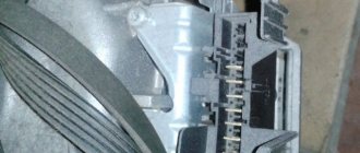
Installation of a remote tachometer
The main purpose of the tachometer is that it informs the driver about the frequency at which the crankshaft of the car engine rotates.
It is worth understanding that the speedometer and tachometer show different things and perform different functions. It is impossible to accurately determine the speed of a car using a tachometer, and it is impossible to monitor the increase in crankshaft revolutions using a speedometer. Most often, drivers use the tachometer to select when to change gear. Doing this using the tachometer is very convenient - you just need to pay attention to when the arrow approaches the border and change gear.
Remote tachometer
Very often, drivers get lost when they get into a car that does not have a tachometer. By the way, this is not necessarily typical only for old cars, such as the VAZ-2101 or GAZ-53, but the new Daewoo Lanos in the basic version or the VAZ 2108 also do not have a tachometer. An experienced driver can easily do without a tachometer, but for those who are used to it, they will either have to get used to it, or start looking for a remote tachometer.
Self-production
The remote tachometer is needed for the same thing as the one integrated into the panel - to display the crankshaft speed. It can be made for both four-stroke and two-stroke engines. The latter is relevant for old mopeds or motorcycles. There are two ways to get yourself a remote tachometer:
Any of the selected options is beneficial, however, there is still a difference. This difference is in price and time spent. Of course, if you buy a ready-made one, you will spend more money, but it will simply be connected.
Having done it yourself, you can be confident in its performance and the accuracy of its readings. The fact is that very cheap remote tachometers, as a rule, lie very much. But more expensive ones are not affordable for everyone. It is in this case that it will be convenient to make a homemade tachometer.
Manufacturing process
As we already understood, it happens that the tachometer is simply missing. In this case, you will have to do your own production. You can find a lot of instructions on the Internet, but we have developed the most optimal one and described in detail how to do everything correctly and accurately.
So, let's start by collecting the necessary tools and parts. We will need:
First we need to fit the housing tightly to the engine tachometer mechanism so that there are no backlashes. If the mechanism is deeply recessed into the body, then you will have to cut off all the excess with scissors to make it look beautiful. It will be necessary to cut so that there are no jagged edges or sharp edges. If a sharp edge accidentally comes out, you will have to grind it to a smooth surface.
Now we fill the inner cavity of the body of the future engine tachometer and the outer surface in the place where it will be attached to the panel with polyurethane foam. After the foam has dried, you can use a knife to give the body any beautiful shape. Inside, you need to make the space so that the mechanism sits tightly and does not move. You also need to remember about the holes for the wires. Try the case on the panel in advance and think about how the wires will be laid and where it will be more convenient to make these same holes.
Now let's move on to external work. Using sandpaper, sand all surfaces until they are perfectly smooth. Now we need to make sure that the housing of the future engine tachometer is strong enough.
To do this, we cover it with fiberglass and fill it all with epoxy glue. The glue must be allowed to dry for at least a day; further work cannot be started yet - the workpiece may be damaged. Now you need to putty the engine tachometer blank. You need to devote maximum time to this stage, since painting will come next and the workpiece should be as even and smooth as possible so that everything looks decent. In principle, you can paint it any color, but preferably the color of the car panel on which the engine tachometer will be located.
If the tachometer for a two-stroke motorcycle will always be on the street, then the paint will have to be chosen as resistant as possible so that it can withstand all possible weather changes and the characteristics of the motorcycle’s operation. That's it, now you need to place the mechanism inside the case, remove the wires and connect them to the machine. After checking, if everything is fine, then glue the body to the selected location on the panel.
DIY digital tachometer on AVR ATtiny2313, KR514ID2 and optocoupler
DIY digital tachometer on AVR ATtiny2313, KR514ID2 and optocoupler
Good afternoon. I present for your consideration a diagram of a simple digital tachometer on an AVR ATtiny2313
,
KR514ID2
, and an optocoupler designed by me.
Let me make a reservation right away: there are many similar schemes on the Internet. Each implementation has its own pros and cons. Perhaps my option will be more suitable for someone. I'll probably start with those. tasks. Task
: you need to make a digital tachometer to control the speed of the electric motor of the machine.
Introductory conditions
: There is a ready-made reference disk with 20 holes from a laser printer.
There are many optocouplers available from broken printers. Average (working) speeds are 4,000-5,000 rpm. The error of the displayed results should not exceed ± 100 revolutions. Limitation
: the power supply for the control unit is 36V (the tachometer will be installed in the same housing with the control unit - more on this below).
A small lyrical digression.
This is my friend's machine. The machine is equipped with a PIK-8 electric motor, the speed of which is controlled according to a modified diagram found on the Internet. At the request of a friend, a simple tachometer for the machine was developed.
Initially, it was planned to use ATMega16 in the circuit, but after considering the conditions, it was decided to limit ourselves to ATtiny2313, operating from an internal (RC) oscillator at a frequency of 4 MHz.
General scheme
as follows:
As you can see, nothing complicated. To convert binary code into seven-segment, I used the KR514ID2 decoder, this gives three advantages at once.
- Firstly, it saves space in the ATtiny2313 memory by reducing the working code (since the procedure for software conversion of binary code to seven-segment is not included in the firmware as it is unnecessary).
- Secondly: reducing the load on the ATtiny2313 outputs, because the LEDs are “illuminated” by KR514ID2 (when the number 8 is displayed, the maximum consumption will be 20-30 mA (typical for one LED) * 7 = 140-210 mA, which is “a lot” for the ATtini2313 with its full nameplate maximum (loaded) consumption of 200 mA).
- Thirdly, the number of “busy” legs of the microcontroller has been reduced, which gives us the opportunity in the future (if necessary) to upgrade the circuit by adding new capabilities.
Assembling the device
implemented on a breadboard.
To do this, a circuit board from a non-working microwave oven lying in the bins was disassembled. The digital LED indicator, key transistors (VT1-VT4) and limiting resistors (R1 - R12) were taken as a kit and transferred to the new board. The entire device is assembled, if the necessary components are available, with smoke breaks in half an hour. Please note:
the KR514ID2 microcircuit has a positive power supply pin of 14 and a minus pin of 6 (marked in the diagram). Instead of KR514ID2, you can use any other binary code decoder into a seven-segment one powered by 5V. I took what was at hand. The “h” and “i” pins of the digital LED indicator are responsible for two points in the center between the numbers; they are not connected as unnecessary. After assembly and firmware, provided there are no installation errors, the device starts working immediately after switching on and does not require configuration.
If it is necessary to make changes to the tachometer firmware, an ISP connector is provided on the board.
In the diagram, pull-up resistor R12, rated 30 kOhm, was selected experimentally for a specific optocoupler. As practice shows, it may differ for different optocouplers, but the average value of 30 kOhm should ensure stable operation for most printer optocouplers. According to the ATtiny2313 documentation, the value of the internal pull-up resistor ranges from 20 to 50 kOhm, depending on the implementation of a specific batch of microcontrollers (page 177 of the ATtiny2313 passport), which is not entirely suitable. If anyone wants to repeat the circuit, they can first turn on the internal pull-up resistor, perhaps it will work for you, for your optocoupler and your MK. It didn't work for me for my set.
This is what a typical optocoupler from a printer looks like.
The optocoupler LED is powered through a 1K limiting resistor, which I placed directly on the board with the optocoupler. To filter voltage ripples, there are two capacitors in the circuit, an electrolytic one of 220 µF x 25V (which was on hand) and a ceramic one of 0.1 µF (the general circuit for connecting the microcontroller is taken from the ATtiny2313 data sheet).
To protect it from dust and dirt, the tachometer board is coated with a thick layer of automotive varnish.
Replacement of components.
You can use any four-digit LED indicator, either two double or four single. At worst, assemble the indicator on separate LEDs.
Instead of KR514ID2, you can use KR514ID1 (which contains current-limiting resistors inside), or 564ID5, K155PP5, K155ID9 (when the legs of one segment are connected in parallel), or any other binary to seven-segment converter (with appropriate changes in the connection of the microcircuit pins).
Provided the installation is correctly transferred to the ATMega8/ATMega16 MK, this firmware will work as on the ATtiny2313, but you need to correct the code (change the names of the constants) and recompile. Comparisons have not been made for other AVR MCUs.
Transistors VT1-VT4 - any low-current ones, operating in switch mode.
Principle of operation
is based on counting the number of pulses received from an optocoupler in one second and recalculating them to display the number of revolutions per minute. For this purpose, an internal counter Timer/Counter1 is used, operating in the mode of counting pulses arriving at input T1 (pin PD5 pin 9 MK). To ensure stable operation, software debounce mode is enabled. Seconds are counted by Timer/Counter0 plus one variable.
Calculation of revolutions
, which I would like to dwell on, occurs according to the following formula: M = (N / 20) *60, where M is the calculated revolutions per minute (60 seconds), N is the number of pulses from the optocoupler per second, 20 is the number of holes in the reference disk. In total, simplifying the formula we get: M = N*3. But! The ATtiny2313 microcontroller does not have a hardware multiplication function. Therefore, summation with offset was applied. For those who do not know the essence of the method: The number 3 can be expanded as 3 = 2+1 = 21 + 20. If we take our number N, shift it to the left by 1 byte and add another N shifted to the left by 0 byte - we get our number N multiplied by 3. In the firmware, the code on the AVR ASM for a two-byte multiplication operation looks like this:
Mul2bytes3: CLR LoCalcByte //clear the working registers CLR HiCalcByte mov LoCalcByte,LoInByte //load the values received from Timer/Counter1 mov HiCalcByte,HiInByte CLC //clear the carry bit ROL LoCalcByte //shift through the carry bit ROL HiCalcByte CLC ADD LoCalcByte,LoIn Byte/ / sum taking into account the carry bit ADC HiCalcByte,HiInByte ret
Functionality check and accuracy measurement
was carried out as follows. A cardboard disk with twenty holes was glued to the computer cooler fan. The cooler speed was monitored through the motherboard BIOS and compared with the tachometer readings. The deviation was about 20 revolutions at a frequency of 3200 revolutions/minute, which is 0.6%.
It is quite possible that the real discrepancy is less than 20 revolutions, because Motherboard measurements are rounded within 5 turns (based on personal observations for one specific board). The upper limit of measurement is 9,999 rpm. The lower limit of measurement, theoretically from ±10 revolutions, but was not measured in practice (one pulse from an optocoupler per second gives 3 revolutions per minute, which, taking into account the error, should theoretically correctly measure speeds from 4 revolutions per minute and above, but in practice this the indicator must be at least doubled).
I will separately dwell on the issue of nutrition.
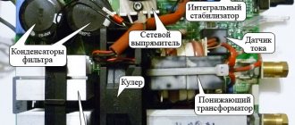
The entire circuit is powered from a 5V source, the estimated consumption of the entire device does not exceed 300 mA. But, according to the terms of the technical specifications, the tachometer must be structurally located inside the engine speed control unit, and a constant voltage of 36V is supplied to the unit from LATR. In order not to pull a separate power wire, an LM317 is installed inside the unit in the nameplate mode, in the mode of reducing the power to 5V (with limiting resistor and zener diode to protect against accidental overvoltage). It would be more logical to use a PWM controller in step-down converter mode, like the MC34063, but in our city it’s problematic to buy such things, so we used what we could find.
Photos
tachometer boards and the finished device.
More photos
After the layout of the boards and the first test assembly, the box with the device went for painting.
Source,
on AVR ASM, AVR Studio4 project files and compiled .HEX file are located here: https://djkiridza.org.ua/ldd/taho-v029.zip. Mirror here: https://fileobmen.org.ua/DJ_Kiridza/taho-v029.zip
If your tachometer does not work
immediately after switching on, with known correct installation:
1) Check the operation of the microcontroller, make sure that it is powered by an internal generator. If the circuit is assembled correctly, four zeros should be displayed on the dial.
2) Check the level of pulses from the optocoupler, if necessary, select the value of resistor R12 or replace the optocoupler connection circuit. It is possible to reverse connect the optotransistor with a pull-up to minus, with the internal pull-up resistor MK turned on or not. It is also possible to use the transistor in the switching (inverting) mode of operation.
PS
at the request of the customer, the tachometer displays not one zero, but four in the absence of pulses from the optocoupler.
P.P.S.
The tachometer turned out to be very sensitive to changes in engine speed. Minor voltage ripples cause a deviation in the rotation speed, which is immediately displayed on the tachometer screen. In the future, I plan to make processing to round the displayed results within ±50 revolutions, if the customer needs it.
Connecting a finished tachometer
If you have chosen the option of purchasing a ready-made device for measuring engine crankshaft speed, then all that remains is to connect it correctly to the car. As already mentioned, the tachometer is relevant for cars without this device. As a rule, these are quite old gasoline engines with a gasoline engine, the connections to which are quite simple to understand.
It is quite easy to understand the wires - they all have a characteristic insulation of a certain color, so you can only make a mistake if you do not connect carefully. The connection diagram for the remote engine tachometer itself is very simple.
First, we find the negative wire (usually it has black insulation) and “throw” it onto the machine ground (screw it to the body with a bolt). Now we connect the “plus” (usually red) to the power terminal of the ignition switch. The last wire that is connected directly to the measuring device. It needs to be connected to the ignition coil terminal, which is connected to the distributor breaker. If the car is equipped with a contactless ignition system, then the difference in connection is only that you will have to connect not to the ignition coil, but to the switch. That's all, as we see, there is nothing complicated either in connecting it yourself or in making a tachometer, any person can do all this.
Tachometer for motorcycles
How to install an electronic tachometer on a motorcycle? Here, motor vehicle owners have a choice: either purchase ready-made equipment or make it themselves. Let's assume that there is a motorcycle, there is a device for monitoring revolutions. But how to connect an electronic tachometer? For these purposes, the TX-193 device from the six is best suited for installation on domestic brands of motorcycles.
If the motorcycle is not domestic and there is still the same electronic tachometer, the connection diagram will change slightly. In this case, power will have to be supplied through the ignition switch. There are special contacts there for these purposes. If the motorcycle does not have a starter, then the battery should be connected to the output of the rectifier. And from the battery you can supply power directly to the tachometer through a switch. If you don't have a rectifier, you need to buy one. If you don't have a battery, you can install one. The simplest option is a power source from a UPS or an old flashlight. If you connect the measuring device directly to the generator coil, then it will burn out. To avoid this, you can ask your neighbor, a radio amateur, to make a voltage regulator using thyristors.
If the engine has three cylinders, then signals from two coils are input here. There are also technical possibilities for installing a tachometer on six-cylinder motorcycles, but for this you already need to purchase branded equipment.
Homemade tachometer for a car
Some car enthusiasts get so used to the tachometer that when replacing a car that does not have a tachometer, they feel very uncomfortable. The tachometer helps to properly adjust the engine, reduce gasoline consumption, increase the overall engine life and learn to drive a car correctly. There are ready-made tachometers available for purchase, but the price is usually quite high. There are complex and simple diagrams of car tachometers, according to which you can make a tachometer yourself. I offer simple tachometer diagrams .
The first version of a simple tachometer.
To measure the number of revolutions, chopper pulses or voltage from a spark plug are used, since their frequency is linearly related to the speed of the car engine shaft. It is also possible to provide inductive coupling with this circuit, which is done in the device, the circuit of which is shown in the figure.
The basis of the circuit of this tachometer is a single-vibrator (DA1), which is triggered by pulses from the operating ignition system of the car, induced in coil L1. Input terminal X1 can be used to adjust the tachometer or to supply a signal from the breaker, as shown in the dotted line. For a four-cylinder 4-stroke engine with 3000 rpm, the interruption frequency will be 100 Hz, and for 1500 rpm - 50 Hz, which allows you to simply calibrate the device to the mains frequency.
Pulses from output 3 of the DA1 microcircuit are sent to a dial indicator - milliammeter RA1, which integrates them and shows the current voltage in the circuit. Since the duration of all pulses at the output of the monovibrator is the same, the voltage that the device will show will be proportional to the frequency of spark formation. The PA1 scale can be calibrated in shaft speed (revolutions per minute). As a sensor (coil L1), you can use a magnetic head from a tape recorder, located close to the high-voltage coil, or you will need to wind it on the wire running from the ignition coil to the distributor (reinforced with insulating tape). To protect the input of the microcircuit from high-voltage surges, it is better to use a TVS diode with a limiting voltage of 12 V as VD2. You can also use a tape signal level indicator or any similar device as an indicator.
The following is a diagram of a simple car tachometer. To make a tachometer, you will again need a large recording level indicator from a tape recorder (M476Z). Note that this circuit is very simple, it’s like a rectifier-integrator of pulses that come from the car’s ignition system breaker. Please note that the highest mark on the scale is 6000 rpm.
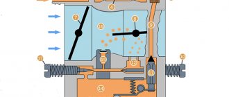
Another simple diagram of a car tachometer. The device is designed to measure the crankshaft rotation speed of carburetor engines with an electrical system in which the minus of the battery is connected to the housing.
And finally, another simple tachometer diagram for a motorcycle or moped . The tachometer is designed to work with a single-cylinder two-stroke internal combustion engine with a contact or contactless ignition system and allows you to measure the crankshaft speed up to 10,000 rpm. Tachometer circuit
Operating principle of the device. In the initial state, transistor VT1 is closed and VT2 is open. At this time, the left (according to the diagram) plate of capacitor C 5 is connected through a small resistance of the open transistor VT2 to the +5 V bus. At this time, no current flows through the microammeter PA1. At the first negative half-cycle of alternating voltage applied to the tachometer input, transistor VT1 opens and VT2 closes. At this time, C5 is quickly charged through the microammeter PA1, VD3 and R5. With a positive half-cycle of the input voltage, VT1 closes and VT2 opens. Now C5 is discharged through the low resistance of open VT2 and VD4. At the next negative half-cycle, the process is repeated in a similar way. Trimmer resistor R6 sets the upper limit of the frequency of the measured signal. The value of capacitor C5 is selected depending on the type of engine. The higher the engine speed, the smaller the capacitance of capacitor C5 should be. A correctly assembled tachometer circuit does not require adjustment. You just need to use trimming resistor R6 to set the maximum tachometer readings by opening the engine throttle all the way.
Connection diagram of the tachometer to the electrical equipment of a motorcycle or moped.
Source
Microelectric Voltage Generated Machine
The tachometer generator converts the shaft rotation indicator into an electrical signal. Its operation uses the properties of the angular velocity of the rotor, the excitation flow, which is proportional to the generated EMF. Most modern tachogenerators are the permanent magnet type. These devices use a rotating joint, one end of which is connected to the machine shaft, inducing an electromotive force (voltage) proportional to the speed of the shaft. The armature contacts are connected to the voltmeter circuit, converting the voltage into a speed value.
These tachometers are distinguished by their accuracy, maximum permissible performance and operating temperature. Used as sensors in various automotive and electromechanical computer devices. Operate in AC or DC networks.
Master class on making a digital and analog homemade tachometer
A tachometer is a device designed to measure engine speed while driving and display this information to the driver. The received data is shown to the motorist on the dashboard or, if the device was installed additionally, on the corresponding screen in the cabin. This material will allow you to learn how to build a tachometer at home with your own hands.
Homemade microcontroller device
To make a homemade tachometer on a microcontroller for your car to measure engine speed, you will need the following spare parts:
In this case, an optical regulator will be used instead of a slot regulator. Thanks to this, you do not have to worry about the thickness of the rotor; the number of blades will not change the readings. In addition, the optical controller allows you to read the drum revolutions, unlike a slotted one.
To begin the task, prepare all the elements and you can begin:
Schematic parts list
- Microcircuit - Arduino
- Resistors – 33k, 270 ohm, 10k potentiometer
- LED element - blue
- IR LED and Photodiode
- 16 x 2 LCD screen
- 74HC595 shift register
Here, instead of a slot sensor, an optical one is used - reflection of the beam. This way they don't have to worry about the thickness of the rotor, the number of blades won't change the reading, and it can read the drum revolutions - which the slot sensor cannot.
So first of all you will need an IR emitting LED and a photodiode for the sensor. How to assemble it is shown in step-by-step instructions. Click on the photo to enlarge the size.
- 1. First you need to sand the LED and photodiode to make them flat.
- 2. Then fold the strip of paper sheet as shown in the picture. Make two such structures so that the LED and photodiode fit tightly into it. Connect them together with glue and paint them black.
- 3. Insert LED and photodiode.
- 4. Glue them together with superglue and solder the wires.
Resistor values may vary depending on which photodiode you are using. The potentiometer helps to reduce or increase the sensitivity of the sensor. Solder the sensor wires as shown in the figure.
The tachometer circuit uses a 74HC595 8-bit shift register with a 16x2 LCD display. Make a small hole in the housing to fix the LED indicator.
Solder a 270 ohm resistor onto the LED and insert it into pin 12 of the Arduino. The sensor is inserted into a cubic tube to give additional mechanical strength.
That's it, the device is ready for calibration and programming. You can download the program from this link.
A simple device based on a microcalculator
There is another option for making an electronic digital tachometer for a gasoline or electric engine; in this case, a microcalculator will be used as the basis. This option will be especially relevant for those who have problems with the element base. It should be noted that ultimately the device will not be able to provide 100% accurate readings, and such a device will not show the number of revolutions per minute on the screen. However, the microcalculator itself is an excellent device for counting signals.
Inductive controllers and others can be used as a signal regulator. When the disk rotates, one signal should be shown on the display per revolution. In this case, the controller contacts must be open, and at the moment when the unit passes the disk tooth, these contacts must close. In general, it is optimal to use such a do-it-yourself tachometer in cases where measurements will not be taken frequently. If you want to install regular speed monitoring in your car, then, of course, it is better to use more reliable devices (the author of the video is Alexander Novoselov).
Exploitation
The simplest tachometer, made with your own hands on the basis of a calculator, works after soldering the contacts to the addition button of the computer.
Measuring the rotation speed is performed as follows:
- The micro calculator turns on.
- The “+” and “1” keys are activated synchronously.
- The gadget starts up and measurements are taken on it. To ensure accurate readings, the stopwatch should be turned on at the same time as the calculator.
- Wait 30 seconds and then look at the screen. The corresponding value should appear on it.
- This indicator is the number of revolutions in 30 seconds. Multiplying the number by two, we get the number of rotations per minute.
Analog and digital tachometers
An analog tachometer for a diesel or gasoline engine is designed to convert an electronic pulse and output it to an indication device. As for digital devices, they convert an analog pulse into a certain sequence of ones and zeros, which, in turn, are recognized by controllers (video author - Alexander Jung).
Analog options consist of the following components:
As for digital devices, their purpose is the same, but the design of a digital gadget is based on other components:
The principle of operation of the tachometer is quite simple
There are several types of design:
Pulse electrical circuit
A mark emitting any field is installed on the shaft whose frequency is being measured.
Most often this is a small magnet. A reading device – a sensor – is placed next to the shaft. Pulses corresponding to the shaft rotation speed are formed on it.
An electronic circuit receives signals and outputs them to a display device. Instead of a magnet-sensor pair, a photo and an LED are sometimes used.
Then a disk with a hole is installed on the shaft, and reading occurs using flashes of light.
The advantage of the scheme is perfect accuracy. In fact, this is a digital device that works without errors. In addition, this scheme does not take power away from the engine.
Disadvantage: Requires power supply. This excludes the use of the device in purely mechanical units.
Car tachometer - how it works
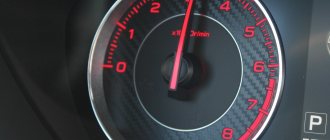
A tachometer is a special device used to determine the speed of a vehicle engine and all its rotating components. Its main task is to prolong the normal functioning of the engine by selecting the correct gear. When the driver sees that the needle of such an analog device, which is included in the basic equipment of any car, is near the red zone, he knows that it is necessary to immediately change gear.
Whatever car tachometer you choose (digital or a simpler dial), the principle of its operation remains the same. It is as follows: the device counts (in reverse, forward or in both directions) the number of pulses recorded by the sensors. In addition, the device takes into account the order of arrival of recorded pulses and pauses separating them from each other.
Subsequently, he analyzes the received data and converts them into values understandable to the driver, expressed in meters and minutes. Electronic car tachometers are currently considered the most accurate, the measurement error of which does not exceed 100 rpm. Most such devices can have an error of up to 500 revolutions.
How the counter works
The remote mini frequency meter/tachometer/pulse counter is very simple and takes into account what the phototransistor sees after being reflected from an object illuminated by an infrared emitting LED (the IR diode is only activated at the moment of counting). You can make the circuit almost entirely on a microcontroller without using an op-amp, but it was decided to use an op-amp to increase the sensitivity of the device. The base is a modified and simplified version of the heart rate monitoring unit.
In mode “1”, it is enough to bring the front part of the counter to the tested area and wait for the signal to stabilize. The measurement lasts 0.5 s, and if it is identical in at least two consecutive measurements, then the program displays the result by cycling the digits on the display separating each digit with a short blanking.
Due to the simplification of the operation and reduction of measurement time, the result always becomes even - the program multiplies it by 2, which will allow the result to be calculated “per second”. Despite this rounding, the results are surprisingly accurate and the possible measurement error is relatively small. In practice, the frequency was measured in the range of up to 40 kHz, and it copes with this without problems.
As soon as we read the result and want to measure something, briefly press the button and measure again. But when we hold the button, we exit the current mode and switch to another.
In pulse counting mode “2”, measurement begins immediately after confirming the mode (short press of the button). A second press stops the measurement and displays the result. Reset is a second press that starts the next counting cycle. At this point, you can hold the button longer and return to mode selection mode.
Digital and analogue tachometers
All modern devices that help a motorist switch to the desired gear in time are divided into two types:
Among domestic car enthusiasts, analog devices are very popular, including:
The device with the indicated elements is a regular electronic car tachometer, its connection is very simple. At the same time, it clearly performs its function, signaling the person behind the wheel that a gear change is required.
The digital tachometer consists of the following parts:
You can easily replace an analog car tachometer with a more modern device; tuning the device will allow you to perform high-quality adjustments of the car engine ignition units, as well as set the economizer thresholds as accurately as possible.
Standard and remote car tachometer
Based on the installation method, the devices we describe are divided into standard and remote. The first ones are mounted directly into the dashboard of the car. This is the option that is currently common. The remote installation assumes that the tachometer is located on the dashboard. This method of installing the device is now also gaining many fans who are trying to give their car a more elegant and attractive appearance.
Let us add that it is not difficult to install a car tachometer with your own hands, choosing the remote model you like. On the Internet you can find original diagrams for connecting devices that guarantee sufficiently high accuracy of measurements and at the same time their operation does not depend on changes in the supply voltage and the temperature of the air surrounding the vehicle.
Source
DIY car tachometer
Car tachometer
is a measuring device that is designed to measure the number of revolutions of the engine crankshaft per minute (rpm). Previously, mechanical tachometers were installed in cars. Modern cars have electric or electronic tachometers.
While the car engine is running, the tachometer allows you to monitor the stability of its speed at idle and while the car is moving. The stability of idle speed can be used to judge the condition of the fuel supply system, ignition system and the engine itself.
When setting the idle speed and adjusting the engine ignition timing using a strobe light, you cannot do without a tachometer. It is necessary to simultaneously make adjustments and monitor engine speed. After each tightening of the adjustment screw, it is inconvenient to look at the readings of the tachometer installed inside the car. A mirror installed in the cabin can help out, but this is also not the best solution. It is much more convenient to have a tachometer built into a strobe light.
When making a strobe light with my own hands, I mounted a tachometer into its body. When checking and adjusting the engine's OZ, this technical solution showed ease of use.
Analog tachometer circuits published on the Internet are distinguished by a greater error in readings; not every car enthusiast can replicate them made on digital microcircuits.
The tachometer circuit design we bring to your attention is distinguished by its simplicity and high accuracy of readings, regardless of changes in ambient temperature and supply voltage. It has an extended scale, which allows, when using a small-sized dial indicator, to measure the engine speed with high accuracy.
Homemade car electronic tachometer
An electronic tachometer is a digital device made of electronic components and used to measure the speed of an electric motor or any other rotating object in revolutions per minute. It is located in the car dashboard and has good visibility and measurement accuracy.
Simple speed metronome
Tachometer comes from two Greek words: “tacho” meaning “speed” and “metronome” meaning “to measure”. It works on the principle of a generator and determines the voltage corresponding to the speed of the shaft. It is also known as a revolution counter. Principle of operation:
- induction;
- electromagnetic;
- electronic;
- optic.
Historically, the first mechanical tachometer was developed based on the measurement of centrifugal force. In 1817 they were used to measure the speed of traction machines, but after 1840 they were used primarily to measure the speed of vehicles. A digital tachometer is an optical sensor designed to determine the angular velocity of a rotating element. Areas of use:
Read also: How to make a cat sleep at night
- Cars, planes, tractors, trains, light rail vehicles and their repair.
- Laser tools.
- Medical use. A hematachometer is a device placed in an artery or vein that measures the speed of blood movement through a rotating turbine. The indications are used to diagnose circulatory problems such as thrombophlebitis.
- Analog audio recording that measures the speed of an audio tape.
- Estimation of traffic speed and volume.
An important parameter that is taken into account when choosing a device is the operating speed range. It sets the limit of the measurement that the device is capable of monitoring. Another parameter is accuracy, which is specified in units such as ± RPM. Sensor technology used: contact, photoelectric, inductive and Hall effect.
In a contact type device, it comes into contact with a rotating part. A photoelectric device uses light rays, either visible or infrared, to measure speed. The frequency of the break, which is used to calculate speed. Inductive instruments use magnetic elements to induce magnetic fields and an activation frequency to measure speed. Design features:
Display configurations include analog visual indicators, digital or graphic video displays. User interfaces and control types include analog front or digital panels and computer programmable interfaces. Modern tachometers are equipped with software for running on a PC. Many have network or communication interfaces. Available electrical outputs:
- analog voltage;
- analog current;
- analog modulated frequency;
- switch or alarm;
- LED screen.
Tachometers are classified based on data acquisition technology. Types of devices used:
- Analog . Consists of a meter and a dialing interface. They do not have the ability to store a database, and also do not calculate average readings and their deviations. The driving speed is converted into voltage using an external frequency converter. This measurement is then displayed by an analog voltmeter.
- Digital - consist of an LCD display or LED indicator and memory for storing information. They carry out statistical operations and are suitable for precise measurement and monitoring of all types of time. Digital tachometers are more common these days, giving numerical readings instead of using dials.
- Contact type, in contact with the rotating shaft, attached to a diesel engine or electric motor. For example, an optical encoder or magnetic sensor measures revolutions. They are capable of measuring rotation speed in the range from 0.5 rpm to 10 thousand rpm, have an LCD display, and work with an operating temperature range from 0 to + 40 C.
- The non-contact type does not require physical contact with the rotating element. In this type, a laser or optical disk is connected to a shaft and the result is read by an infrared beam or laser. This type measures speeds from 1 to 99.999 rpm (lathe), the measuring angle is less than 120 degrees. Equipped with an LCD display, they are efficient, durable, accurate and compact, and can be seen from a long distance.
- Temporal , which calculates the speed from the interval between incoming pulses. The resolution of this tachometer is not limited, so it is more accurate in low speed measurements.
- Frequency , which calculates the speed from the frequency of the pulses. This type works using a red LED and its rotation depends on the rotating element. It is used for high speed measurements. An inexpensive and highly effective Chinese version is sold on the market.
Microelectric Voltage Generated Machine
The tachometer generator converts the shaft rotation indicator into an electrical signal. Its operation uses the properties of the angular velocity of the rotor, the excitation flow, which is proportional to the generated EMF. Most modern tachogenerators are the permanent magnet type. These devices use a rotating joint, one end of which is connected to the machine shaft, inducing an electromotive force (voltage) proportional to the speed of the shaft. The armature contacts are connected to the voltmeter circuit, converting the voltage into a speed value.
These tachometers are distinguished by their accuracy, maximum permissible performance and operating temperature. Used as sensors in various automotive and electromechanical computer devices. Operate in AC or DC networks.
Operating principle of a car meter
The tachometer is used to check the performance of the engine and helps the auto mechanic understand its condition to optimize operation within acceptable parameters. The operating principle of a car electronic tachometer is simple. The ignition system triggers a voltage pulse in the electromechanical part of the tachometer, which responds to the average voltage of the pulses in proportion to the engine speed. The signal is transmitted by a double shielded cable to the indicator. Tachometers are temperature compensated to process measurements in the range of -20 to + 70 C ambient.
It allows the driver to select appropriate throttle and gear settings while driving, as long-term use at high speeds causes insufficient lubrication, affecting the engine, creating overheating and leading to unnecessary wear and tear and machine failure.
Checking engine speed
While operating a car, you need to know how to check the tachometer at home. Most cars are equipped with a speedometer, pressure gauge, coolant temperature sensor and tachometer. They are installed differently depending on the make and model of the car. Sequencing:
- Check the tachometer before driving, carefully inspect the sensors. The dial usually shows single or double digit numbers, which are limited by the red stripe of the permitted operating limit.
- Start the car. Press the brake pedal with your right foot and turn on the ignition key. The tachometer reading should rise before stopping at the engine idle speed.
- Press the gas pedal and pay attention to the behavior of the tachometer.
- Monitor the readings while driving in each gear and when switching to the next.
- Avoid excessive motor overload. The red line on the scale represents the highest number of revolutions the engine can safely handle.
- If you need to further measure the vehicle's RPM to help diagnose the problem, use a handheld tachometer that measures the RPM while running.
DIY electronic tachometer
With the wide possibilities of the electronics market, it is not difficult to make a tachometer circuit at home using a multimeter. Moreover, the results obtained in such circuits are accurate in assessing the overall operating condition of the system being measured.
Circuit diagram using IC 555:
- The pulse is taken out from the scooter's spark plug and fed to the end of R6.
- The transistor responds to impulses in accordance with triggers.
- The transistor activates monostability with each incoming pulse.
- The monostable remains on for a certain moment, and when triggered, generates an average on-time output that is directly proportional to the average startup speed.
- The capacitor and resistor at the output of the IC combine the result so that it is directly read by a 10V voltmeter.
- R3 is adjusted so that the output generates an accurate interpretation of the RPM feed rate.
The above adjustment is made using a conventional tachometer. Parts for manufacturing are widely available and can be purchased at any radio supply store. List of parts for the homemade version:
- R1 = 4K7.
- R2 = 47E.
- R3 = 100 KB, may be variable.
- R4 = 3K3.
- R5 = 10K.
- R6 = 470 K.
- R7 = 1K.
- R8 = 10K.
- R9 = 100K.
- C1 = 47n.
- C2 = 100n.
- C3 = 100n.
- C4 = 33uF / 25V.
- T1 = BC547.
- IC1 = 555.
- M1 = 10V FSD meter.
- D2 = 1N4148.
- C5 with any value between 3.3uF and 4.7uF.
Before you make a tachometer with your own hands, you need to complete the installation documentation. A simple circuit designed using readily available elements with a rubberized MOC7811 opto-isolator module and two seven-segment displays measures disk speed in RPS. This circuit calculates RPS from 00 to 99; if larger values are needed, another decade counter is added.
The circuit diagram contains IC555, MOC 7811, IC CD4081, IC CD4069 and IC 4033 and a seven-segment LTS 543 display unit. On the first timer IC 555, configured as a monostable multivibrator, it generates a clock pulse when switch S2 is pressed, green LED 1 indicates the detection time .
MOC 7811 IC2 contains an IR transmitter and a photodiode to create varying logic levels, depending on the blocking or interrupting IR beam. Logic gate N1 includes the Johnson detector counter (CD 4033) and controls the LTS 543 seven-segment display. There are two decimal counters and two seven-segment displays to display RPS from 00 to 99.
Using this scheme, you can make a tachometer for a chainsaw with your own hands with a rotating breaker. One interruption of the infrared beam will be taken as one count, and the total rotation count is RPS, multiply 60 by RPS to find Revolution Per Minute (RPM).
Online iPhone app
The capabilities of modern smartphones make it possible to display the tachometer of any car or motorcycle engine in real time based on the sound produced. The RPM range is 400 - 90,000 rpm. You can find the application in the App Store. After installing it, a tachometer dial in large numbers will appear at the top of the display, updating the value every ¾ seconds. RPM is calculated from the peaks in the autocorrelation graph.
The program provides tooltip controls that determine the RPM range. Features background noise correction to truly define engine sound. The hint is determined by the center value and the tolerance percentage. Scrolling left or right in the blue bars below the tooltip adjusts the center RPM value and tolerance. Instead of a fixed range, a tracking mode is used that operates over the entire measurement range.
In this mode, the tooltip controls are replaced, allowing true tracking to begin. Below the control data is a graph of the autocorrelation function to check the reliability of the displayed RPM. There is a guide for setting the RPM range. The vertical yellow lines on the graph correspond to the periods of sound produced by the engine. If they coincide well with the peaks on the graph, the RPM value is accurate. The audio to tone video conversion in RPM depends on the engine configuration.
You can choose from several built-in configurations, including 4-stroke and 2-stroke engines, and specify an overall ratio that can compensate for any gear ratio between the engine and shaft. In addition to this view, there are two configuration pages. Each has its own context-sensitive help that provides more information on how to use the application. There is also a detailed instruction manual.
Early models of tachometers depended on mechanical drives such as flywheel, camshaft, fan pulley, etc. These rotate a magnet, thereby causing eddy currents in the aluminum disk (speedometer) in revolutions/minute. The modern type tachometer is electronic, pulse-controlled, capable of measuring both the smallest and mega loads.
Electrical circuit diagram
The diagram consists of the following functional units. A pulse shaper made on VT1-VT2, a pulse width modulator on a DA1 chip of type KR1006VI1 and a resistor bridge on resistors R8-R13. An electrodynamic pointer microammeter is used to take readings. The disadvantages of the tachometer circuit include the need to balance the bridge for each type of milliammeter when repeating the circuit. But this is not a difficult operation.
Principle of operation
When pulses arrive from a breaker or inductor used in a strobe, capacitor C1 is recharged through diode VD1 and resistor R1-R2, creating pulses based on transistor VT1, opening it. As a result, short positive pulses are formed on the collector of the transistor, switched on in switch mode, the duration of which is determined by the capacitance of capacitor C1. VT2 serves to invert pulses before applying them to input DA1. The shape of the pulses is shown in the electrical diagram of the tachometer on the right side, upper oscillogram. The photo below shows the block diagram of KR1006VI1.
The integrated timer KR1006VI1 is connected according to a standard pulse shaper circuit. Based on the positive edge of the pulses arriving at input 2, the microcircuit generates positive pulses at output 3 with a width that varies linearly depending on the frequency of those arriving at the input. The frequency is higher, the pulses are wider. The initial pulse width depends on the time constant of R6, R7 and C3.
The pulses coming from pin 3 of the DA1 microcircuit are sent to the left arm of the tachometer bridge, which is formed by resistors R8-R9 and R11. The right arm of the tachometer bridge, which is formed by resistors R10 and R12, R13, receives a constant reference voltage of +9V from the integrated voltage stabilizer K142EN8A. Capacitor C4 prevents the tachometer needle from jerking when measuring low engine speeds. The stabilizer also provides power to all active elements of the tachometer. A microammeter is included in the diagonal of the bridge.
Thanks to this circuit solution, it was possible to eliminate nonlinear elements, obtain a linear reading of the milliammeter when the frequency changes, and ensure high accuracy of engine speed measurements due to the extended scale. Since the tachometer, for reasons of overall dimensions, uses a small-sized milliammeter from the recording level indicator of a tape recorder, whose scale length is short, it was only thanks to the extended scale that it was possible to obtain high accuracy of readings.
The K142EN series stabilizer chips provide a stable output voltage over a wide temperature range, which is why the K142EN8A chip is used in the tachometer. Capacitors C2, C5 and C6 are installed to smooth out supply voltage ripples.
Types of modern tachometers
An important parameter that is taken into account when choosing a device is the operating speed range. It sets the limit of the measurement that the device is capable of monitoring. Another parameter is accuracy, which is specified in units such as ± RPM. Sensor technology used: contact, photoelectric, inductive and Hall effect.
In a contact type device, it comes into contact with a rotating part. A photoelectric device uses light rays, either visible or infrared, to measure speed. The frequency of the break, which is used to calculate speed. Inductive instruments use magnetic elements to induce magnetic fields and an activation frequency to measure speed. Design features:
- counters;
- timers;
- strobe
Display configurations include analog visual indicators, digital or graphic video displays. User interfaces and control types include analog front or digital panels and computer programmable interfaces. Modern tachometers are equipped with software for running on a PC. Many have network or communication interfaces. Available electrical outputs:
- analog voltage;
- analog current;
- analog modulated frequency;
- switch or alarm;
- LED screen.
Tachometers are classified based on data acquisition technology. Types of devices used:
- Analog . Consists of a meter and a dialing interface. They do not have the ability to store a database, and also do not calculate average readings and their deviations. The driving speed is converted into voltage using an external frequency converter. This measurement is then displayed by an analog voltmeter.
- Digital - consist of an LCD display or LED indicator and memory for storing information. They carry out statistical operations and are suitable for precise measurement and monitoring of all types of time. Digital tachometers are more common these days, giving numerical readings instead of using dials.
- Contact type, in contact with the rotating shaft, attached to a diesel engine or electric motor. For example, an optical encoder or magnetic sensor measures revolutions. They are capable of measuring rotation speed in the range from 0.5 rpm to 10 thousand rpm, have an LCD display, and work with an operating temperature range from 0 to + 40 C.
- The non-contact type does not require physical contact with the rotating element. In this type, a laser or optical disk is connected to a shaft and the result is read by an infrared beam or laser. This type measures speeds from 1 to 99.999 rpm (lathe), the measuring angle is less than 120 degrees. Equipped with an LCD display, they are efficient, durable, accurate and compact, and can be seen from a long distance.
- Temporal , which calculates the speed from the interval between incoming pulses. The resolution of this tachometer is not limited, so it is more accurate in low speed measurements.
- Frequency , which calculates the speed from the frequency of the pulses. This type works using a red LED and its rotation depends on the rotating element. It is used for high speed measurements. An inexpensive and highly effective Chinese version is sold on the market.
Construction and details
Since the circuit is simple, I did not develop a printed circuit board. All parts, except the milliammeter, were installed on a universal breadboard measuring 30 mm×50 mm. The photo shows how the elements of the circuit are placed.
A three-pin connector is used to supply the supply voltage and input signal. The milliammeter scale is printed on a printer and glued on top of its standard scale.
The board with the parts is secured in the cover of the strobe housing with screws. The milliammeter is installed in a rectangular window cut out in the housing cover and secured with silicone.
This design for placing the tachometer provides easy access to the strobe board; just remove the cover and disconnect the connector.