Any transformer, with the exception of an autotransformer, has at least two windings: high and low voltage. Also, for three-phase devices, each of the windings consists of three parts (according to the number of phases). The large number of parts allows for multiple inclusion options. To avoid confusion, all transformer winding connection groups for three-phase devices are standardized and brought into a single system for error-free connection of devices and the possibility of parallel operation.
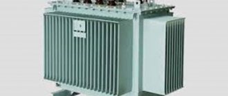
Electrical device design
Transformation of three-phase current does not necessarily imply the use of one transformer having a common magnetic circuit. Although such installations are widely used in the national economy.
There is the possibility of such a transformation using three separate single-phase transformers that are not magnetically connected to each other, that is, each individual phase will have its own separate magnetic circuit.
A transformer made according to this scheme is called a group transformer. The primary and secondary windings of the device are interfaced with each other according to one of the schemes adopted for transforming three-phase current.
Structurally, a three-phase transformer is a three-rod magnetic circuit with windings located on each of the rods, made in the same way as for single-phase devices.
Interesting material on the topic: how a toroidal transformer works.
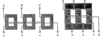
Let's imagine three single-phase transformers placed next to each other so that their three rods form one common central rod. On each of the other three rods there are primary and secondary windings.
The currents in the transformer coils will create time-varying magnetic fluxes, which will each be closed in its own magnetic circuit. In the central composite rod, the magnetic fluxes will add up and give a total of zero, because these fluxes are created by symmetrical three-phase currents, regarding which we know that the sum of their instantaneous values is equal to zero at any moment of time.
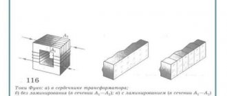
Let us assume that the primary coils of all transformer bars are exactly the same and wound in the same direction. We connect all the upper ends of the coils to neutral O, and connect the lower ends of the coils to the three terminals of the three-phase network. The magnetic cores are made of sheet electrical steel. To weaken eddy currents and reduce magnetization reversal losses, steel sheets are insulated with varnish before assembly.
Detailed design of a three-phase transformer.
Connection of transformer windings in a triangle
The triangle connection is so called because of its external resemblance to a triangle (seen in the figure).
When connected into a triangle, the following relations apply:
- linear currents are √3 times greater than phase currents
- line voltages are equal to phase voltages
The three secondary windings, when connected in a delta, are connected in series, thereby forming a closed circuit. There is no current in this circuit, since the EMF of the phases are shifted by 120 degrees and their sum at each moment of time is zero. Also, the current is zero if the following conditions are met: the EMF has a sinusoidal shape, the windings have the same number of turns.
Star and triangle in the question of third harmonics of transformers
In transformers, the triangle circuit is used, among other things, to obtain third harmonic currents, which are necessary to create a sinusoidal EMF of the secondary windings. In other words, to eliminate the third harmonic component in the magnetic flux.
To introduce third harmonics when connecting to a star, the neutral of the star is connected to the neutral of the generator, and the third harmonics begin to run along this path.
Magnetic Circuit Location
Three-phase core transformers are divided into transformers with a symmetrical magnetic circuit and transformers with an asymmetrical magnetic circuit. The arrangement of the rods in the same plane leads to the fact that the magnetic resistance for the middle phase flow is less than for the outer phase flows.
Indeed, the magnetic fluxes of the extreme phases travel along slightly longer paths than the flux of the middle phase. In addition, the flow of extreme phases, having left their rods, passes completely in one half of the yoke, and only in the other half (after branching into the middle rod) does half of it pass. The flow of the middle phase, upon exiting the vertical rod, immediately branches into two halves, and therefore only half of the flow of the middle phase passes through both parts of the yoke.
Thus, the flows of the extreme phases saturate the yoke to a greater extent than the flow of the middle phase, and therefore the magnetic resistance for the flows of the extreme phases is greater than for the flow of the middle phase.
A consequence of the inequality of magnetic resistances for the flows of different phases of a three-phase transformer is the inequality of no-load currents in individual phases at the same phase voltage. However, with low saturation of the iron of the yoke and good assembly of the iron of the rods, this inequality of currents is insignificant.
Since the design of transformers with an asymmetrical magnetic circuit is much simpler than that of a transformer with a symmetrical magnetic circuit, the first transformers found their primary application. Transformers with a symmetrical magnetic circuit are rare.
It will be interesting➡ What you need to know about current transformers
Main types of device
The main group of three-phase transformers are armored transformers. An armored three-phase transformer can be considered as consisting of three single-phase armored transformers, placed one next to the other with their yokes. It can be divided into three single-phase armored transformers, the magnetic fluxes of which can each be closed along its own magnetic circuit.
In core transformers, the windings are almost entirely open and therefore more accessible for inspection and repair, as well as for the cooling medium. There are a number of advantages and disadvantages based on which type of transformer is chosen.
Pros and cons of armored transformers over rod transformers.
The devices are switched according to various winding connection schemes. Group three-phase transformers are used in the presence of very high powers, from 630 kVA per phase.
Using a group transformer under such conditions is advisable because the dimensions and weight of the product are significantly smaller than a similar unit operating at the total power of the group.
Moreover, when using a single transformer, in order to have reserve power, you have to install another similar device, and in a group transformer, one of three single-phase ones can be used as a backup.
This determines the choice of group transformers for the stated purposes, despite the fact that they have lower efficiency, larger dimensions and are somewhat more expensive compared to single analogues.
You can read more about the design of transformers in the material on current transformers.
§ 79. Triangle connection
In addition to a star connection, generators, transformers, motors and other three-phase current consumers can be connected in a delta.
In Fig. 179 shows an uncoupled three-phase system. By combining the wires of an unconnected six-wire system in pairs and connecting the phases as indicated in the drawing, we move on to a three-phase three-wire system connected by a triangle.
Rice. 179. Uncoupled three-phase system
As can be seen from Fig. 180, the delta connection is made so that the end of phase A is connected to the beginning of phase B, the end of phase B is connected to the beginning of phase C, and the end of phase C is connected to the beginning of phase A. Line wires are connected to the phase connections.
Rice. 180. Connected three-phase delta-connected system
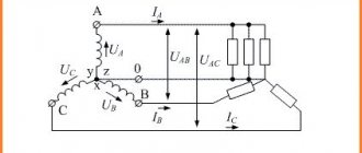
If the generator windings are connected by a triangle, then, as can be seen in Fig. 180, line voltage is created by each phase winding. For a delta-connected consumer, the line voltage is connected to the phase resistance terminals. Therefore, when connected by a triangle, the phase voltage is equal to the linear voltage:
Let us determine the relationship between phase and linear currents when connected by a triangle, if the load of the phases is the same in size and nature. We compose the current equations according to Kirchhoff’s first law for three nodal points A 1, B 1 and C 1 of the consumer:
From this it can be seen that the linear currents are equal to the geometric difference of the phase currents. With a symmetrical load, the phase currents are equal in magnitude and shifted one relative to the other by 120°. By subtracting the phase current vectors according to the resulting equations, we obtain linear currents (Fig. 181). The relationship between phase and line currents when connected in a triangle is shown in Fig. 182:
Rice. 181. Phase and line currents when connected by a triangle
Rice. 182. Dependence between phase and linear currents when connected by a triangle
Therefore, with a symmetrical delta-connected load, the line current is √3 times the phase current.
In Fig. 183 shows a vector diagram of currents and voltages for a uniform active-inductive load connected by a triangle. The diagram is constructed as follows. On the selected scale, we build an equilateral triangle of linear network voltages UAB, UBC AND UAC, which are equal to the phase voltages of the consumer. In the direction of the lag at angles φAB, φBC, φCA to the linear voltages UAB, U BC and UCA, we plot the phase current vectors IAB, IBC and ICA on a scale. Then, as stated earlier, we determine the line currents IA, IB and IC.
Rice. 183. Vector diagram of currents and voltages with a uniform load connected by a triangle
For motors and other consumers of three-phase current, in most cases, all six ends of the three windings are brought out, which, if desired, can be connected either by a star or a triangle. Usually a board made of insulating material (terminal board) is attached to a three-phase machine, to which all six ends are brought out.
Rod type magnetic core
To power radio-electronic devices, three-phase transformers with a common magnetic system through a yoke I for three phases with three rods C, or three-rod transformers are usually used. Each of the transformer windings, both primary and secondary, can be connected: a) by a star; b) a triangle.
When connected by a star, the ends of the windings form a common point 0. When connected by a triangle, the beginning of the first phase winding is connected to the end of the third, the beginning of the second - to the end of the first, and the beginning of the third - to the end of the second. In the first case, everything starts, and in the second, the common points of the windings are connected to the network.
It should be noted that the concepts of the beginning and end of the windings are conventional, but they are necessary for the correct connection of the phase windings. In three-phase transformers, the positive direction of the current from the beginning to the end of the winding must correspond to a certain direction of the magnetic flux in the rods; in core transformers this direction must be the same.
Winding connection: a - star; b - triangle.
The beginnings of high voltage (HV) phase windings are usually designated by capital (capital) letters A, B and C, and their ends by letters X, Y and Z, and for phase windings the letters AX, VU and CZ are used. The beginnings and ends of low voltage (LV) windings are designated, respectively, by lowercase (small) letters - a, b, c and x, y, g.
The most common winding connections are “star” (Y) and “delta” (D), and the primary and secondary windings can have either the same or different circuits. If, when connecting the windings with a star, the zero point is output, then such a connection is called “star with zero” (Yo).
Star connection of windings
The simplest and cheapest of them is to connect both windings of the transformer with a star (Y/Y), in which each of the windings and its insulation (with solid grounding of the neutral point) should be designed only for phase voltage and line current.
Star connection of transformer windings.
Since the number of turns of a transformer winding is directly proportional to the voltage, therefore, a star connection of the windings requires a smaller number of turns in each winding, but a larger cross-section of conductors with insulation designed only for phase voltage.
A three-phase transformer has windings connected in a star (Y/Y). This connection is widely used for small and medium power transformers (up to approximately 1800 kVA). The star connection is most desirable for high voltage, since in it the insulation of the windings is calculated only for the phase voltage. The higher the voltage and lower the current, the relatively more expensive it is to connect the windings with a delta.
Where is triangle winding used?
Connecting the windings with a triangle is structurally more convenient at high currents. For this reason, the Y/D connection is widely used for high power transformers where a neutral wire is not required on the low voltage side.
With three-phase transformation, only the ratio of phase voltages U1ph/U2ph is always approximately equal to the ratio of the numbers of turns of the primary and secondary windings w1/w2; As for linear voltages, their ratio depends on the method of connecting the transformer windings.
Connection of transformer windings with a triangle.
With the same connection method (Y/Y or D/D), the ratio of line voltages is also equal to the transformation ratio. However, with different connection methods (Y/D or D/Y), the line-to-line voltage ratio is √3 times less or more than this ratio. This makes it possible to regulate the secondary line voltage of the transformer by correspondingly changing the method of connecting its windings.
The operating characteristics of transformers are influenced by energy losses during heating of the windings in combination with other external and internal factors that significantly complicate the relationship of the secondary voltage shape with similar parameters of the primary circuit.
What are the differences
The main difference between the types of windings is the way they achieve and obtain different parameters of electrical voltage and current inside the motor. The first case involves a gradual increase in performance, the second option provides powerful current transmission.
The triangle and star methods differ in the implementation of the task. Often electricians use a combination of circuits. This gives a gentle mode for the wire or transformer, but at the same time the current takes on a smaller value.
Expert opinion
Karnaukh Ekaterina Vladimirovna
Graduated from the National University of Shipbuilding, majoring in Enterprise Economics
The triangle system, as a rule, is acceptable when connecting powerful mechanisms and the presence of large starting loads. If in this case you use a star rather than a triangle, you can cause damage to the engine. This is where the types of windings differ from each other.
Determination of device currents
When determining the primary winding current, losses should be taken into account, as well as the magnetizing current of the transformer, the relative magnitude of which in low-power power transformers is very significant. The current values can be determined using the following formula:
It will be interesting➡ Transformers for LED strips, expert opinion
where U1 and U2 are the voltages of the windings as specified;
P2 – power of the secondary winding as specified;
cos φ2 – load power factor according to the specification;
η – coefficient of performance (efficiency) of the transformer.
The choice of induction in the core rod and current density in the wires of the transformer windings - the permissible value of induction in the rod and yoke of the transformer core is determined by the selected value of the magnetizing current, power, frequency, type of transformer, number of joints in the core and the material of the latter.
You can read the article in more detail about the design of power transformers.
Connecting transformer windings in a zigzag
A zigzag connection is used when there is uneven load on the secondary loads. After the zigzag connection, the load is distributed more evenly across the phases and the magnetic flux of the transformer remains in balance despite the uneven load.
Consider the zigzag star connection of a three-phase power transformer. A schematic representation is shown in the figure.
The primary windings are connected in a star. Next, we divide each secondary winding in half. And then we connect as shown in the figure.
When connecting into a zigzag star, a larger number of turns will be required than with a simple star. Also, with this connection it is possible to obtain three voltage classes, for example 380-220-127V.
Bookmark or share with friends
Source: pomegerim.ru
Transformer power circuits
The permissible current density in the wires of the transformer windings largely determines the weight and cost of the latter. The higher the current density in the windings, the lower their copper weight and, accordingly, the cost of the transformer. On the other hand, with increasing current density, losses in the copper of the windings and heating of the transformer increase.
Power supply diagram for a traction network of a 2×25 kV system using a three-phase transformer with step-up autotransformers.
The simplest is the power supply circuit for the traction network of a 2×25 kV system using a three-phase transformer and step-up autotransformers. A special feature of the circuit is that to increase the voltage to 55 kV, a conventional linear autotransformer AT is used, which is connected to the contact network and the supply wire, and transformer T is connected between the contact network and the rails.
Autotransformers are installed on the terminals of a 27.5 kV transformer or on the feeders of the contact network. The latter option is preferable, since it allows you to have only contact network buses at the substation, and autotransformers can be installed outside the territory of the traction substation.
In the scheme, a significantly larger part of the electricity is supplied to electric locomotives directly along the contact network - rails circuit, bypassing the step-up autotransformer.
This circumstance makes it possible to install step-up autotransformers at a substation of the same power as in the feeder zone, and not reserve them at the substation. When the autotransformer at the substation is disconnected, the autotransformer closest to the substation in the feeder zone takes on the role of step-up.
How to increase energy transfer
It is possible to increase the transmission of electricity along the supply wire-rail circuit by installing special step-up autotransformers at substations, the power of which corresponds to the load of the substation power arm, or by specially connecting two standard three-phase transformers at the substation.
The U/D-1 connection group of the second transformer is obtained by the same double relabeling of the terminals of the two phases of the primary and traction windings of the standard transformer. The designation of the secondary winding terminals according to the factory markings is shown in the figure with the index “T”.
The same terminal of the traction winding of both transformers is connected to the rails, as in the 25 kV system (terminal st according to the factory marking). The connection with the st output rails determines that the windings on the middle rod will be the least loaded for both transformers.
By analogy with three-phase transformers in a 25 kV system, if a wire is connected to terminal at, we have a positive voltage of this wire relative to the rails, and to terminal bm, we have a negative voltage of the wire relative to the rails.
Power supply diagram for the traction network of a 2×25 kV system with a series connection of two phases of three-phase transformers (a), vector diagrams of the voltages of the primary and secondary windings (b).
The first transformer is connected by its terminal am to the contact network of the first feeder zone, and by its terminal bm to the contact network of the second feeder zone.
The second transformer has a reverse connection: with its terminal yat it is connected to the supply wire of the second feeder zone, and with its terminal bm - to the supply wire of the first feeder zone.
The sequential connection of two secondary windings of transformers with winding connection groups U/D-11 and U/D-1 makes it possible to obtain double the voltage of the two phases supplying the traction network on opposite sides of the substation.
It will be interesting➡ What are isolation transformers
As above, at the contact network and the supply wire, and the voltages of the supply line are indicated, with which the voltage of the contact network and the supply wire coincide in phase. The latter are shifted by 180°. Therefore, the figure shows the position of only the contact line-rail voltages. It does not differ from the position of these vectors in a 25 kV system, if in a 2x25 kV system the transformer connected to the contact network is connected to the same phases of the supply line as in the 25 kV system.
INCLUSION OF ENERGY RECEIVERS INTO THE THREE-PHASE CURRENT NETWORK
Electric lamps are manufactured for rated voltages of 127 and 220 V, and three-phase electric motors for rated phase voltages of 127, 220 and 380 V
and higher.
The method of connecting the receiver to a three-phase current network depends on the line voltage of the network and on the rated voltage of the receiver.
Lamps with a nominal voltage of 127 V
switched on by a triangle at a linear network voltage of 127
V
and a star with a neutral wire at a linear network voltage of 220
V.
Lamps with a rated voltage of 220
V
are connected by a triangle into a network with a linear voltage of 220
V
and a star with a neutral wire into a network with a linear voltage of 380
V.
A three-phase electric motor is connected by a delta into a network whose line voltage is equal to the rated phase voltage of the electric motor. If the line voltage of the network exceeds √3 times the rated phase voltage of the electric motor, then it is turned on as a star.
Article on the topic Connecting energy receivers with a triangle
Scheme of operation when one of the transformers is disconnected
In the event that a transformer connected to the supply wire buses is disconnected at the substation, we will have the circuit practically considered in the figure with step-up autotransformers, the role of which is played by the autotransformers closest to the substation in the feeder zones.
At the same time, in the sections from the substation to the autotransformers closest to it we have a 25 kV system, and in most of both feeder zones the 2x25 kV system remains. Since the resistance of sections with a 25 kV system is greater than their resistance with a 2x25 kV system, neighboring substations take on a greater load.
If a transformer connected to the contact network buses is disconnected at a substation, the autotransformers closest to the substation will operate in transformer mode and, with significant traffic volumes or heavy trains, may be overloaded.
Scheme of operation when one of the transformers is turned off.
This can be avoided either by switching to one-way power supply to feeder zones from neighboring substations during the shutdown of the specified transformer, or by bringing the connection group of an operational transformer into correspondence with the group of the disconnected transformer and connecting it to the contact network buses.
To do this, it should be possible to quickly switch two phases on the primary side of the transformer connected in normal mode to the supply wire buses.
If it is necessary to have a greater degree of redundancy of transformers, it is possible, as in the case of single-phase transformers, to use a third three-phase transformer as a backup with the ability to connect it to the 110 (220) kV buses and to the buses of the contact network or supply wire instead of any transformer taken out of operation.
The considered schemes of substations with three-phase transformers are promising on the roads of the CIS countries at the junction of 25 and 2×25 kV systems and at traction substations, if necessary, to power a large regional load from them, as well as when strengthening the power supply system of previously electrified lines.
Application area
These devices are designed to convert the operational parameters of three-phase electrical networks and are used in the following types of power systems:
- electricity transportation and distribution systems;
- converting devices;
- electrical technological installations (welding equipment, electric furnaces, etc.);
- communication and telemechanics devices;
- automation systems;
- household electrical equipment;
- electrical measuring devices.
A suitable connection diagram is determined in accordance with the operating conditions of the device, which include network power, voltage level, and load asymmetry. The choice of connection scheme is also influenced by economic considerations.
Checking the device
The belonging of a transformer to one or another connection group can be determined using a polarometer-voltmeter of the magnetoelectric system with zero in the middle of the scale and the polarity of its terminals marked.
Each group of connections corresponds to a specific table of polarometer needle deviations for the transformer under test and, after comparing it with the existing ones, a group of winding connections is established.
When the HV windings are switched on to a constant voltage of a certain polarity, an instantaneous EMF is induced in the other windings of the transformer at the moment of switching on, the magnitude and direction of which depend on the group of connections of the windings and are recorded using a polarometer.
The video below discusses in detail the operating principle of a three-phase transformer and its structure.
Quick comparison table
Both options are used in the electrical field. These are proven winding systems that help maintain power while also reducing wear.
It is better to compare schemes using the same properties - it becomes clearer why one should choose one or another option.
| Criterion | Star | Triangle |
| Voltage | 330 V | 220 or 380 V |
| Number of output wires | 3 | 6 |
Expert opinion
Karnaukh Ekaterina Vladimirovna
Graduated from the National University of Shipbuilding, majoring in Enterprise Economics
There is an alternative option when the circuit combines both types of winding. That is, there is a switch from star to triangle or vice versa. This technique is suitable for phase motors with a starting rotor.