A circuit breaker is a convenient and practical replacement for fuses, which not only has higher tripping accuracy, but can also be used a large number of times. How to properly connect a machine is a question that not only novice electricians, but also every self-respecting owner of a private house or apartment should understand. And this article will not only tell you how to install an automatic or differential switch, but will also introduce readers to the variety of switching equipment and the operating principle of package switches.
Typical installation mistakes
Most often, when installing electrical wiring, and in particular connecting a machine, the following mistakes are made:
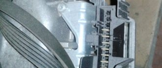
- The power wire is inserted from below. Despite the fact that this electrical installation option is not prohibited by the PUE rules, we still do not recommend connecting the circuit breaker from below, especially since even on the front panel of the case there is a diagram in which the installation location of the fixed contact is at the top (as shown in the photo below) .
- The contacts are clamped too tightly with the fixing screw. This should not be allowed, because as a result, you can not only damage the cable core, but also deform the body of the product.
- The conductors are not connected correctly. A prerequisite is that the phase must be connected under the phase, zero under zero (if a two-pole switch is used). We immediately recommend that you familiarize yourself with the material: color coding of wires.
- Instead of one two-pole circuit breaker, two single-pole circuit breakers are used. This is strictly prohibited, because... phase and zero must be disconnected at the same time.
- When fixing the core, insulation gets into the seat. Be sure to strip the wire as much as required by the model data sheet. If you press down on the insulation with a screw, the contact of the conductor will weaken, as a result of which the core will heat up and further adverse consequences will occur. For this task, we recommend using a special tool for removing insulation.
- The choice of circuit breaker is incorrect; in particular, the product is not able to withstand the incoming loads. In this case, first you need to correctly calculate the cable cross-section and, according to the calculated characteristics, select the appropriate model.
- When calculating a suitable circuit breaker, the value is rounded up. For example, you calculated that the current load on the product is 19 Amperes. According to the simplest logic, novice electricians go to the store and purchase a device of the closest value for connection - 20 Amperes. This is a huge mistake, because... the calculated value is nominal, and it turns out that the protection will operate when the wiring is slightly overloaded. It is better to purchase a switch with a rating of 16 Amps, so the electrical wiring will last longer.
Another important point on which there is a lot of discussion is whether it is possible to connect the machine in front of the electricity meter or is this done only after it? The answer is that it is possible, and even necessary, the main thing is to buy a special box, which is sealed by energy sales representatives. Installing an input machine in front of the electric meter will allow you to safely replace the electricity control device both in a private house and in an apartment.
Here, in fact, are the rules for installing and connecting an electrical machine with your own hands. Now let's move on to the main topic of the article.
Enter from above or below
A very important question that worries both many electricians and just home craftsmen: how to connect the machine, from above or from below? To answer this, you will have to refer to the regulatory documentation, namely, the Rules for the Construction of Electrical Installations.
Paragraph 3.1.6 states that the machine should be connected to the electrical network from the side of the device on which the fixed contact is located. This means that the voltage in a single-phase or three-phase network must be on the side of the switch that does not break the electrical circuit. Paragraph 3.1.6 applies to many types of switching equipment. This can be not only a single-contact, but also a two-pole or three-phase circuit breaker, as well as a differential package or RCD.
You can find out the location of this contact only by disassembling the bag, which is not very convenient every time you replace it in the apartment. But the design of all machines is almost the same, so you should find out where the fixed contact is located on only one switch. And it is located on top, so the connection of a single-pole or two-pole circuit breaker must also be done from above.
If you happen to have a packet from an unknown manufacturer in your hands, then just look at its body, or more precisely, the front panel. In this place, most often all the necessary information is placed on the machine, such as the model, accuracy class, and connection diagram of the circuit breaker with the exact location of the moving and fixed contacts.
Conclusion: the connection of the circuit breaker to the electrical network must be done from above. This is what the regulations say, which help avoid unnecessary confusion. But if you look from the technical side: is the difference in connecting the power cable significant? Answer: no, it does not matter at all from which side the operating voltage is supplied to the package. The device will work properly both with connections from above and from below.
Wiring
Ideally, if the machines are located next to each other on a DIN rail, then these distances can be measured simply by attaching a conductor so that the transition part from one machine to another forms a loop. This will allow the wire to exit the housing vertically.
The stripped area should be twice as long as the end of the wire, because we will have to make a small loop out of it, which will be used to connect the machine. You will need to put heat-shrink tubing on this loop or tightly wrap it with electrical tape at the place where the insulation ends. This will give our wire rigidity.
Then the loop must be inserted into the contact hole of the machine and tightened tightly. The cleaned areas should correspond to the number of circuit breakers. But we will be sure that the phase is separated correctly - the same for the apartment.
Standards for connecting the machine in the panel according to the PUE
Government authorities have requirements for shields and their installation that are specified in the PUE and must comply with GOST 51778-2001:
- the installed shield must comply with the documentation, which clearly reflects the number of machines and their power, as well as the class and degree of protection;
- the voltage symbol should be installed on the lid - 380V or 220V;
- the phase must be connected to a fixed contact;
- material of manufacture – metal or plastic coated with non-flammable paint;
- make markings on the wires indicating the devices that are connected;
- install jumpers from bus drives between the machines;
- There must be grounding of the box body. The case must have ears so that the electrical inspector can install the necessary seals.
We assemble the shield in the apartment and house ourselves
An electrical panel in a private house, country house, or apartment performs a dual function: it provides input and distribution of electricity and creates safe operating conditions. If you want to understand a difficult issue, you can assemble the electrical panel yourself. The input machine and the meter must be installed by representatives of the electricity supply organization, but then, after the meter, you can assemble the circuit yourself (although they do not like to lose money). True, before putting the house into operation, you will need to invite them so that they are present during the start-up, check everything and measure the ground loop. All of these are paid services, but they cost much less than a complete panel assembly. If you do everything correctly and according to the standards, it will turn out even better on your own: after all, you are doing it for yourself.
Why is electrical knowledge necessary?
Information about electrical devices known from school physics lessons is not enough for practical use.
The average consumer more often encounters circuit breakers, since they are the ones that trip due to network overloads. It is not enough to simply return the lever to its usual position; you must definitely understand the reasons for the shutdown, otherwise the situation may repeat itself in the near future.
To navigate the electrical panel (which, by the way, is a mandatory element of the energy system of private houses), you need to know the composition and purpose of all devices - pulse relays, load switches, RCDs, etc.
Do you need to be able to change the automation yourself? We recommend that you first study the theory, and at the first shutdown, practice.
The fact is that it is not always possible to get quick help from professionals: on days off, electricians rest like everyone else. And if the house is located in a country house or in a village, it is better to become thoroughly familiar with the electrical network and related devices.
Purpose of boxes for machines
Plastic and metal boxes perform the same function as distribution boards - they organize the operation of electrical equipment and serve for the electrical installation of protective devices. In the specialized literature you can find other names: box, box, shield, panel.
The main “filling” for filling the box is made up of electric machines, however, other protective devices - RCDs and difautomatic devices - can be located next to them.
There are no products for sale with pre-installed equipment. Low-voltage boxes are sold empty, and automatic protection devices are selected taking into account the characteristics of the network and installed according to the selected scheme
Large boxes contain indicators, switches, timers, differential relays. But to equip the network of a private house or one apartment, installation of additional equipment is not necessary.
If, in addition to protective equipment, an electricity meter is installed inside the box, then the panel goes from the distribution category to the metering and distribution category
Boxes are installed in apartments, on floor areas, as well as on the street, if it is necessary to connect a private home to the power supply line. They are varied in design, assembly and functions.
Instructions for connecting a two-pole circuit breaker
Now let’s try to figure out how to connect a two-pole circuit breaker to a 220 V household electrical circuit. This means that there will be 2 wires at the input - phase and zero.
The wire required for connection has 3 cores with a cross-section of 2.5 mm (VVGngP 3*2.5), therefore, the maximum permissible continuous current is 25 A.
Working elements of the device
We have chosen a two-pole automatic protection device, which looks like this:
We will need four contacts, two of which are at the top (incoming), two at the bottom (outgoing). Fastening will occur using mounting screws that secure the pressure plates
There is a hint on the surface of the case - a connection diagram for the machine.
Based on the markings, we determined that the machine corresponds to the wire cross-section - C40. This means that a current of 40 A is the maximum response current of the device
The device is mounted on a metal plate – DIN rail.
If you look from the back, you can see a latch with which the machine is fixed to the DIN rail in one movement
Now that we've figured out the components, let's move on to the instructions.
Step-by-step photo instructions for connection
We turn off the voltage in the network and check its absence using a multimeter. We prepare wires that have double insulation. Three wires of different colors are hidden under the layer of external protection. The color correspondence is as follows: black – phase, blue – zero, yellow – ground.
We only need 2 wires - phase and neutral, the third (ground) will go separately. Remove the insulation 1 cm and insert the bare ends of the wires into the terminals
The phase should be on the left, zero should be on the right
Please ensure that some of the insulation does not come into contact - when heated, the cable may melt and cause damage to the device.
Carefully tighten the screws and proceed to grounding
To secure the grounding, we use a feed-through contact, which is fixed on the DIN rail in the same way as the circuit breaker itself. Insert the third wire and clamp it
The next step is to connect the outgoing wires, which are attached to the lower terminals.
In the same way, remove the insulation, insert the ends into the terminals and clamp them carefully so as not to damage the device body. Next we fix the ground wire
The connection is complete. All that remains is to apply voltage, move the control lever to the active position and check the operation.
Circuit breakers: design and principle of operation
Before we consider the procedure for connecting circuit breakers in an electrical panel, let’s figure out how they are designed and on what principle they are triggered.
The product includes the following elements:
- Frame.
- Control system.
- Top and bottom terminals.
- Switching device.
- Arcing chamber.
Fire-resistant plastic is used as material for the manufacture of the housing and control system. The switching device contains moving contacts as well as fixed contacts.
An arc-extinguishing chamber is installed on a pair of contacts, which are the pole of the packetizer. When the contacts break under load, an electric arc occurs, which is extinguished by the camera. The latter consists of steel plates, insulated from each other and located at the same distance. The chamber plates help cool and extinguish the electric arc that appears during malfunctions. Machines can have one, two or four pairs of contacts.
Two-pole circuit breakers have two pairs of contacts: one is movable, the other is fixed.
Such a switch is equipped with a position indicator, which makes it easy to find out whether the machine is on (red light) or off (green).
The operating principle of circuit breakers is clearly shown in the video:
Step-by-step instructions on how to connect a single-core wire
After you have purchased the RCD and all the necessary devices for installation, you can begin to work. It must be remembered that all stages of installation must be carried out sequentially and all safety measures must be taken.
Practical advice
Experienced electricians recommend installation in the following sequence:
- de-energize the shield. Check the presence of current using the indicator;
- care must be taken to ensure that no one unexpectedly turns on the electricity;
- the equipment must be firmly snapped onto the DIN rail;
- Electricians recommend connecting the device according to this principle - all incoming wires are at the top, and outgoing wires are at the bottom. This generally accepted scheme will help avoid confusion when replacing equipment;
- there should be no kinks in the wiring when connecting;
- disconnect excess parts of the cable with wire cutters;
- Carefully remove the insulation from the cable by 10 mm;
- Install the cable into the required terminals and secure it. It is necessary to monitor the clamping force - tightly twisted terminals will quickly lead to breakage of the switch;
- turn on the power supply;
- check the voltage access to the switch using an indicator.
Common Mistakes
Sometimes it happens that the power switch does not perform its functions, so you have to reinstall it again. To avoid malfunctions, you need to avoid the following installation errors:
- the insulation from the wire has come into contact. If the insulation is not removed before installation, this increases the risk of a short circuit that leads to a fire;
- connecting several wires with different cross-sections to one terminal. In this case, only a large cross-section core is tightened well, and thin wires have poor contact, which leads to melting of the housing and a fire. This happens when connecting various devices to the switch. To avoid this, you need to use jumpers between cables and devices. They are made from wires of the same cross-section;
- Do not connect copper and aluminum wires together. The device will become unusable due to the oxidation process when two metals are combined;
- You should not connect a straight wire to the terminal, but you need to bend it with a hook, which will increase the contact area and increase the performance of the device; such a cable is also more difficult to pull out of the device.
Drawing up an electrical panel diagram
An important step in installing an electrical panel is creating its diagram. There are several explanations for this. Let's say, if you plan to repair or modernize the wiring in your apartment in the future, using the diagram you can quickly establish what each machine and part in the panel is responsible for. You will also need the diagram when accepting work as an electrician. In addition, connecting wires with such a diagram on hand is much easier. You can either draw it manually or in specialized programs, and then print it.
The electrical circuit is created in several stages. The first step is to find out what kind of electrical system is in the house, then divide all points of electricity consumption into several categories. After this, based on the existing data, a shield diagram is created
It is extremely important that the diagram used symbols, which are described in detail in GOST 21.614 “Conventional graphic images of electrical equipment and wiring in the original”
So, as mentioned above, all work begins with determining the power supply and grounding system in the apartment, since the connection of the panel will depend on this. You can find out by looking at the sign on the floor or by going to the housing office. Often, three systems TN-C, TN-S, TN-C-S are installed in residential buildings.
It is worth immediately noting that the first system was created according to old GOST standards and was used in houses that were built before 1998. The TN-C system is represented by two-core copper or aluminum wiring. A three-phase cable (L) with one conductor PEN, in which ground and neutral were combined, went to the floor distribution board. The last two systems are used in modern homes. A three-core copper wire is laid in the apartment, and a cable with three phases (L), neutral (N) and PE ground (S) is connected to the switchboard.
How to connect the phase and neutral wires
Simultaneous disconnection of phase and neutral is justified especially in situations where three-phase voltage is introduced into a house or non-residential building. In such situations, there is a greater risk that one of the phases may short circuit to zero. This is a short circuit mode to which the machine protecting this phase must respond. But in those fractions of a second while it is triggered, an overvoltage will occur in the other two phases. That is, instead of the required 220 V, there may be all 380 V - the voltage difference between the two phases with a conventional three-phase connection.
Not a single household appliance is designed for such voltage, and the more powerful it is, the more current it passes, and the greater the likelihood of it burning out due to overvoltage. Where the fuse of a low-power device immediately blows, powerful equipment will still “tolerate” a heavy load for some time, and during this time the switching power supply or transformer may fail. Therefore, it is preferable to protect equipment such as boilers, dishwashers and washing machines with two-pole circuit breakers that cut two circuits at once.
Keep in mind that phase imbalance is also harmful to the source that powers the building. A generator, a transformer booth, a substation - all this will deteriorate very soon. For such purposes, there are special three-phase circuit breakers, which, in the event of a large imbalance or failure in one of the phases, can immediately turn off all three phases simultaneously. For more critical circuits, it is recommended to connect a four-phase circuit breaker, which also de-energizes the neutral wire.
Selection of RCDs and automatic devices
The circuit breaker provides short-circuit protection, but it is not capable of detecting leakage current that may flow into the electrical equipment frame when the insulation coating is broken or through the human body. For these purposes, a residual current device (RCD) or differential circuit breaker is connected to the panel.
These devices are switching devices that constantly monitor the differential current of the electrical wiring, and if it deviates from the permissible value, a shutdown is performed. The principle of operation is clearly illustrated in the picture.
How does an RCD work?
The main purpose of these devices is to provide adequate protection in the event that a person becomes energized and to prevent fire that may be caused by a leak.
Main characteristics of the devices:
- rated current parameters (they must correspond to the circuit breaker or a higher value is allowed);
- operating voltage (220V or 380V, respectively, for single-phase and three-phase devices);
- The permissible leakage current parameter for household devices is considered safe 30mA.
In our circuit, it is necessary to install a 16A RCD with a permissible leakage current of 30mA (elements C – F). These differential protection devices do not need to be installed for hallway and kitchen lighting.
RCD for 16A
How to choose a machine?
Before you begin installing protective circuit breakers, you need to select them and also understand the intricacies of connection. People who want to know how to wire a circuit breaker ask various questions. For example, are the circuit breakers in the distribution board connected before or after the meter? Should an automatic input be installed? These and other connection nuances are of interest to users.
Basic parameters of circuit breakers
The characteristics of circuit breakers include:
- Rated current value (in Amperes).
- Operating voltage of the electrical network (in Volts).
- Maximum short circuit current.
- Ultimate switching capacity.
- Number of poles.
The maximum switching capacity is characterized by the maximum permissible value at which the switch is capable of operating. The PKS of household devices can be 4.5, 6 or 10 kA.
When choosing, they are most often guided by such basic indicators as short-circuit shutdown current, as well as overload current.
The cause of overload is the connection to the electrical network of devices with excessively high total power, which leads to exceeding the permissible temperature of contact connections and cables.
Taking this into account, it is necessary to install a packet in the circuit, the value of the shutdown current of which is not less than the calculated value, and better - if it slightly exceeds it. To determine the calculated current, you need to sum up the power of the devices that are supposed to be connected to the circuit (for each of them this indicator is available in the passport). The resulting number must be divided by 220 (the standard voltage value in a household network). The result obtained will be the value of the overload current. It should also be taken into account that it should not exceed the current rating that the wire can withstand.
The magnitude of the shutdown current during a short circuit is the indicator at which the circuit breaker is switched off. The short-circuit current is calculated when designing the line using formulas and reference tables, as well as using special equipment. Based on the obtained value, the type of protection is determined. At small sites and in household networks, type B or C machines are used.
Methods for installing RCDs
There are two possible ways to install the device. The first option involves installing a common RCD in the electrical wiring diagram, immediately behind the meter and the machine. With one common RCD for an apartment or house, it is very difficult to find the place of current leakage through the insulation of the wires. Such a violation of insulation should be looked for throughout the apartment or cottage.
Variant of electrical wiring diagram with a common RCD and protective grounding in a single-phase network
In this case, the RCD will de-energize the entire apartment. In another option, several RCDs are installed, separately for each direction of electrical wiring, in the living room, kitchen, bedroom and children's room. This circuit of separate electrical wiring for rooms is assembled in the electrical panel in the hallway.
Several RCDs are installed in the same electrical panel. This option is of course expensive, but it has some advantages. Firstly, when the RCD is triggered, the network will be turned off in only one direction, and in the other part of the apartment the network voltage will remain. It will be easier to look for electrical damage in one room.
Electrical wiring diagram option with a separate RCD for sockets and protective grounding in a single-phase network
In a children's room, a separately connected RCD device will protect children from touching a dangerous socket faster than in the version of a common RCD. For the children's room option, an RCD with a shutdown current of less than 10 mA is installed. In the bathroom or kitchen where the washing machine is located, you need to install an RCD with a high response current (300mA - 500mA), because an RCD with a shutdown current of 10 mA will constantly turn off the kitchen.
The RCD is selected according to the optimal current for all loads in amperes. The response time of an RCD - a high-quality device - is up to 0.1 seconds, during which time an electric shock is not felt. The protection device must be checked for functionality by pressing the RCD test button once a month and after each emergency operation.
The machine has turned off: what to do?
An inexperienced user, when a circuit breaker trips and the lights go out, rushes to restore the operation of household appliances, so he simply opens the protective cover and turns on the device. However, this is not an entirely correct solution; it is better to first find out the reason for the shutdown.
The first thing that needs to be done is to check the connected household units and devices, paying attention to the appearance of sockets and plugs, the presence or absence of the smell of burnt plastic. Forks that are too hot should also be a warning.
One of the common reasons is an increase in energy load. If your washing machine and microwave are working, and when you turn on the vacuum cleaner, the protection is triggered, then an operational overload has occurred. There is only one solution - to evenly distribute the load, that is, turn on powerful devices one at a time.
If only one of several devices constantly responds, check the serviceability of all devices related to this circuit (a light bulb has burned out, a short circuit has occurred). The reason may lie in the wiring - in this case, be sure to invite an electrician
If the number of devices has not increased, the load has not changed, and a shutdown occurs, the high temperature may be to blame. When the temperature in the panel increases, the machine may also operate.
And the last reason is the failure of the circuit breaker itself. After several reactions to a series of increased currents, short-circuit faults, and arc extinguishing, it becomes unusable, which can be determined by external signs. If the terminals are charred or the plastic has melted, the device must be replaced.
Installation and connection of elements
All modern automatic devices and RCDs have a unified mounting for a standard mounting rail (DIN rail). On the back they have a plastic stop that snaps onto the bar. Place the device on the rail, hooking it with the recess on the back wall, and press the lower part with your finger. Once clicked, the item is installed. All that remains is to connect it. They do it according to the scheme. The corresponding wires are inserted into the terminals and the contact is pressed with a screwdriver, tightening the screw. There is no need to tighten it too much - you can squeeze the wire.
They operate with the power off, all switches are turned to the “off” position. Try not to handle wires with both hands. Having connected several elements, turn on the power (input switch), then turn on the installed elements one by one, checking them for the absence of a short circuit (short circuit).
Connecting the input machine and RCD
The phase from the input is supplied to the input circuit breaker, from its output it goes to the corresponding input of the RCD (place a jumper with a copper wire of the selected cross-section). In some circuits, the neutral wire from the water is supplied directly to the corresponding input of the RCD, and from its output it goes to the bus. The phase wire from the output of the protective device is connected to the connecting comb of the machines.
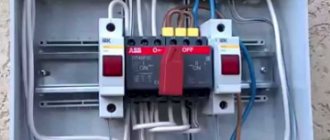
In modern circuits, the input circuit breaker is set to two-pole. he must simultaneously disconnect both wires so that in the event of a malfunction, the network is completely de-energized: this is safer and these are the latest electrical safety requirements. Then the circuit diagram for switching on the RCD looks like in the photo below.
When using a two-pole input circuit breaker
To learn how to install an RCD on a DIN rail, watch the video.
In any circuit, the protective grounding wire is connected to its own bus, where similar conductors from electrical appliances are connected
Grounding is a sign of a secure network and doing so is vital. Literally
To learn how to properly connect an RCD, watch the video tutorial.
When assembling the panel yourself, please note that the input machine and the meter will be sealed by the energy supply organization. If the meter has a special screw onto which a seal is attached, then the input machine does not have such devices. If it is not possible to seal it, you will either be denied entry or the entire panel will be sealed. Therefore, inside the common panel, a box is placed in one or two places (depending on the size and type of machine), and the input machine is mounted in it. This box is sealed upon acceptance.
Individual automatic machines are installed on the rails exactly like an RCD: they are pressed against the rail until it clicks. Depending on the type of machine (one or two poles - wires), the corresponding wires are connected to them. What kind of machines there are, and how devices for one and three-phase networks differ, see the video.
After the required number of devices are installed on the mounting rail, their inputs are connected. As they said earlier, this can be done with wire jumpers or a special connecting comb. See the photo for what the wire connections look like.
The machines in one group are connected by jumpers: the common phase arrives
There are two ways to make jumpers:
- Cut the conductors into the required sections, expose their edges and bend them in an arc. Insert two conductors into one terminal, then tighten.
- Take a long enough conductor and strip off 1-1.5 cm of insulation every 4-5 cm. Take pliers and bend the exposed conductors so that you get interconnected arcs. Insert these exposed areas into the appropriate sockets and tighten.
They do this, but electricians say the quality of the connection is poor. It is safer to use special tires. Under them on the case there are special connectors (narrow slots, closer to the front edge), into which bus contacts are inserted. These tires are sold by the meter and cut into pieces of the required length using ordinary wire cutters. Having inserted it and installed the supply conductor in the first of the machines, tighten the contacts on all connected devices. Watch the video on how to connect machines in a panel using a bus.
A phase wire is connected to the output of the machines, which goes to the load: to household appliances, to sockets, switches, etc. Actually, the assembly of the shield is completed.
Where is the electrical panel for the meter and automation installed?
The first step is to decide on a place to install the shield. So, experts believe that it is better to fix it near the entrance door in the corridor, because then you will not have to lay the cable from the landing, which will greatly simplify installation.
As a rule, the shield is fixed at the level of visibility of the residents of the apartment - this will allow you to easily take readings and turn off the machines. Therefore, the installation location will differ depending on the height of the household.
Note! There are still electricians who prefer to install meters under the ceiling (as they did before). Old designs were fixed to the wall without drawers, so they were fixed at a height for safety reasons.
Electrical panel in the apartment
Any modern shields have a secure base and are closed with a lock , so strangers or small children will not be able to get there if they do not have access to the keys.
When choosing a location for installation, they also take into account where the cable of the overhead or underground power line will pass from (in an apartment or private house). You can check this information with the employees of the company responsible for electricity.
Buy a ready-made electrical panel or assemble it yourself
Now electricians not only assemble the panels themselves, but also install a ready-made factory version with all the internal contents. Such designs are even made to special order for a specific apartment.
The main point in this matter is the experience of installing branded shields. If the master has already encountered such installation, then there is no need to be afraid. In other cases, it is better to assemble the structure on site, in stages.
Prices for electrical panels
Electrical panel
Video - Assembling a panel for an apartment
Connection methods
Single-phase circuits
In order to answer the question posed earlier, one should proceed from the requirements of the PUE, which regulate the procedure for switching on the combination of an automatic machine plus an RCD. According to the provisions of this document, the protection device is connected as shown in the figure below.
Connection diagram for a single-phase RCD
When considering it, the following conclusions can be drawn:
- In a single-phase network, this device is almost always installed immediately after the meter;
- Line switches (automatic machines) are connected to its output, from which wiring is distributed throughout the apartment;
- The zero bus is connected from the corresponding output terminal of the meter to the second pole of the RCD;
Important! In this situation, special attention should be paid to the fact that the RCD is connected after the meter and before the machine with two wires: forward and reverse (this point is very important from the point of view of the possibility of its operation). You should also pay attention to the fact that the connection diagram for the uzo and the machine assumes the presence of a single-pole current switch. In this case, the neutral conductor coming from the meter or RCD is connected to a common ground bus (OGB), bypassing the machines, and from it is routed along separate lines paired with a phase wire
In this case, the neutral conductor coming from the meter or RCD is connected to a common ground bus (OGB), bypassing the machines, and from it is routed along separate lines paired with a phase wire
You should also pay attention to the fact that the connection diagram for the uzo and the machine assumes the presence of a single-pole current switch. In this case, the neutral conductor coming from the meter or RCD is connected to a common ground bus (OGB), bypassing the machines, and from it is routed along separate lines paired with a phase wire
Regarding the rules for connecting conductors to the device, the following should be noted. Like a circuit breaker, the incoming wires come from the top of the protection device, and the outlet wires from the bottom.
Three-phase network
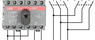
A typical connection diagram for a three-phase device assumes the presence of 3 groups of input and output contacts, each of which forms a protection chain for one of the phases (see photo below).
Connection diagram for a three-phase RCD
Additional Information. The figure shows that in real power circuits the number of RCD input and output contacts is limited to four (three phases plus ground).
The latter is explained by the fact that the earth conductor for all three phase lines is common (it is highlighted in blue in the figure).
Design of a standard circuit breaker
For example, we will use the BA47-29 series switch as the most popular switching device with an affordable pricing policy. Before you learn how to properly connect a circuit breaker to a single-phase network, you need to consider its design.
The BA47-29 series circuit breaker consists of the following elements:
- A copper terminal connected to a fixed power contact. Most often, the supply wire is installed exactly in this place.
- The movable contact, which makes the switching, and the copper stranded conductor, has a sufficiently large cross-section.
- Arc chamber.
- A special thin plate with a hole through which gases formed after the arc escape.
- An electromagnetic release, presented in the form of a simple coil. The stranded conductor from the moving contact is soldered to the coil.
- Plastic, fully dielectric handle.
- A bimetallic plate that acts as a thermal release. The plate is located immediately behind the reel.
- A special screw for adjusting the bimetallic plate. The screw is not installed on all models, and adjustment is made at the manufacturer.
- The lower copper terminal, from which the conductor goes directly to the consumer.
A three-phase machine has a similar design, but instead of one terminal, it uses three, isolated from each other.