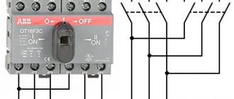
Electrical energy on an industrial scale cannot be transmitted in the form of single-phase alternating current. For this purpose, three-phase current is used, and three-phase transformers are used for its transmission. One of the ways to transform three-phase current is the use of three single-phase transformers.
The connection of the primary and secondary windings in these devices is carried out in one of the three-phase systems - star or delta. It is on this principle that powerful single-phase transformers operate, which are equipped in large power plants. Their primary windings are connected to the corresponding phases of the generators, and the secondary windings, connected in a star, are connected to the corresponding phases of the power lines.
Definitions
Medium power three-phase power transformer - no more than 33.3 MVA with a short-circuit impedance not higher than 25 - 0.3N/W%. N is the rated power of the transformer (MVA), W is the number of core bars.
Large three-phase power transformer - power up to 100 MVA, with an impedance higher than that determined by the formula specified for the previous class of products.
Distribution three-phase transformer - step-down, power up to 2.5 MVA, with separate windings and ON type cooling.
Star connection
It is recommended to consider this type of connection using the example of a star-star circuit. In this case, the current source and load are connected using the star method.
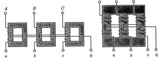
In the figure, the designation of phase voltages generated by the secondary windings of the transformer is indicated by the symbols UA, UB, and UC. From the phase windings to the load there are conductors that perform the function of linear wires. It is necessary to take into account the presence of voltage not only between the neutral and linear wires, but also between two linear conductors. This voltage is called linear and is designated UAC or UCA.
The line voltage value always exceeds the phase voltage. The difference between them is √3 times, since it represents the vector difference of the phase voltages. Thus, a three-phase power line allows you to receive not only 380 V, but also 220 V, depending on which circuit the load is connected to.
Structure
The authors propose to start considering a three-phase transformer with simplification. Readers are assumed to be familiar with 220 volt circuits. They know how a transformer works.
Brief description of the operation of a single-phase transformer
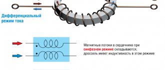
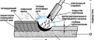
You need to start with a simple thing: the inductor coil creates a vortex magnetic field around itself. It stretches along the axis and comes out at the north pole. The figure shows two turns of wire. The current flows from plus to minus, the direction of the magnetic field strength lines is determined by the “gimlet” rule. The trajectory is bent, as a result of which the adjacent turn (the entire solenoid) is poorly covered.
It is required to transmit the magnetic flux as completely as possible, providing galvanic isolation (current). During transformation, the output voltage varies easily. Used when transmitting electricity to consumers.
Finally, a core made of a ferromagnetic alloy is capable of transporting the field to the secondary winding. Inside the material, the magnetic induction intensity increases many times over. Tight flux linkage is ensured, and the emf induced at the output becomes enormous. The field strength lines penetrate the core along the axis. The effect described above is obtained.
Three-phase transformer design
It’s easier to consider a three-phase transformer by imagining three single-phase ones. The screen shows a sample of the rod type. Like “armored” (the name belongs to the authors) it means: the windings are put on rods. They unite by closing the magnetic field lines with yokes. The word rod does not imply the presence of a circular cross-section. Probably present before, modern transformers practice other odds.
The core is made laminated and, by definition, is not round. Technologically difficult. Is a transformer equipped with a round core round? Yes, a turn enclosing a square is inferior in area to a round one of similar core length. It is an obvious fact that the material utilization rate of a modern transformer is alien to perfection. The core is rectangular, yoke, it is easier to arrange the charge plates.
It is recommended to represent a three-phase transformer with three rods, arranged side by side to form a single central unused rod.
Since the phases are shifted uniformly at an angle of 120 degrees relative to each other, the geometric sum of the vectors will be zero. If you assemble the cores of single-phase transformers, the magnetic flux will not flow through the central part. The basis is the operation of circuits with an isolated neutral. The middle rod does not carry magnetic flux, therefore, it can be thrown out of the structure. The remaining part is composed like this:
- The coils are located on parallel rods.
- The primary and secondary windings of the phases lie on a single rod.
- The core is closed by yokes.
- According to the symmetry of the phases, two designs are distinguished:
- Top view - equilateral triangle. Phase symmetry.
- Top view - single line. Phase asymmetry.
Phase symmetry means: the inputs are equal. If the rods are lined up in a row, the distance along the yoke between the outer ones is greater than between the other two pairs. The magnetic flux will become out of phase and the signal will be distorted. The core resistance is asymmetrical for the field. Causes current imbalance in idle mode. The effect is enhanced by poor quality assembly and poor saturation of the iron of the yoke.
Armored three-phase transformers are actually placed on top of each other, covered by a single single-phase core. There is no phase asymmetry, the primary and secondary windings lie on the same rod. Since the flux doubles at the central yokes, the cross-section of the core region must increase accordingly.
The primary winding is divided in half, covering the secondary on both sides, as shown in the figure (primary - I, secondary - II). Armored transformers have one undeniable advantage - low no-load currents. It is believed to be due to the short course of the field strength inside the core. There are three disadvantages:
- More weight with the same gear ratio, same power.
- The windings are difficult to repair because they are surrounded by armor on all sides.
- The cooling conditions are worse, although the volume is nominally larger. The core is heated during operation by magnetization reversal and relatively small eddy currents.
Cores
Laminated cores are assembled with sheets of steel. The thickness of the plates is smaller, the losses due to eddy currents will be lower, and the assembly is more painstaking. The layers are separated by a varnish coating for mutual insulation. Preventing the occurrence of eddy currents. The requirements for steel are quite typical:
- The high value of magnetic permeability ensures an increase in field induction tens of thousands of times. Therefore, the first necessary condition for the operation of a transformer.
- High resistivity is provided by silicon impurities (up to 4% by weight). As a result, losses are reduced to 50% for heavily doped samples.
- Low coercive force, causing low losses due to magnetization reversal (narrow hysteresis loop).
It has long been noted: the area of a square is 0.88 times the circumference. Consequently, the selected curve will be the most favorable. It is irrational to complicate the production process; in practice, they do things differently: low-power transformers are equipped with square rods, medium ones are equipped with cross-shaped ones (see figure), large ones are equipped with round ones. The end justifies the means; if substations stop saving energy, the losses will become enormous. The humble transistor receiver costs little. Savings – losses are small. The rectangular core provides the most favorable conditions for heat removal, since it is characterized by a large volume.
Sometimes dielectric inserts are placed in the corners to hold the winding along the desired curve. In oil transformers, the core is sometimes provided with slots. It is assumed that, circulating in the passages, the liquid will cool the winding and steel. Channels are equipped along the plates, across. The second case is more productive for a simple reason. The ends of the plates are not varnished, since Foucault currents (eddy currents) do not arise in the direction, the metal quickly releases heat distributed along the plate. The first method is easier to achieve from the point of view of the production process.
The wire does not fit well with the straight edge of the core, it bends outward, and the varnish insulation cracks at the corners. Places restrictions on the build process. During operation, thermal variations in geometric dimensions are inevitable, which aggravates these effects over time. Consequently, a rectangular coil has lower mechanical strength. Indeed, a round rod, due to thicker winding, increases the volume of the yoke; it is used due to frequent failures of powerful three-phase transformers of a different design.
Despite the advantages of designs with symmetrical phases, more often the rods are placed in a row for obvious reasons: the technological process is simplified. If the core is rod-shaped, the overlap assembly is used only for low-power samples; in other cases, the yoke is butted. For armored ones, on the contrary, low-power ones are close, others are overlapped.
Winding
In power transformers, the windings are concentric, located one inside the other, and have a common axis. Alternating windings are shown in the figure above; they are not produced for sale to the general public of radio amateurs. When calculating, attention is paid to calculating the following parameters:
- Mechanical strength (see above), including short circuit conditions.
- Electric strength of cores, insulation.
- Temperature operating conditions (including maximum).
The winding is made with round, rectangular (sometimes transposed) wire. The division of a single core into a number of cores is carried out, complementing the measure of core fusion. Will reduce Foucault currents. If the required wire diameter is more than 3.5 mm, replace it with a rectangular one (TK 16.K71 - 108 - 94). The gaps between the wires become too large. The round cross-section has the advantage of being easier to manufacture and more common in everyday use. Rectangular wire is mainly used for winding coils. Consequently, it is unprofitable to manufacture; the process is more expensive.
A rectangular conductor larger than 8x25 mm is transposed. The copper used for the winding is electrical grade, with a purity of at least 99.95%. Due to its high cost, it is often replaced with refined aluminum. The metal is characterized by lower tensile strength, lower ductility, and higher resistivity. The wire insulation is made from telephone and transformer paper. There is varnish:
- PBU, rectangular copper wire with transformer paper insulation.
- PB, rectangular copper wire with telephone paper insulation.
- PTBU, transposed copper wire with paper insulation.
- PTB, transposed copper wire with general paper insulation.
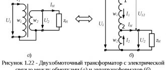
Operating principle of a three-phase transformer
As can be seen from the diagram above, instead of three single-phase devices, one three-phase transformer can be used. Its magnetic circuit consists of three rods, which are closed by yokes at the top and bottom. A primary and secondary winding is wound on each rod, then connected by a star or triangle. Each rod with windings is essentially a single-phase transformer. At the same time, it performs the function of a separate phase of a three-phase transformer.
Under the influence of the primary winding current, a magnetic flux appears in all rods. It is necessary to take into account the belonging of each such winding to one of the phases included in the three-phase system. Therefore, the currents flowing through these windings, as well as the applied voltages, are three-phase. Therefore, the generated magnetic fluxes are also three-phase.
Previously, it was believed that the movement of the magnetic flux occurs along a closed path, that is, passing along the rod, it returns to its beginning. In three-phase transformers there is no such return path; it is simply not necessary, provided the phase loads are the same. In addition, there is no need for a neutral star connection.
Types of winding
- The screw winding runs in a spiral with oil cooling channels. In power three-phase transformers they are used for low voltages. A spacer is placed between the layers.
- Continuous winding gets its name from its method: many windings are wound with one piece of copper wire. Often the outer coil is placed first, followed by relaying.
- The intertwined winding, due to the interlacing of adjacent turns, is characterized by high mechanical strength.
- The cylindrical layer winding resembles a screw winding; the turns are placed end-to-end without intermediate channels for cooling.
- The disk coil winding is similar to the continuous one, the difference is limited by the additional insulation applied separately for each coil. It has great mechanical strength.
A little history
Thanks to the English physicist Michael Faraday, in 1831, humanity became acquainted with electromagnetic induction. The great scientist was not destined to become the inventor of the transformer, since his experiments involved direct current. The prototype of the device can be considered the unusual induction coil of the Frenchman G. Ruhmkorff, which was presented to the scientific world in 1848.
In 1876, Russian electrical engineer P. N. Yablochkov patented an alternating current transformer with an open core. The device owes its modern appearance to the English brothers Hopkinson, as well as the Romanians K. Tsiperanovsky and O. Blati. With their help, the design acquired a closed magnetic circuit and has preserved the circuit to this day.
Types of magnetic cores
Safety precautions
During operation, certain rules must be observed:
- if cracks appear on the case, noise or vibration, the autotransformer is immediately turned off;
- It is prohibited to leave equipment for which continuous monitoring is provided unattended;
- you cannot connect a motor whose power is more than 70% greater than the power of the autotransformer;
- These devices must not be used openly, covered, covered with ventilation openings, or placed on them with other equipment or objects.
When carrying out repairs on an autotransformer or the device it is part of, it is necessary to disconnect it from the power supply.