Despite the variety of electrical equipment on the market, not in all situations it is possible to find a suitable converter unit to solve a specific problem. Therefore, many ordinary people try to make a transformer with their own hands to obtain certain operating parameters. It is worth noting that anyone can wind a transformer, even without specialized equipment and special skills, but this process is quite labor-intensive and painstaking. Therefore, initially you will have to decide on the type and characteristics of the device.
Selection of materials
Let's take a Russian wire, its insulation is stronger. The wire from old coils is used if there is no damage to the insulation. For insulation, paper or FUM film is suitable. For insulation between the windings, it is better to use varnish fabric and several layers of insulation. Cable paper and varnish fabric are suitable for surface external insulation. You can also wind the transformer using PVC electrical tape.
Impregnation is needed to increase operating time, but it increases the parasitic capacitance of the coil. Varnish is used for this purpose. For a simple transformer, you can use oil varnish. Each layer is covered. It is impossible to saturate all layers at once. The varnish should not dry quickly before winding is completed.
The frame is made of fiberglass or similar material.
Calculations of parameters of a homemade transformer
On a simple transformer the primary winding has 440 turns for 220 volts. It turns out 1 volt for every two turns. Formula for counting turns by voltage:
N = 40-60 / S, where S is the cross-sectional area of the core in cm2.
The constant 40-60 depends on the quality of the core metal.
Let's make a calculation for installing the windings on the magnetic circuit. In our case, the transformer has a window 53 mm in height and 19 mm in width. The frame will be textolite. Two cheeks at the bottom and top 53 - 1.5 x 2 = 50 mm, frame 19 - 1.5 = 17.5 mm, window size 50 x 17.5 mm.
We calculate the required diameter of the wires. The power of the transformer core with your own hands is 170 watts in size. On the network winding the current is 170 / 220 = 0.78 amperes. Current density is 2 amperes per mm2, standard wire diameter according to the table is 0.72 mm. The factory winding is made of 0.5 wire, the factory saved money on this.
- The winding of a simple high voltage transformer is 2.18 x 450 = 981 turns.
- Low voltage for filament 2.18 x 5 = 11 turns.
- Low voltage filament 2.18 x 6.3 = 14 turns.
Number of turns of the primary winding:
we take a wire of 0.35 mm, 50 / 0.39 x 0.9 = 115 turns per layer. Number of layers 981 / 115 = 8.5. It is not recommended to draw conclusions from the middle of the layer to ensure reliability.
Let's calculate the height of the frame with windings. Primary of eight layers with 0.74 mm wire, 0.1 mm insulation: 8 x (0.74 + 0.1) = 6.7 mm. It is better to shield the high-voltage winding from other windings to prevent high-frequency interference. In order to wind the transformer, we make a screen winding from one layer of 0.28 mm wire with two layers of insulation on each side: 0.1 x 2 + 0.28 = 0.1 x 2 = 0.32 mm.
The primary winding will take up space: 0.1 x 2 + 6.7 + 0.32 = 7.22 mm.
Step-up winding of 17 layers, thickness 0.39, insulation 0.1 mm: 17 x (0.39 + 0.1) = 6.8 mm. On top of the winding we make layers of insulation 0.1 mm.
It turns out: 6.8 + 2 x 0.1 = 7 mm. Height of the windings together: 7.22 + 7 = 14.22 mm. 3 mm left for filament windings.
You can calculate the internal resistance of the windings. To do this, the length of the turn is calculated, the length of the wire in the winding is taken, the resistance is determined, knowing the resistivity from the table for copper.
When calculating the resistance of the primary winding section, a difference of about 6 ohms is obtained. This resistance will give a voltage drop of 0.84 volts at a nominal current of 140 milliamps. To compensate for this voltage drop, we add two turns. Now during loading the sections are equal in voltage.
Marking
Marking is the first stage, which is carried out if materials and tools are available. Careful research is important to determine the technical specifications.
It is acceptable to do it manually using special tables (but note that in this case you will have to calculate everything yourself using formulas).
You can also select markup using programs - there are some available for free on the Internet. But in this case, a novice radio amateur will not be able to understand the calculation algorithm and learn how to perform the frame independently, without the use of computerized equipment.
How to do it manually
Testing of strength and fastening features is carried out experimentally. A coil is taken, or rather a sample of it, which you wouldn’t mind throwing away, and 10 turns are placed on it, which will be used for the main transformer.
A rod is selected with a diameter four times larger for wires with a thickness of 0.96 millimeters, five times larger if wires up to 1.56 millimeters are taken, and six times thicker if the wire thickness exceeds 2.44 millimeters. This must be taken into account; the selected instructions are available in special technical literature.
Separately, it should be taken into account that in addition to a certain bend, which certainly forms stronger in the first few layers, and then begins to round off, there is also a strong tension and stretching. When marking the frame, take into account that the multiplicity increases several times. For example, for a wire that is 1 millimeter thick, the radius of curvature will be about 5 millimeters. Radii for wires of any diameter are also placed in the corresponding tables.
Class selection
Carrying out markings according to samples allows you to avoid the appearance of loose and uneven surfaces in the winding. Thin getinax is used if it is necessary to increase the rigidity of the frame. For example, if the device power is up to 10 W, then the sizes of small parts will be 0.5, medium - 0.7 to 1.5, and large ones - from 1. Power up to 100 W implies the use of 0.7 - 1, 2, 0 - 4, 1 - 2 mm parts, respectively. For devices with power ratings from 100 to 500 W, take up to 1 to 2 mm for class a, from 3 to 6 for b, from 1.5 to 3 for class c.
For the latter type, with the highest power ratings, it is advisable to increase the radius of curvature by approaching the optimal rounding values. It is better to take special inserts made of material that is used for twisted magnetic wires. They are used if the thickness of the magnetic circuit is twice as thick as the working rod of the device.
Additionally, most of the protruding part of 3 millimeters is installed on the part. This is necessary so that the cheeks of the frame are firmly attached to the equipment. The sleeve is made slightly larger in size than the working rod by 0.5 mm, the gaps should not exceed this figure. Be sure to take into account whether the frame is obtained using hardware or whether it is supplied with the device.
Calculation using programs
There are several dozen programs on the Internet, most of them freely available, that calculate the transformer and its frame. In particular, the CARCASS program is popular, from version 1.0, 2.0 and onwards. It works online, but if you wish, you can download the file and install it on your computer. The program contains information about:
- core type;
- thickness of material and screed;
- core sizes A, B, C, N.
After entering all the information, press the “Enter” or “Calculate” button. The calculation will also appear on the coil line, which can be printed and applied to the available textolite. There is an option designed for a frame with a lock.
Making a transformer coil frame with your own hands
The angles on the parts and the accuracy in dimensions are important, which will affect the assembly of a simple transformer.
On the cheeks we allocate places for attaching the output contacts of the windings, and drill holes according to calculations. When the frame is assembled, now we round off the sharp edges that the winding wire will touch. We use a needle file for this purpose. The wires should not be bent sharply, as the insulation enamel will crack. Now let's check whether the plate is inserted into the frame window. It should not dangle or fit tightly. We put the frame on a special machine or get ready to wind the transformer by hand. Thick wires are always tossed around by hand.
\main\r.l. designs\ reference materials\…Manufacturing of ceramic inductor frame
Ted Garrott (GØLMJ) Radio Communication, August 2002, pp. 38…39
Ceramic products are made from clay by firing it at high temperatures, resulting in the product taking on the appearance of unglazed porcelain. Porcelain has properties that make it possible to use it in the electrical and electronic fields:
- products of any configuration can be produced;
- electrical characteristics are excellent, and at all frequencies;
- products have very low dielectric losses;
- products can be used at high temperatures without loss of strength.
Ceramic products are not used by radio amateurs (more precisely, their use is limited - UA9LAQ), since a product of the required shape is difficult to obtain, at least not in a store.
Since a kiln (muffle) was available to me, I decided to make my own coil for a symmetrical antenna tuner. This tuner was featured in the July and August 1998 issues of Radio Communication magazine.
Selecting a form to fill
To mold clay products, giving them different shapes, you can use various methods. After experimenting, I chose a method called “slip casting”, in which a plaster mold is filled with liquid clay. Porous gypsum removes excess moisture from the clay solution, while forming the surface of the product - a layer of clay in contact with the walls of the mold. Excess clay solution is removed from the mold, a product is formed that repeats the configuration of the model - inlays - hollow object. The mold, consisting of two halves, can now be separated and the clay model taken out. Let us describe this method in more detail.
Rice. 1
. Method for making a plaster mold. Plaster first pour – first pouring of plaster; Plaster second pour – second pouring of plaster; Model – model, mandrel; First stage (Section AA) – the first stage (part А-А); Second stage – second stage; Clay support – clay “support” of the solution at the first stage of pouring gypsum (see text); Clay seal – clay seal; View on B – B – view B – B
Mold making
The method of making a casting mold is shown in Fig. 1. The outer box is made of wood coated with plastic, the edges of the box are fastened with screws. The model (insert - prototype of the external configuration) of the ceramic product is supported in the box with pieces of clay, the surface of the dry clay, which is used in the first stage, is laid exactly at the level of the longitudinal centerline (central) line. This can be seen in photo Fig. 2.
Rice. 2
. Model - a cylindrical inlay is strengthened in a box-shaped box filled half with dry clay, the first half of the plaster mold can now be prepared by pouring gypsum.
The model should not be made of absorbent (absorbing) materials. I used a plastic (plastic) tube, sealing it with caulking on the ends that rest against the walls of the box, but you can also use wood, covering it with two layers of primer. In general, the model should be solid (not hollow), preventing plaster from getting inside it. A thin (made from the finest gypsum dust, well mixed, homogeneous) gypsum solution is poured on top of the model. When the plaster has hardened, the bottom of the box is opened and the dry clay is carefully removed. The entire plaster surface around the model (tube) is covered with three layers of soft (liquid) soap diluted with water in a ratio of 1:1, each time allowing to dry. Then, the entire structure is turned upside down and the remaining part is filled with plaster (see Fig. 1 for the sequence of operations). When the plaster hardens, the box is removed and the halves of the resulting plaster mold are separated. (See photo in Fig. 3).
Rice. 3
. Photo of a plaster mold consisting of two halves
Preparation of clay solution
I used clay intended for making porcelain, which is used in industry. The solution is prepared from dry powdered clay, water and a deflocculant (the deflocculant promotes the separation of clay particles - prevents them from caking, maintains the solution in a state of suspension, and creates, in fact, “liquid” clay).
Experiments have shown that a solution density of 33 ounces (1 ounce = 28.35 g) per pint (1 pint = 0.56824 L) is sufficient. The solution mentioned in the article was prepared from 21.67 ounces of dry powdered clay and 11.33 ounces of water, to which was added a deflocculant - 2.6 grams of sodium dispex (sodium bicarbonate). I figured that 1.25 pints of solution would be enough and increased the ingredients accordingly.
The supplied clay was rolled with a wooden (not glass bottle!) rolling pin into “pancakes” 4 mm thick and dried in a home oven at a temperature of 100 ° C. Then the clay was crushed and ground with a pestle in a mortar to a uniform fine powder. To avoid inhaling clay dust when grinding, you should use a gauze mask or a respirator. The clay initially supplied contains 22% water, so 1 unit of wet clay will only contain 0.78 units of dry mass. The deflocculant is added to warm water and mixed thoroughly in a plastic container. Clay powder is gradually added while stirring. To obtain a homogeneous mass, you need to use a (home kitchen) mixer. The solution is left for a day and mixed again. All components of the solution were weighed on a kitchen scale with a digital readout on liquid crystals.
Pouring the solution
The halves of the plaster mold are connected together and twisted with an elastic (rubber) tape. The mold is fixed on a wooden board covered with plastic, as shown in Fig. 4.
Rice. 4
. Clay deposition method (slip-casting). Liquid clay (slip) – liquid clay (solution); Clay forms on plaster - clay is deposited on plaster; Mold may now be split – the mold can now be removed; Mold filled with slip – a mold filled with clay mortar; Clay forms on mold walls - clay is deposited on the walls of the mold; Surplus slip poured off - excess solution is drained
A clay (plasticine, window putty) seal around the mold prevents the solution from leaking out. The mold is filled with the prepared clay solution and left alone for an hour. During this time, the mold must be covered with a lid. The liquid solution must be drained after an hour. At the same time, a hard layer of clay approximately 5 mm thick will remain on the inner surface of the mold.
After the clay leaves the mold, the bottom board is removed and the clay blank is carefully aligned along the edges with a sharp knife. The time for disassembling the mold halves is determined experimentally by the presence of a visible “lag” of the clay workpiece from the mold, otherwise the workpiece will be chipped and unsuitable for further use.
Drying a clay blank (tube)
This operation should be performed slowly, avoiding cracking and destruction of the workpiece. I did the drying for a week, and almost all this time there was a cap made of a plastic bag over the workpiece. During drying, you can trim the edges of the tube with a sharp knife. The tube will dry when its color is the same as a sample kiln-dried piece of clay.
Dry pipe clay is very fragile, crumbles, and generally requires careful handling. At this stage, I drilled all the holes necessary in the future frame and cut grooves for the turns of future coils. The grooves were cut using “Abrafile” sanding thread, which has a suitable diameter for 1.5mm wire. Cutting these grooves requires special care. The frame at this stage of manufacturing is shown in Fig. 5.
Rice. 5
. View of the clay frame before firing. All holes are drilled and guide grooves are sawn for laying wires in increments
Burning
The clay frame blank is fired in a kiln equipped with an electronic controller. The temperature in the oven rises 40 degrees per hour to approximately 600°C with the vents open. These conditions make it possible to remove chemically bound water and organic additives from the product by evaporation. The oven vents are then closed and the temperature quickly rises to 1210° C. The oven is turned off and waited until it cools naturally to 200 degrees, the oven lid is opened, and the finished frame can be removed from it as soon as it stops burning your hands.
Shrinkage
During drying and firing, the clay product “shrinks” and decreases in size. I found that during firing this decrease was 8%, and in total, during the drying-firing period, it was 12%. In the photo Fig. Figure 6 shows a finished assembly using a homemade ceramic frame.
Rice. 6
. Photo of a unit with a ceramic frame assembly
The connection pins are glued into the holes using Araldite glue. Making a frame using the “slip casting” method (precipitation of clay from a solution) is not the only one; there are a number of generally accepted methods. Anyone who decides to engage in such fishing should first familiarize themselves with the relevant literature.
Kilns
When making ceramic products, it is best to use a kiln that has a programmable electronic controller. My wife uses this oven to dry painted porcelain. After some negotiations, I managed to get permission to use the stove. Even a small stove of this class costs more than £500, so it makes sense to ask friends and colleagues for permission to use their existing stove for a small fee that covers the cost of electricity and moral damage...
Bibliography
In libraries and on sale you can find many books in the sections “Ceramics” and “Pottery”. I looked through a number of publications and bought myself the books “The Potters Manual” - by Kenneth Clark and “Slip-casting” - by Sasha Wardell.
Suppliers
Both of these books contained a list of suppliers who could send the clay used in the production of porcelain. (I don’t think that anyone would order clay from abroad, especially since there is a lot of their own white clay in the vastness of Russia; in order to exclude advertising, I am not providing a list of suppliers - UA9LAQ).
Free translation from English: Victor Besedin (UA9LAQ) Tyumen October, 2008
Winding a transformer with your own hands
We lay the first layer of insulation. Insert the end of the wire into the hole in the output terminal. We begin to wind the wire, not forgetting about its tension. You can check this way: the wound coil will not bend under your finger. The wire cannot be stretched, as the insulation will be damaged. It is recommended to soak the finished coil with paraffin so as not to damage the wire. If the winding hums while the transformer is operating, the wire insulation wears off, the wire bends and breaks. For this reason, the tension of the wire during winding is of great importance.
During winding, we move the coils closer to each other and compact them. The first layer is the most important.
There is no need to leave empty space on the layer. The highest voltage on the last turns is for the primary 60 + 60 / 2, 18 + 55 V. The varnish insulation will withstand the voltage; if the wire falls into the void of the layer, the insulation may be damaged. We saturate the first layer, then the second and so on. The insulation between the windings must be treated conscientiously. It must withstand up to 1000 volts. At the top of the insulation, it is recommended to write the number of turns and the size of the wire; this will be useful during repairs.
The layers of a homemade transformer must have the correct shape. As you wind the coil, it will bend at the edges. To do this, the layers need to be equalized during winding without damaging the insulation.
It is better to make forced wire joints on the edge of the frame behind the core. Connect the wire by twisting with soldering, overlay with soldering. The length of the contact when connecting is made more than 12 wire diameters. The joint must be insulated with paper or varnish cloth. Soldering must be without sharp corners.
The terminal ends of the windings are made in different ways. The main thing is to have reliability and quality.
Trial
To check the performance of U-shaped or toroidal transformers at home, you can use a conventional multimeter. To do this, switch the measuring device to the ringing mode and check the integrity of each of the windings. Then check the insulation between each winding and the magnetic core and the resistance between both windings. This is the simplest set of tests, which will give a general idea of the serviceability of a home-made unit.
To check the absence of short-circuited turns, a lamp is used that is connected in series to the primary winding.
In addition, electric machines are tested in idle and short circuit conditions. Such checks show how well the converter is assembled, but it is not necessary to perform them at home.
Completing the manufacture of the transformer with your own hands
We solder the lead ends of the windings, insulate the surface of a simple transformer, sign these characteristics on it and assemble the core. After this, you need to check this simple transformer with your own hands.
We measure the idle current of the homemade transformer; it should be minimal. Let's look at the heating. If the core heats up, then the iron is selected incorrectly. If the windings get hot, it means there is a short circuit. If it’s normal, then we short-circuit the secondary winding; there should be no crackling or strong buzzing.
An example of how to make a homemade transformer
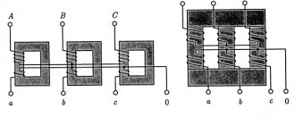
Let's move on to the manufacture of the transformer itself. Based on the finished core, we will calculate the power of the transformer, turns and wire, wind the primary and secondary windings, and assemble the transformer completely.
To wind a transformer with a voltage of 220 to 12 volts, we need to select a magnetic core. We select a W-shaped magnetic core and a frame from an old transformer. To determine the power supplied by a simple transformer, it is necessary to make a preliminary calculation.
Operating principle
The operation scheme of active inductors is based on the fact that each individual turn of the winding intersects with magnetic lines of force. This electrical element is necessary in order to extract electrical energy from a power source and convert it to store it in the form of an electric field. Accordingly, if the circuit current increases, then the magnetic field expands, but if it decreases, the field will invariably contract. These parameters also depend on frequency and voltage, but in general, the effect remains unchanged. Turning on the element produces a phase shift in current and voltage.
Photo - principle of operation
In addition, inductive (frame and frameless) coils have the property of self-induction, its calculation is made based on the data of the nominal network. In multilayer and single-layer windings, a voltage is created that is opposite to the voltage of the electric current. This is called EMF; the determination of electromotive magnetic force depends on inductance values. It can be calculated using Ohm's law. It is worth noting that regardless of the network voltage, the resistance in the inductor does not change.
Photo - connection of individual terminals of elements
The connection between inductance and the concept (change) of EMF can be found using the formula εc = - dФ/dt = - L*dI/dt, where ε is the value of self-induction EMF. And if the rate of change of electrical energy is equal to dI/dt = 1 A/c, then L = εc.
Video: calculating an inductor
Transformer calculation
We calculate the diameter of the primary winding wire. Transformer power P1 = 108 W:
P1 = U1 x I1
where: I1 – current in the primary winding;
then the current in the primary winding is:
I1 = P1 / U1 = 108 W / 220 V = 0.49 A.
Let's take I1 = 0.5 ampere.
From the table of wire diameter depending on the current, select the permissible current 0.56 A, diameter 0.6 mm.
You can wind a homemade transformer with your own hands without a machine. This will take two to three hours, no more. Let's prepare strips of paper to lay between the layers of wire. We cut out a strip with a width equal to the distance between the cheeks of the transformer coil plus a couple of millimeters so that the paper lies tightly and the turns do not overlap each other at the edges.
We make the length of the strip with a margin of two centimeters for gluing. Lightly cut along the edges of the strip with scissors so that the paper does not tear when bending.
Then we glue a strip of paper onto the frame, smoothing it tightly.
Winding the primary winding
Now we take the wire from an old coil, which has a wire with good, non-cracked insulation. We insert the end of the wire into a flexible tube of insulation from an old used wire of the appropriate suitable diameter. We insert the end of the winding into the hole in the coil frame (they are already present in the old frame).
The coil winds tightly, turn to turn. Having wound 3-4 turns, you need to press the turns against each other so that the winding of the turns is tight. To wind the transformer after winding the first layer, it is necessary to count the number of turns in the row. We got 73 turns. We make a gasket with a strip of paper. We wind the second layer. During winding, you need to keep the wire taut at all times so that the winding is tight. After the second layer we also make a paper gasket. If the length of the wire is not enough, then we connect another wire to it by soldering. We tin the varnished wire by heating the end with a soldering iron on an aspirin tablet. At the same time, the varnish is easily removed.
When the winding of the primary winding is completed, we insulate the end of the wire into a tube and bring it out to the outside of the coil. We make winding insulation between the primary and secondary windings. You can wind the transformer further.
Step-up transformer assembly
A feature of a step-up transformer is the larger cross-section of the cores of the primary winding of the transformer in relation to the secondary. A striking example is any unit that increases the supply voltage of 220 Volts to 400, 500, 1000 V, etc., accordingly, the insulation class of the transformer is selected according to the rating of the secondary winding, as in network transformers.
Please note that a large cross-sectional conductor cannot be wound with a homemade machine, since you will not be able to produce enough force. This is quite easy to determine - if the first turns move freely along the coil frame, or worse, you see a clear gap between the core and the frame, proceed to manual winding.
To assemble you will need to perform the following sequence of actions:
- Assemble the base from a dielectric material; to do this, you can cut it according to a cardboard pattern. The frame is assembled overlapping using glue.
Rice. 2: Make a frame for the transformer
If you have a ready-made sample, you can move on to the next step.
- Make holes in the cheek of the coil for the leads to the electrical network and to the consumer. Thread the conclusions through them.
Rice. 3: thread the primary winding lead - Place the first layer of insulation under the primary.
Rice. 4: Apply a layer of insulation to the coil - Wind the primary winding of the transformer - if thickness allows, use a machine, otherwise, do it by hand. When winding, every 4-5 turns, check the rigidity of the fixation and the tightness of the fit.
Rice. 5: wind the primary
If there are visible gaps, it is recommended to press down the coils with a wooden press die or nail them through the die with a hammer.
- Count the number of turns, it should correspond to the calculated one, insert the leads into the holes. Place a layer of insulation on the primary.
- After the insulation layer, wind the secondary, since a thinner wire will be used here; this procedure is easier to perform on the machine.
Rice. 6: wind the secondary winding
Periodically check the tightness of the turns and their fixation on the rod. A good fixation should not sag or deform when pressed with your fingers.
- If all the turns do not fit in one layer, they are laid out in several, then it is important to maintain the same number of turns in each of them. The layers are layered with dielectric material; note that the thickness of the insulation should not significantly affect the overall dimensions of the coils.
Rice. 7: Insulate the first layer - Bring the ends of the secondary winding to the cheek of the frame.
- Place the magnetic core in the window of the frame, the core is assembled alternately on each side, otherwise the losses will be too large. Then the core expands for tight fixation.
Rice. 8: Place the coils on the core
Powerful transformers with high voltage ratings are additionally impregnated with paraffin insulation. This procedure leads to increased capacitive losses, but creates additional protection against electric current.
DIY transformer assembly
To speed up assembly, we take two W-shaped plates. We insert them inside the frame alternately on both sides, two pieces at a time.
We are not installing the covering plates yet. They will be installed later. If you insert all the plates at once as a whole package, then gaps appear between the plates and the inductance of the entire core drops. After assembling the W-shaped plates of the homemade transformer, we insert the overlapping plates, also two pieces each.
After assembling the core, carefully tap its planes with a hammer to align the plates. Using racks and pins we will tighten the core. According to the rules, paper sleeves are put on the studs to reduce losses in the core.
We clean and tin the ends of the windings. Then we solder to the lead strips, which can be attached to the transformer frame. The result is a ready-made transformer with your own hands.
Write comments, additions to the article, maybe I missed something. Take a look at the site map, I will be glad if you find anything else useful on my site.