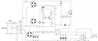
Almost two years have passed since I moved into our Data City. It's time to report on the work done. The first thing I want to talk about is the simplest transmotor. I decided to defeat the myth about the difficulties in winding transformers, both sound and power. The eyes are afraid, but the hands are doing!
It all started with such a simple machine for 7 rubles 20 kopecks, purchased back in the 80s of the last century.
Features of repair of commutator drives
This type of electric machine is more likely to experience mechanical failures.
For example, brushes worn out or commutator contacts clogged. In such situations, repairs come down to cleaning the contact mechanism or replacing graphite brushes. Testing the electrical part comes down to checking the resistance of the armature winding. In this case, the probes of the device are applied to two adjacent contacts (lamellas) of the collector, after taking readings, measurements are taken further in a circle.
The displayed resistance should be approximately the same (taking into account the instrument error). If a serious deviation is observed, then this indicates that there is an interturn short circuit or open circuit, therefore, rewinding is necessary.
Calculation of product parameters
Before winding a toroidal transformer at home, you will need to calculate its values. To do this you need to know the source data. These include: the output voltage, the outer and inner diameter of the core.
The power of the device is determined by the product of the areas S and Sо, multiplied by the coefficient: P=1.9* S * Sоk.
The cross-sectional area is calculated using the formula: S=h*(Dd)/2, where:
- S - cross-sectional area;
- h - height of the structure;
- D - outer diameter;
- d is the internal diameter.
To calculate the window area, the formula is used: Sok=3.14*d2/4.
The number of turns in the secondary winding is equal to the product W2=U2*50/Sok.
This calculation method can be applied to almost any type of toroidal transformer. But for the calculation of some products there is its own methodology.
Welding device
This type of transformer is characterized by a high output current. The maximum current and voltage are used as input parameters. For example, for a device with a welding current of 200 amperes and a voltage of 50 volts, the calculation is as follows:
1. The power of the transformer is calculated: P = 200 A * 50 V = 1000 W.
2. The window cross-section is calculated: Sok = π * d2/ 4 = 3.14 * 144 / 4 (cm2) ≈ 113 cm².
3. Cross-sectional area: Sc=h * H = 2 cm * 30 cm = 60 cm².
4. Core power: Рс = 2.76 * 113 * 60 (W) ≈ 18712.8 W.
5. Number of turns of the primary winding: W1 = 40 * 220 / 60 = 147 turns.
6. Number of turns for the secondary winding: W2 = 42 * 60 / 60 = 42 turns.
7. The area of the secondary wire is determined based on the highest operating current: Spr = 200 A / (8 A/mm2) ≈ 25 mm².
8. The area of the primary wire is calculated: S1 = 43 A / (8 A/mm2) ≈ 5.4 mm².
This calculation option is applicable not only for welders, but can also be successfully used for other types. As you can see, no difficulties should arise during the calculation.
Current transformer device
It is not difficult to make a current transformer with your own hands, but before making it you will need to perform a calculation. This calculation differs from the generally accepted one due to the design features of the product. It starts with the required value of the secondary current (unit ampere): Iam = Iper / Ivt, where:
• Iper - the value of the primary winding current, multiplied by the number of turns in it;
• Ivt - the number of turns in the secondary winding.
In order to figure out how to correctly perform the calculation, it is easier to consider a practical example of a homemade current device. Let it be necessary to obtain 4 volts at the output of the current device, and limit the current to 5 amperes.
The step-by-step calculation method looks like this:
- Take a ferrite ring, for example 20x12x6 from 2000hM.
- 100 turns of wire are wound. These turns constitute the secondary winding, since the primary is simply one turn of wire passed through ferrite.
- The value of the current in the secondary will be equal to: I/Ktr = 5 / 100 = 0.05 A. where Ktr is the transformation ratio of the transformer (the ratio of the number of primary windings to the secondary).
- The size of the load shunt is calculated according to Ohm's law: R = U/I. It turns out R= 4/0.05 = 80 Ohm.
In this way, calculations can be performed for any required parameters. Regardless of the shape of the current at the input, the voltage at the output of the current device is always bipolar. It is the resistance, not the diode, that is used as the secondary winding shunt. If there is a need for a diode, then a resistor is connected first, and then a diode or diode bridge. In the second case, the resistance is included in the diagonal of the bridge.
Winding machine operating method
A winding machine is a popular equipment with which transformer single-layer and multilayer cylindrical coils and all kinds of chokes are wound. The winding device evenly distributes the winding wire with a certain tension level. It can be manual or automatic, and works on the following principle:
How does the winding machine work?
- Rotation of the handle sets the winding of the wire or cable onto the coil frame. It serves as the base of the product and is put on a special shaft.
- The wire moves horizontally thanks to the guide element of the stacker.
- The number of turns is determined by special counters. In homemade designs, this role can be played by a bicycle speedometer or a magnetic reed switch sensor.
A mechanically driven winding machine allows you to perform complex winding:
- private;
- toroidal;
- cross.
Manual winding machine with mechanical revolution counter
It operates with the help of an electric motor, which drives the intermediate shaft using a belt drive and three-speed pulleys. The friction clutch plays a big role in this. Thanks to it, the machine operates smoothly, without shocks or wire breaks. A spindle with a fixed frame, on which a coil is placed, starts the counter. The winding machine is adjusted using a screw to any width of the reel frame.
Modern models are equipped with digital equipment. They work through a specially defined program that stores information in a storage device. The value of the length and diameter of the wire allows you to accurately determine the point of intersection of the lines.
Modern winding machines are equipped with special counters
§ 27. Winder of coils of transformers of the 1st category
Characteristics of the work . Winding coils with cylindrical copper windings of round and rectangular cross-section for transformers of various sizes on established winding machines under the guidance of a more highly qualified winder. Winding cylinders by laying wooden or metal slats around the circumference and tying them together.
Must know: the purpose and maintenance rules of winding machines; standard designs of transformer coils with non-layer and disk windings; name and marking of the insulating materials and copper used; purpose and rules for using the most common simple devices and instrumentation.
Components of a winding machine and its operating principle
The elements of the winding machine were assembled slowly. Almost everything was taken from old Soviet film equipment. Moving parts: handle, axle studs, guide roller - everything is equipped with bearings. Studs, nuts, washers and angles were purchased at a hardware store. I only had to spend money on studs, long nuts and angles. Otherwise, everything is made from available materials.
To accurately select the wire winding density, a set of several pulleys is threaded onto the stacker pin. So, in the case of loose winding, it was possible to move the belt one size and adjust the speed of rotation of the axes. During the process of winding the wire, the belt is twisted depending on the direction of the winding stroke according to the figure-of-eight shape or the direct position of the belt. You should make a couple of dozen test turns to correctly adjust the pulleys to the diameter of the wire.
A base is made from wood or other material in the shape of the inside of the transformer coil and is fixed to the stud with wing nuts. You can also make universal holding corners to secure the coil. A demonstration of the operation of the winding machine is shown in the video:
Professional ranks
The profession “Coil winder for transformers,” reviews of which are mostly positive, involves career development: the higher the qualification level, the higher the salary. On the path of professional development, a winder can reach 6 categories, each of which has its own features in terms of functionality and requirements.
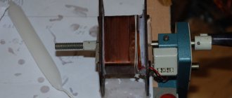
Do-it-yourself transformer winding machine
Very often, when creating electronic homemade products, you have to wind and rewind various transformers and coils. A good assistant in this difficult and painstaking task can be an easy-to-manufacture and reliable homemade winding machine for pulse transformers from computer power supplies and conventional transformers with a “W” shaped magnetic core. The design of the winding machine is very simple to manufacture, even a novice turner can do it. The machine consists of a shaft mounted on a rotation support. On the right side there is a handle for rotating the shaft. On the shaft from left to right there is a clamping device, left and right cones for reliable fastening of transformers.
This picture shows a drawing for making a winding machine with your own hands. The machine is designed for winding pulse transformers from computer power supplies and “W” shaped transformers. If you are going to wind something very small or too large then you need to scale the drawing to suit your needs. Well, if you are satisfied with the size of the machine, feel free to take the drawing and go to a familiar turner. - A good turner will make a winding machine in three hours... - Let him do it. Oh, and don't forget to bring some currency lathe with you. All work must be paid.
Drawing of a winding machine for winding pulse transformers
The machine is equipped with an electronic revolution counter. Which I purchased from a very famous Chinese online store for only $7.5. Perhaps it’s not expensive... For this money, the meter is equipped with a reed switch sensor, a mounting plate for the reed switch sensor and a small neodymium magnet! There are two oval buttons on the front panel of the meter. The left “Pause” button turns on the device and saves the meter readings, the “Reset” button resets the device readings. The device is powered by just one 1.5V AA AA battery, located on the rear panel of the revolution counter under a plastic cover. There are also connectors for connecting a reed sensor and an additional “Reset” button. Read the review of the revolution counter in this article.
I screwed the reed sensor to the aluminum stand using a mounting plate. A neodymium magnet was attached to the handle. For proper operation of the device, it is necessary to establish a gap between the reed sensor and the neodymium magnet of no more than five millimeters. Each passage of the neodymium magnet over the reed sensor is counted by the revolution counter as one turn.
How to use a transformer winding machine?
And so, a turner I knew made all the parts of the machine in three hours. You assembled the winding machine with your own hands, carefully lubricated all the rotating parts, and installed a winding counter. Now you can start winding the transformers. Unscrew the M5 screw on the clamping device, remove it and the left clamping cone. We put the transformer frame on the shaft and put on the left cone with a clamping device. Use a flat screwdriver to fix the M5 screw on the clamping device, then tighten the frame with two nuts. In this case, the main thing is not to overtighten, otherwise you will split the frame. We turn on the turns counter and, if necessary, reset the device readings to zero.
We clean the end of the wire from the varnish with a knife and screw it to the frame stamp from the transformer. We guide the wire with our left hand, and rotate the handle with our right hand. After a few minutes of training, the wire will lie in even layers. To avoid breakdown, each layer of wire is insulated with several layers of ordinary tape. Don't forget to watch the meter readings.
Friends, I wish you good luck and good mood! See you in new articles!
↑ Algorithm of my program
I will describe the algorithm of the program as I saw it for myself. We turn on the controller and the seven-segment indicator shows “0.00” zeros. Using the “+1” and “-1” buttons, set the value of the wire diameter (for example, 0.31) and press the “START” button. The controller, based on the above constant “A = 0.02”, recalculates how many pulses it needs to send to the stepper motor driver to move it a distance of 0.31 mm. Those. 0.31/0.02 = 15.5 pulses. Since the number of pulses must be an integer, the controller produces 16 pulses (or 15). There is an error, where without it.
We press the “START” button, a small square lights up on the very first indicator and the program moves to the next stage of work, where the controller waits for a signal from the sensor, which will be on the axis with the coil, to allow it to issue a packet of pulses for the stepper motor. Here he receives an impulse and the MK issues a packet of impulses. The wire layer carriage moves and waits for the next enable pulse.
If during the work you need to “adjust” the diameter of the wire and return to the first part of the program
, you need to press “START”, the square will disappear and you can change the value of the wire diameter. One note: in order for the controller to respond to the “START” button, the sensor disk on the main axis must be on the black segment, i.e. the controller must receive a “log” level from the sensor. 1".
I haven’t learned how to work with interruptions yet and did the best I can. I drew the sensor disk into 4 parts and painted the opposite segments with black varnish, in a checkerboard pattern. Since there will be 2 black sectors on the disk, the controller will respond to every 180 degrees of rotation of the axis, and accordingly will move the carriage by ½ of the wire diameter for every 180 degrees. In this case, the minimum winding pitch (in my case) = 0.04 mm. The program runs under an internal clock with a frequency of 1 MHz.
Operating principle of the machine
It is not difficult to work on the designed machine. The technological process requires certain actions:
- The upper shaft is prepared for work: the pulley is removed, the required length of the coil frame is set, and the right and left disks are installed.
- A fastener is inserted into the hole in the upper shaft, centered and the frame is clamped with a special nut.
- The required pulley for the primary winding is mounted on the feed shaft.
- A stacker is installed opposite the reel frame.
- The belt is placed on the pulleys in a ring or figure eight, depending on the type of installation.
- The metal wire is inserted under the additional shaft, placed in the groove, and secured.
- The wire tension is adjusted using clamps located at the top of the stacker.
- The wire should be wound tightly around the base of the coil.
- The numerical value “1+1” is recorded on the calculator.
- Each revolution of the shaft adds a given count.
- If the turns need to be rewinded, press “–1” on the computing device.
- When the wire reaches the opposite part of the frame, use a collet clamp to change the position of the belt.
For different thicknesses of metal wire, the pulley is correlated with the winding pitch.
Professional characteristics
In addition to professional knowledge, a winder of coils installed in electrical equipment must also have a number of other qualities. On which the quality of his work will depend.
The required professional traits include the following:
- Physical training. Working at a machine involves being on your feet for a long time, and some types of work involve lifting heavy objects.
- Coordination of movements. A necessary condition for fast work on the process.
- Concentration. If you are absent-minded, there is a risk of missing a technological step or performing an operation incorrectly, which is fraught with serious consequences.
- Visual memory. The coil is created according to the technical map, so it is important to remember the location of the parts, their size and quantity.
Manufacturing of turns counter
To determine the number of wound turns on the machine, a special counter is needed. In a homemade machine, the device is made like this:
Counter for winding machine - diagram
- An electromagnet is attached to the upper shaft.
- The sealed contact is located on one of the sidewalls.
- The output contacts of the reed switch are connected to the calculator in the place where the “=” button is located.
- The coil with the wire is placed separately - on another shaft with levers that lift the device up and fold it inside the machine.
Thanks to these elements, the equipment becomes compact and does not take up much space.
What is a transformer winding machine?
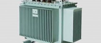
Walking through any populated area, everyone has more than once noticed large iron booths with many wires sticking out of them, and everyone knows that this is a transformer. The quality of electrical energy, the stability of its receipt and the prevention of the risk of short circuits depend on the operation of this mechanism - special elements are responsible for this, the creation of which is the responsibility of the winder. If you understand what kind of work a transformer coil winder does, you can come to the conclusion that these are “invisible” suppliers of safe and high-quality electricity.
The device of a homemade winding machine
In industrial settings, special fixtures are used to mass produce various types of electrical coils and transformers. The production of similar products allows you to invest financial resources in high-speed, automatic equipment to increase the number of products produced.
When working with your own hands when repairing, restoring, creating new coils or transformers, there is no need to fully automate the rewinding process, but the method of manually laying each turn of wire does not suit all craftsmen. Therefore, the practice of creating your own models arose.
The simplest option is a do-it-yourself manual winding machine, which is equipped with an adjustable stacker and a winding counter.
When creating it, you should pay attention to only a few conditional requirements:
- simplicity of design;
- use of improvised materials;
- possibility of winding coils of different sizes and configurations.
The device of the simplest homemade winding machine for transformers
An example of such a machine made by hand is this design, which works on the principle of a well gate:
- base with two vertical posts made of wood or plywood;
- a horizontal axis mounted on stands made of thick wire, one end of which is curved in the shape of a handle for rotation;
- two tubes mounted on the axle, on one of which there is a wooden block, which is fixed with a metal pin and has a wedge for reliable fixation on the rotating axle;
- a coil counter (bicycle odometer), which is connected to the free end of the axle through a dense rubber tube or a coiled spring of a suitable cross-section.
The principle of operation of such a device is based on placing the transformer frame on the axis of the device, and rotating the gate with your own hands with manual control of the density of the wire laying and visual control by counting the turns. to menu
Winding of toroidal transformers
The widespread use of toroidal transformers in household appliances and devices providing low-voltage lighting creates the need for a machine, or rather, a device that will help wind wire on a frame of a round closed shape.
In industrial conditions, special ring machines are used for high-quality winding of toroidal transformers. At home, you have to wind it by hand for a long time and without a guarantee of high-quality, even laying of the wire.
A device in the form of a shuttle, which works on the principle of a sewing needle, somewhat facilitates the work of winding toroidal transformers, but not to an sufficient extent.
Winding machine for toroidal transformers
To create a more productive device for winding toroidal transformers, you will need a bicycle wheel rim. It is secured to the wall with a pin and has a rubber ring to secure the wire.
Since the rim is solid, in order to put the frames of toroidal transformers on it, it will need to be cut and then fastened with collapsible plates.
Winding toroidal coils using this device occurs as follows:
- a reel prepared for winding is put on the disconnected rim;
- the rim is fastened (connected) with plates so that it is a solid circle;
- wind the required amount of wire around it;
- connect the end of the wire to a coil freely moving along the rim;
- They begin to move the coil along the rim in complete circles, due to which the wire itself is laid on the transformer frame.
When performing such almost manual winding, it is necessary to monitor the wire tension and the density of the turns.
data-ad-client=»ca-pub-8514915293567855″ data-ad-slot=»5929285318″>
The bicycle wheel rim is only suitable for large reels. The same winding principle can be applied for small toroidal transformers using any flat ring of suitable dimensions. to menu
This is interesting: Hydraulic pipe benders - types, videos, photos
Functions and knowledge
The ratio of the number of functions performed and the required knowledge according to qualifications
| Category | Professional Responsibilities | Required knowledge |
| 1 |
|
|
| 2 |
|
|
| 3 |
|
|
| 4 |
|
|
| 5 |
|
|
| 6 |
|
|
Winding machine on Arduino
Sometimes in amateur radio practice it becomes necessary to wind a large number of turns of wire to create transformers, chokes, coils and similar winding products. If we are talking about a hundred turns there are no special problems; it is wound using simple mechanical devices. But when you need to wind several thousand turns, and even turn after turn, then you think about automating this very tedious process.
The device in question is an automatic winding machine with a winding stacker and a process indication on a symbolic LCD screen. The intelligent core of the device is the familiar ATmega328P microcontroller, located on the Chinese version of the Arduino UNO board. The controller, through a CNC Shield (CNC expansion board), controls the power part of the device, consisting of two stepper motor drivers (SM) based on the DRV8825 chip and two stepper motors 17HS3401 and 17HS4401 (full revolution 200 steps). The HMI consists of a KY-040 rotary encoder module and a 16x2 character display with an HD44780 controller and an I2C bus communication module on a PCF8574A port expander. The circuit receives power from a 220AC-12DC 60W switching power supply.
The microcontroller uses drivers “Z” and “A”; on the CNC Shield, to connect driver “A” to pins 12 and 13 of the Arduino, jumpers D12-A.STP and D13-A.DIR must be installed. We select the DRV8825 operating mode with a microstep of 1/16 by installing jumpers M2 on the board, this means that for one step of the SD (1.8°) it is necessary to apply 16 edges of the STP signal. The installation of DRV8825 modules must be done as shown below.
After installing the SD drivers, it is necessary to set the current limit. When a 12V voltage is connected to the CNC Shield board, but without electric motors, you need to rotate the trimming resistor to set the limit values. We control the current value with a multimeter and by rotating the trimmer with a screwdriver, we achieve voltage values for driver “Z” of 0.68V and 0.52V for driver “A”. These values are directly related to the rated current of the motor. For 17HS4401 In = 1.7A, and for 17HS3401 In = 1.3A. The voltage value in a mode that is gentle for the motor is calculated using the formula Vref = 0.8*(In / 2).
We connect the I2C 1602 LCD to the corresponding pins SCL, SDA, 5V, GND of the expansion board. On the encoder module we add a pull-up resistor R1 10k if it is not there. To eliminate contact bounce, it is necessary to assemble a hardware suppression circuit; it can be designed as a module that complements the KY-040 module as shown below. Low-pass filters on R4-6 and C1-3 eliminate bounce, and Schmitt triggers MC 74НС14N restore the leading and falling edges of the signal.
To connect the encoder to the Arduino, we connect pins X.STEP and CLK, Y.STEP and SW, X.DIR and DT as well as GND and +5V with the corresponding pins of the board.
The mechanical part of the winding machine consists of six racks screwed to plexiglass. The stands are printed with plastic on a 3D printer, but if they have the proper straightness, they can be made in other ways and from other materials. The main shaft (M6 pin) is driven by SD 4401 and the winding frame is located on it. Next are two stacker stands with a shaft with a diameter of 6 mm and an M4 pin (thread pitch 0.7 mm) on the SD 3401 shaft. Rotation of the motor leads to linear movement of the stacker, while one step of the SD gives movement L = thread pitch / steps per revolution = 0.7 /200 = 0.0035mm. The last two posts hold the feed reel. Pressing the rubber washer against the bearing ensures tension in the wire during winding.
The program for ATmega328P is written in the Arduino IDE development environment in C++. To successfully compile the code, you must have the LiquidCrystal_I2C library installed.
From the main menu you can get to the submenu for controlling the position of stepper motors POS CONTROL; this is necessary to set the initial position of the main shaft and stacker. The AUTOWINDING submenu is for entering automatic winding values. Work with the encoder button, as well as with the encoder itself and the stepper motor drivers, is carried out through interrupts.