A stripping and grinding machine is a special device that provides stripping and cleaning of castings in industrial conditions. In home workshops, such devices are practically not used. They remove excess layer from metal workpieces: rolling, stamping. In this case, the formation of products does not occur.
The effectiveness of how the grinder will work depends on the speed of rotation of the grinding wheel. It is also important to choose the correct force for the impact of the abrasive material. There are different types of devices presented, but you need to choose them correctly, taking into account many factors.
3M636 Roughing and grinding machine with two wheels on a stand. Purpose, scope
3M636 roughing and grinding machine is designed for cleaning and roughing castings in a production workshop, as well as for performing metalwork work - removing burrs, chamfers, peeling sprues, for sharpening metal-cutting woodworking and other tools (drills, cutters, knives).
When using appropriate tools, they can be used for grinding and polishing parts.
General layout of the 3M636 grinding machine
For stripping (cleaning) cast iron and steel castings, medium-hard (ST2) and hard (T) wheels with a grain size of 20 and 24 units are used.
3M636 type roughing and grinding machine complies with the “H” standard - this means that this equipment is excellent for finishing work.
3M636 machine is equipped with two 600 mm grinding wheels with a width of 75 mm, which are driven by a powerful 11 kW motor.
The rotation speed of grinding wheels ranges from 955-1500 rpm. In this case, the distance between the centers of the circles is 1025 mm.
3M636 roughing and grinding machine is capable of processing fairly large products - the maximum workpiece weight is 30 kg.
For operator convenience, the machine is equipped with a small work table 110 x 200 mm.
Grinding wheel type PP according to GOST 2424-83, GOST R 52781-2007, GOST R 52588-2011 on a ceramic bond.
3M636 machine is manufactured in accordance with the requirements of TU 3813-084-00210757-2016 “Roughing and grinding machine”.
Location of the main components of the 3M636 roughing and grinding machine
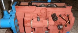
Photo of the 3M636 roughing and grinding machine
Photo of the 3M636 roughing and grinding machine
Photo of the 3M636 roughing and grinding machine
Device classification
There are different designs of grinding machines on the market. There are three main groups of devices.
Stationary - such units are used for processing small workpieces.
The stationary grinding machine is
But grinding on the market is available one-sided and two-sided. This group includes a radial sharpening device - it is more popular because it performs many functions, a trimming device. Stationary equipment is equipped with grinding wheels, the diameter of which ranges from 40–75 cm.
Suspended units - with its help medium and large workpieces are processed. The device does not stand on the floor, but is suspended. It is more convenient, since it can be turned in any direction; such manipulation makes the grinding of parts better. In addition, working with a suspended device is physically easier. It is equipped with a larger abrasive wheel and also has higher power.
Special – these include semi-automatic and automatic units. More often they are used in mass production of blanks. Fully automated devices can do without direct human intervention. They are more productive, you just need to set the appropriate settings.
Today, the industry produces mobile machines that are more convenient to use and help increase productivity.
Mobile grinding machine
But the better the casting of the part, the less effort will be required to polish it.
Composition of the 3M636 roughing and grinding machine
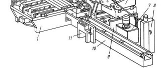
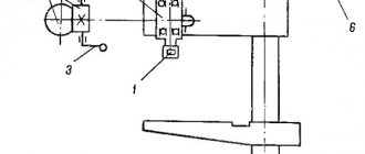
The components of the 3M636 are shown in Figure 1.
On the upper part of the machine body 1 there are bearing housings 2 and a protective casing 8 with handles. The bearings support the shaft 12 on which the drive pulley 11 is mounted. The pulley 11 has the ability to move axially along the drive shaft 12 of the machine. Rotation of the pulley 11 is transmitted by V-belts from an electric motor located inside the housing 1 and mounted on the plate 10.
Auxiliary installation movements of the electric motor are carried out along the horizontal grooves of the plate 10. The belt tension can be adjusted using the vertical grooves of the plate 10.
Protective casings 4 with outlet pipes 9 are attached to the bearing housings 2. Grinding wheels 5 are attached to the shaft 12 inside the casings 4.
The brackets 3 are supports for the handholds 7, which can be installed at the height required by the operator. The presence of grooves in the hand rests 7 allows you to move them to the desired position.
Protective transparent screens 16 are installed on the brackets 15. The machine operates only with the protective screens 16 lowered.
Kinematic diagram of surface grinding machine 3B722
Kinematic diagram of surface grinding machine 3B722
Vertical feed chain of the grinding headstock
Manual feed. The movement from flywheel 35 is transmitted through gears 23, 22, clutch 21, bevel gear pair 20, 19 to nut 18 connected to lead screw IX..
Since the nut is fixed against vertical movement, when it rotates, screw IX will move in the axial direction and move the carriage with the grinding headstock.
Automatic feeding. At the moment of reversing the grinding head, oil is supplied to one or another cavity of the cylinder of the feed mechanism 46 and moves the plunger rack 47. The latter, through the gear 48, rotates the crank 45, which, through the connecting rod 44, turns the lever 43 with the pawl 37 sitting on it at an angle of 40-50° .
The pawl turns the ratchet 25 connected to the flywheel 35. The movement is then transmitted along the chain described above to the screw.
The amount of automatic feed is adjusted by turning the cover 24, as a result of which the pawl 37 can turn the ratchet 25 along the entire path of its movement or part of it. The position of the cover 24 is changed from the handle 30 through gears 28, 27, 29, 26 and a gear sector cut on the cover 24.
To automatically stop the feed after removing the set allowance, a sector 31, 88 mounted on the limb 36 is used. At the same time, it enters the rolling zone of the pawl 37, which begins to slide along it without touching the teeth of the ratchet 25.
When working manually, a hard stop 38 is brought to the “hard stop” by the handle 39, against which at the end of the stroke the stop mounted on the dial 32 rests. The dial is connected to the flywheel 35 by means of a gear lock 33, which is activated by pressing the button 34.
Accelerated movement. An accelerated installation movement is prepared by turning the handle 41. In this case, using a helical groove on the shaft using a lever 49, gear 22 is disengaged from gear 23 and flywheel 35 is disconnected from the feed chain. At the same time, the cam 40 presses the limit switch 42, which unlocks the push-button station for starting the electric motor of the rapid movement mechanism.
When the electric motor is turned on, the movement from the electric motor shaft is transmitted by a silent chain through sprockets 52, 53. Gears 50, 51 to screw IX along the previously discussed chain.
In this case, the grinding head moves up or down.
Grinding headstock cross feed chain
Manual feed. From flywheel 12 through a worm gear (worm 5 - gear 4), rotation is transmitted to rack and pinion gear 2, which is meshed with rack I mounted on the grinding headstock.
To prevent the transmission from breaking when the grinding head is hydraulically moved from the cylinder, worm 5 is disengaged from gear 4 by turning handle II. In this case, the eccentric sleeve is blocked by cam 6 and lever 3, excluding the movement of the grinding head from the hydraulic cylinder when the worm is turned on.
Automatic feeding. When the grinding headstock moves transversely from the hydraulic cylinder, pin 17, mounted on the headstock body, slides along the spiral groove of shaft III, causing it to rotate. Next, through gears 16 and 15, a disk with adjustable stops 13 is driven into rotation. The disk with stops makes almost a full revolution at the maximum transverse passage of the grinding headstock, and the stops, acting on the reversible handle 14, rotate it together with the roller and the lever 9 sitting on it. The lever with one of its fingers acts (when reversing the grinding headstock) alternately on the limit switches 7 and 10, which give the command for vertical automatic feed, and with the other finger it switches lever 8, connected to the reversing spool of the grinding headstock reverse hydraulic box.
Handle 14 can also be used to manually reverse the grinding headstock.
Grinding head drive. The grinding wheel spindle receives rotational motion through a coupling from a flange-mounted electric motor with a power of 10 kW at 1460 rpm.
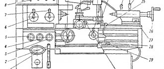
Electrical equipment of the 3M636 machine
The electrical circuit diagram is given in Appendix A.
The electrical equipment of the machine consists of:
- electric motor AIR132M4 380 V IM1081, operating in three-phase mode;
- input machine;
- electromagnetic starter;
- START buttons;
- STOP buttons;
- two limit switches;
- lighting lamps.
The cross-section of the supply wires is at least 1.0 mm² (copper) or 2.5 mm² (aluminum).
Electrical equipment is protected from overload by an electrothermal relay.
The electrical components of the machine are located in cabinet 14. The machine control buttons are located on panel 13.
Unit design
The equipment consists of the following components and parts:
- power electric motor 380 V,
- floor stand – 358 kg,
- start and stop control buttons,
- two abrasive wheels and their protection,
- protective casing for the housing,
- lighting elements.
Main mechanisms of the unit:
- rotor,
- starter.
A modern 3K634 machine has a main unit responsible for the rotation of roughening, grinding and grinding wheels - a head with a two-speed electric motor. The housing with two covers houses the rotor, fan, stator and motor shaft; it replaces the spindle.
The fan is protected by a special casing to ensure safe operation; the cover is hinged to facilitate repairs or access to the object.
Since the engine heats up during operation, the manufacturer provides a fan that effectively cools it with circulating air flows inside the head and frame.
Operating restrictions
Persons operating the machine must know its design, operating rules within the scope of this manual and safety requirements.
It is not allowed to operate the machine if it is mechanically faulty, if the grounding is damaged, or if there are no protective covers or safety devices.
Only persons of the appropriate profession, specialty and qualifications who have undergone instruction and training should be allowed to operate the machine.
The deflection of V-belt drive belts should be within 25-30 mm, when pressing the belt with a force of 70-90 N.
Before installation on the machine, new grinding wheels must be tested for compliance with the requirements of GOST 2424 “Grinding wheels. Technical conditions" and GOST R 52588 "Abrasive tools. Safety requirements".
It is prohibited to use grinding wheels with cracks on the surface, as well as those without a mechanical strength test mark or with an expired shelf life.
Before installing new grinding wheels on the machine, it is necessary to test them on a bench.
Installation of grinding wheels should only be carried out by specially designated and instructed workers. The fastening flange screws should be tightened sequentially in pairs using a normal-length wrench. The gap between the circle and the lower edge of bracket 15 should be no more than 6 mm.
You can start working on the newly installed circle only after a 5-minute test at idle speed.
It is forbidden to slow down the rotating circle by pressing on it with any object.
It is prohibited to reinstall the hand rests 7 (Figure 1) while the machine is operating.
The machine and the devices included in its composition must have reliable grounding. The quality of grounding is checked by external inspection and measuring the resistance between the metal parts of the machine and the grounding clamp at the input to the machine. Grounding resistance is no more than 0.1 Ohm.
Preparing the machine for use
Before operating the machine, check:
- serviceability and completeness of the machine;
- serviceability of grounding, supply cable and plug;
- reliability of fastening of grinding wheels, protective covers and supports;
- serviceability of the dust collector exhaust device.
Handles 7 should be installed so that the upper point of contact of the workpiece with the grinding wheel 5 (Figure 1) is above the horizontal plane passing through the center of the circle, but not more than 10 mm. The gap between the edge of the tool rest and the grinding wheel should be less than half the thickness of the work being sanded, but not more than 3 mm.
Hand rests 7 must be securely fastened. Rearrange the tool rests only when the machine is stopped.
Using the machine
Use the input switch to supply voltage to the machine. By pressing the START button (icon ▌ in Figure 4), turn on the machine’s electric motor.
When starting and stopping the machine, resonance may occur, which causes short-term vibrations. The permissible vibration velocity on hand rests 7 is no more than 2.0 mm/s.
Check the operation of the machine at idle speed for 5 minutes, paying attention to the direction of rotation of the grinding wheels.
Setting up the machine when sharpening cutters
Sharpening cutters on back surfaces
When sharpening cutters along the rear surfaces, it is necessary to loosen the screw securing the support in the curved guides and set the rear angle along the dial, tighten the screw securing the support (Fig. 14. a).
Set the protractor at an angle of 90° - φ (φ is the main angle in the plan) or φ1 (auxiliary angle in the plan) (Fig. 14, b, c, d) and secure the protractor so that the middle of the sharpened edge coincides with the middle of the diamond ring circle. It is necessary to ensure that the length of the section where the cutter rests on the protractor bar is as long as possible. After this, the assistant is given a rocking motion (oscillation). The amount of oscillation is set by the stops of the oscillating tool rest.
The cutter should not be allowed to come off the diamond ring of the grinding wheel.
The set of accessories includes devices for sharpening the back surfaces with a cutter clamp and a protractor without a clamping device. When working without a clamp, the cutter is fed to the wheel by moving the cutter along the support bar of the protractor; when working with a clamp, the flywheel is rotated. It should be borne in mind that at angles φ and 90° - φ less than 45°, it is better to use a device with a cutter clamp.
Sharpening cutters along the radius
The radius is sharpened manually, and oscillation of the table is not required.
When sharpening straight cutters along the front surface, the work is carried out in a device for sharpening the rear surfaces with a mechanical clamp (Fig. 14, e), but the cutter must be laid on the table with the side plane of the holder and the base of the holder pressed against the reference ruler of the dial.
The required front angle of the cutter is set using the protractor, and the inclination angle is determined using the tilt dial of the tool rest.
Sharpening is done by oscillating the tool rest, and feeding is done by rotating the cross-feed handwheel.
Sharpening bent cutters along the front surface
When a device for sharpening the front surfaces is installed on the tool rest, it is an inclined tool rest (Fig. 14, e).
The device is fixed at an angle. A device for sharpening the rear surfaces is secured in the groove of the tool rest, aligning the “0” of the protractor with the edge of the groove. The rest of the settings and work are carried out in the same way as when sharpening straight cutters on the front surface. The creation of thresholds on the front surface of the cutter is similar. The circle for this purpose must be profiled according to the shape of the transition part of the sill.
Finishing of cutters
The finishing of the cutters is carried out with a finishing diamond wheel in the same way as sharpening. Recommended modes when working with coolant - transverse feed for 10 double strokes of the table, mm:
- pre-sharpening: 0.1..0.2
- finishing sharpening: 0.03..0.06
- finishing: 0.01..0.02
Longitudinal feed is independent, carried out by springs within the range of 1..4 m/min.
When feeding manually, there should be a cutter pressure on the wheel of 7..12 kgf/cm2 (when sharpening a cutter with a sharpening strip of 10 x 2 mm, the pressing force is 2..2.5 kgf).
Cooling
Grinding, sharpening and finishing with diamond wheels should be done with cooling.
The use of coolant during the grinding process increases the durability of diamond wheels and reduces the wear rate of diamond grains.
The coolant reduces the heating temperature of the workpiece (tool) and reduces local stresses that can lead to cracks and chips. In addition, the coolant removes grinding waste from the working surface of the wheel, which helps to significantly reduce the “greasing” of the wheel surface, increase the cleanliness of the machined surface by one or two classes, increase productivity by 25..30% and reduce the wear rate of the wheel by up to 50%.
When using metal-bonded wheels, cooling is mandatory (except for shaped finishing) and must be continuous. Coolant should be supplied in an amount of 2 - 3 l/min. Organic bonded wheels can be used without cooling,
Coolant splash protection
The protective casing of diamond wheels is made with a reversible flap, and a disk is placed in the circle to prevent intense splashing of coolant.
It is necessary to ensure that the damper, when working with cooling, completely covers the non-working area of the grinding wheel.
To protect against the jet of coolant knocked off by the cutter, there is one shield with a permanent magnet on each side of the machine, mounted on the tool rest or on the cutter holder. In addition, shields installed on the edge of the trough prevent splashes from hitting the floor of a working machine and provide protection for the worker.
Technical characteristics of the 3M636 grinding machine
| Parameter name | 3M636 | TSh-4.01 (Stankograd) | TS-4 (Stankograd) | TS-4 (Orsha) |
| Basic machine parameters | ||||
| Number of grinding wheels | 2 | 2 | 2 | 2 |
| The largest outer diameter of the circle, mm | 600 | 600 | 400 | 400 |
| Maximum height (width) of the circle, mm | 80 | 50 | 50 | 50 |
| Wheel diameter, mm | 203 | 203 | 203 | 203 |
| Diameter of worn circle, mm | — | — | ||
| Unbalance class | 2/1 | 2/1 | ||
| Height of centers from base, mm | 880 | 900 | 900 | 950 |
| Distance between circles, mm | 920 | |||
| Spidel | ||||
| Rotation speed, rpm | 1500; 980 | 1000 | 1440 | 1440 |
| Maximum cutting speed, m/s | 32 | 30 | ||
| Electrical equipment | ||||
| Power supply | ~380 V 50 Hz | ~380 V 50 Hz | ~380 V 50 Hz | ~380 V 50 Hz |
| Drive electric motor, kW | 7,5; 11,0 | 7,5 | 7,5 | 7,5 |
| Dimensions and weight of the machine | ||||
| Machine dimensions (length width height), mm | 1350 x 960 x 1360 | 1014 x 815 x 1475 | 1014 x 676 x 1301 | 1000 x 620 x 1315 |
| Machine weight, kg | 980 | 570 | 510 | 560 |
- Manual for the 3M636 roughing and grinding machine, Rostov-on-Don, 1971
- Roughing and grinding machine 3M636. Operating manual, KubanZhelDorMash JSC Armavir, 2020
- Alperovich T.A., Konstantinov K.N., Shapiro A.Ya. Design of grinding machines, 1989
- Alperovich T.A., Konstantinov K.N., Shapiro A.Ya. Setup and operation of grinding machines, 1989
- Dibner L.G., Tsofin E.E. Sharpening machines and semi-automatic machines, 1978
- Genis B.M., Doctor L.Sh., Tergan V.S. Grinding on cylindrical grinding machines, 1965
- Kashchuk V.A., Vereshchagin A.B. Grinder's Handbook, 1988
- Kulikov S.I. Honing, 1973
- Lisova A.I. Design, adjustment and operation of metal-cutting machines, 1971
- Loskutov V.V. Metal grinding, 1985
- Loskutov V.V. Grinding machines, 1988
- Lurie G.B. Grinding machines and their adjustment, 1972
- Lurie G.B. Design of grinding machines, 1983
- Menitsky I.D. Universal sharpening machines, 1968
- Mutsyanko V.I. Bratchikov A.Ya. Centerless grinding, 1986
- Naerman M.S., Naerman Ya.M. Guide for training grinders. Textbook for vocational schools, 1989
- Popov S.A. Grinding work, 1987
- Tergan V.S. Grinding on cylindrical grinding machines, 1972
- Shamov B.P. Types and designs of main components of grinding machines, 1965
Bibliography:
Related Links. Additional Information
- Classification and main characteristics of the grinding group
- Repair, restoration and modernization of grinding machines: the American approach
- Cylindrical grinding. Processing on cylindrical grinding machines. Grinding Methods
- Setting up a cylindrical grinding machine when installing parts in centers
- CNC grinding machines
- Marking of grinding wheels
- Testing and checking metal-cutting machines for accuracy
- Grinding machines. Market of grinding machines in Russia
- Directory of grinding machine manufacturers
- Directory of grinding machines
- Directory of factories producing metal-cutting machines
- Articles on the topic
Home About the company News Articles Price list Contacts Reference information Interesting video KPO woodworking machines Manufacturers