Resistance
Imagine that there is a pipe into which stones have been pushed. The water that flows through this pipe will flow more slowly because it has developed resistance. The same thing will happen with electric current.
- Resistance is a physical quantity that shows the ability of a conductor to pass electric current. The higher the resistance, the lower this ability.
Now we will make the “stone section” longer, that is, we will add more stones. It will be even more difficult for water to flow.
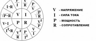
Let's make the pipe wider, leaving the number of stones the same - the water will feel better and the flow will increase.
Now let's replace the rough stones that we collected at the construction site with smooth stones from the sea. It is also easier to pass through them, which means the resistance decreases.
Electric current reacts to these parameters in a similar way: as the conductor lengthens, the resistance increases, as the cross-section (width) of the conductor increases, the resistance decreases, and if the material is changed, it will change depending on the material.
This pattern can be described by the following formula:
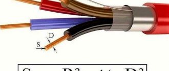
| Resistance R = ρl/S R - resistance [Ohm] l - conductor length [m] S - cross-sectional area [mm^2] ρ - resistivity [Ohm*mm^2/m] |
The unit of resistance is Ohm. Named after the physicist Georg Ohm.
Be careful!
The cross-sectional area of the conductor and the resistivity contain mm^2 in their units. In the table, resistivity is always given in this dimension, and it is easier to measure a thin conductor in mm^2. When multiplied, mm^2 is reduced and we get the value in SI.
But this does not negate the fact that each problem must be checked to ensure that it contains mm^2 in both quantities! If this is not the case, then you need to reduce the inappropriate value to mm^2.
Know! SI is the international system of units. “Convert to SI” means converting all quantities into meters, kilograms, seconds and other units of measurement without prefixes. The exception is the kilogram with the prefix “kilo”.
- The resistivity of a conductor is a physical quantity that shows the ability of a material to pass electric current. This is a tabular value, it depends only on the material.
Basic concept
Ever since the days of secondary school, namely such a subject as physics, information about the resistivity of the conductor has been present in our memory. Some people will no longer remember the exact definition, but they will remember for the rest of their lives what this term represents. Let us consider in more detail what the definition of this term sounds like - this is a physical component that characterizes the properties of a conductive component that interferes with the passage of electricity. This value is equal to the voltage present at the ends of the wire and the current that flows through this element. In this particular case, we looked at what determines the resistance of the conductor used. In addition, special formulas were provided in physics lessons that made it possible to calculate the necessary values of a given quantity, knowing only individual variables. While most people may not need this in everyday life, in a number of exceptional cases, when carrying out repair work on their own, the previously provided information may be required. Those who deal with electricity on an ongoing basis need to know all the information about this value.
Important. Previously, we looked at what resistance is, however, in order to more accurately understand this term, we should also consider additional information, as well as the calculation procedure and the materials used.
Ohmicity is one of the inductive properties of electrical circuits.
When AC voltage is applied to an electrical circuit, if the current passing through the circuit is in phase with the applied voltage, it means that the circuit is behaving ohmically.
Ohmic circuits contain resistance elements. However, even if an electrical circuit contains resistors, capacitors, and coil elements, the circuit can behave as an ohmic circuit. In this case, this means that capacitive and inductive effects cancel each other out.
In other words, this means that inductive and capacitive reactance cancel each other out.
2021 Reference books – Mobile version – Electrical engineering
• Electrical fuses.
• Modern magnets (determination of polarity, measurement of induction). • Uninterruptible Power Supply (UPS) • Solar batteries and thermogenerators (autonomous power supply). • Table of electrical resistivities (for metals, graphite, water and earth). • “Ground electric battery” – free energy (FE). • Batteries of various sizes - how to choose and test. Reminder on electrical engineering
Ohm's law establishes the relationship between the current strength in a conductor and the potential difference (voltage) at its ends. The formulation for a section of an electrical circuit (conductor) that does not contain sources of electromotive force (EMF): the current strength is directly proportional to the voltage and inversely proportional to the resistance of the conductor. Ohm's laws for a closed unbranched circuit: the current strength is directly proportional to the electromotive force and inversely proportional to the total resistance of the circuit. Ohm's law is valid for direct and quasi-stationary currents. It was discovered by the German physicist Georg Ohm in 1826. * Modern Encyclopedia
In the case of alternating current, the quantities included in the calculation formulas become complex.
Ohm's law in differential form describes exclusively the electrically conductive properties of a material, regardless of geometric dimensions.
The electrical resistivity of a substance is the electrical resistance of a cube made from it with sides equal to one (1 meter), when the current flows perpendicular to its two opposite faces, each with an area of 1 square meter.
Specific resistance depends on the concentration of free electrons in the conductor and on the distance between the ions of the crystal lattice, in other words, on the material of the conductor.
Dimension of electrical resistivity in system. SI (International System of Units) – Ohm m [Ohm*m^2/m]
(SI – Ω·m, Russian – Ohm-meter, English – ohm-meter).
To measure conductor materials, it is allowed to use a non-system unit - Ohm mm2/m
(for a millimeter cross-section of a conductor, 1 m long, that is, a millionth of an Ohm meter).
The physical meaning of resistivity: a material (homogeneous and isotropic*) has a specific electrical resistivity of one Ohm m, if a cube with a side of 1 meter made from this material has a resistance of 1 Ohm when measured on opposite faces of the cube. * Isotropy – identical physical properties in all directions.
Specific resistance characterizes the ability of a substance to conduct electric current and does not depend on the shape and size of the substance, but changes when its temperature differs from 20 °C (that is, from room temperature, at which the tabular values for reference books were determined).
In practice, in technology a unit is more often used that is a million times smaller (millimeter current-carrying cross-section) than Ohm m:
1 µOhm m (SI – µΩ m, Russian – microohm-meter, English – microhm-meter) = 1*10^-6 Ohm*m 1 µOhm m = 1 Ohm mm2/m
At the same time, the resistivity of a homogeneous piece of conductor 1 meter long and a current-carrying cross-sectional area of 1 square millimeter is equal to 1 Ohm mm2/m, if its resistance is 1 Ohm. For example, the resistivity value of electrical copper is approximately 1.72 * 10^-8 Ohm m = 0.0172 μOhm m (determined at a temperature of 20 degrees Celsius).
Depending on the resistivity, all substances are divided into conductors, dielectrics and semiconductors. Dielectrics (insulators, for example, porcelain) have very high electrical resistivity values, exceeding 10^12 Ohm m, and conductors (for example, silver, copper) - less than 10^-2 Ohm m (
Ratios:
1 Ohm mm2/m = 1 μOhm m ( 1 * 10^-6 Ohm * m ) 1 Ohm cm = 0.01 Ohm m 1 Ohm m = 100 Ohm cm (Ohm-centimeter) )
Electrical conductivity is the reciprocal of electrical resistance. The SI unit of electrical conductivity is Siemens (denoted by Sm). For example, copper has an electrical conductivity of approximately 58,100,000 S/m (1 / 58100000 ~ 0.0172 x 10⁻⁶ ohm.m), measured at 20 °C
Formula for calculating electrical resistance at constant current
R = (p * L) / S
where: R – electrical resistance of the wire; p – resistivity: p [Ohm mm2/m] = (R * S) / L [ Om * mm^2 / m ] L – length, m; S – cross section: square meter or millimeter (m2 or mm2). S = 3.14 * (radius)^2
If the electrical resistivity is in Ohm mm2/m, then S (section) should be in mm2, L (length) should be in meters. If in Ohm cm (Ohm-centimeter, abbreviated from Ohm*cm^2 / cm), then S is in cm2, L is in centimeters. If the specific resistance is in Om·m (Ohm-meter, from Ohm*m^2 / m), then S is in m2, L is in meters.
1 Ohm mm2/m = 1 μOhm m (derived submultiple unit of electrical resistivity in the SI system, used in practice in technical calculations – millionth part Ohm•m)
For an electrician and an experienced radio amateur, the ability to estimate by eye the cross-section of an electrical wire, taking into account the insulation layer, is like the absolute pitch of a musician who immediately determines the pitch of the sounds heard and writes them down in the form of musical notes and register keys.
Example, as a sample for the ratio of quantities. Electrical resistivity of pure electrical copper (after treatment by recrystallization annealing), measured at a temperature of 20 °C:
0.0172 µOhm (micro-ohm meter, 10^-6 Ohm•m)
1.72*10^-2 Ohm*mm^2/m (actual electrical resistance of a copper conductor, 1 meter long and 1 mm2 cross-section)
1.72*10^-6 Ohm•cm (wire dimensions - in centimeters)
1.72*10^-8 Ohm•m (abbreviated from Ohm*m^2/m – meter cube, current-carrying cross-sectional area – 1m2, i.e. between opposite faces)
17.2 nOhm•m (nanohm-meter, 10^-9 Ohm•m)
Highly conductive metals (no more than 0.1 μOhm.m) are used for the manufacture of wires, conductive cores of cables, windings of electrical machines and transformers, etc. Metals and alloys of high resistance (at least 0.3 microohm-meter) are used for the production of standard resistors, rheostats, electrical measuring instruments, electric heating devices, incandescent lamp filaments, etc. Heating alloys must withstand prolonged operation in the open air without destruction at temperatures of at least 1000 °C.
Table of electrical resistivity values, µOhm m (microohm meter) = Ohm mm2/m (equal numerical values) at an ambient temperature of 20 degrees Celsius Silver – 0.015-0.016 Copper – 0.0172-0.0180 Gold – 0.024 Aluminum – 0.026-0.030 Tungsten – 0.053-0.055 Zinc 0.053-0.062 Nickel – 0.068-0.073 Brass (copper-zinc alloy) – 0.043-0.108 Iron – 0.098 Steel – 0.10-0.14 Tin – 0.12 Tin-pig tsovy solder – 0.14-0.16 Bronze alloys – 0.02-0.2 Lead – 0.217-0.227 Nickel – 0.4 Manganin – 0.42-0.48 Constantan – 0.48-0.52 Nichrome – 1 .05-1.40 Fechral – 1.15-1.35 Carbon-graphite brushes for electrical machines – 20-50 Carbon welding electrode – 50-90 µOhm m
Mineral water (with water mineralization – 2-7 grams per liter) – 1-4 *10^6 μOhm m = 1-4 Ohm•m Ground water – 10-50 *10^6 Wet / damp garden soil (top layer of soil , soil – after watering) – 20-60 *10^6
Why are high voltages used in electrical networks?
In a power transmission line, with constant transmitted power, its losses increase in direct proportion to the length of the power line and inversely proportional to the square of the emf. Thus, it is considered desirable to increase the voltage to values of tens (intra-city overhead and cable power transmission networks at 380 volts, 6, 10, 20, 35, 110, 220 and 330 kV) and hundreds of kilovolts (main ultra-high power transmission lines - power lines 500-750 kV and ultra-high voltage, 1150 kV and above) on alternating and direct current lines (150, 400, 800 kV). But, with such operating parameters, constantly growing consumption of electrical energy and frequent peak overloads, wear and tear of equipment, lack of reserve capacity, weather anomalies, local non-compliance with safety requirements, unprofessionalism and basic sloppiness can cause emergency situations and system accidents (now called English manner - blackout). For this reason, municipal authorities of any village and city have a constant headache in providing backup power sources (batteries and diesel generators) for uninterrupted power supply to social facilities under a backup scheme.
Special alloys based on copper, in electrical engineering
For high currents, up to 10 A, a high-power wire resistor called a rheostat is used. As a winding, a wire made of a thermostable (with a minimum temperature coefficient) alloy with high resistivity, for example, constantan (40% Ni, 1.2% Mn, 58.8% Cu), is used. If the voltage between adjacent turns does not exceed 1 volt, such a wire can be wound tightly, turn to turn, without special insulation between turns, due to the presence of a natural oxide film formed on the surface of a given metal, with rapid (no more than three seconds) heating to a sufficiently high temperature (about 900 °C).
In high-precision devices, manganin (3%Ni, 12%Mn, 85%Cu) is used, which is less heat-resistant, but, unlike constantan wire, has a very low thermoEMF (contact electrical potential difference) when paired with copper.
Designations of recommended multiples and sub-multiple values from SI units
10^9 Ohm – gigaohm GOhm GΩ 10^6 Ohm – megaohm MOhm MΩ 10^3 Ohm = 1000 Ohm – kiloohm kOhm kΩ. 10^-2 Ohm – centiohm cOhm cΩ 10^-3 Ohm – milliohm mOhm mΩ. 10^-6 Ohm – microohm µOhm µΩ 10^-9 Ohm – nanoohm nOhm nΩ
Dependence of resistance on temperature
When heated, the electrical resistance of metal conductors increases, and when cooled, it decreases. To calculate, according to the formula, electrical resistance at a certain temperature, the so-called “temperature coefficient of resistance” (TCR) is used. Calculations are carried out from a certain initial temperature level. For a temperature range within normal weather conditions (in winter and summer) of the environment, the dependence for the conductor is described by the mathematical formula:
R2 = R1 * (1 + α * (t2 – t1)),
where R1 (initial, known value, at zero or 20 degrees Celsius, measured or calculated) and R2 (desired) are the resistor resistances, respectively, at temperatures t1 (0 ° C or 20 ° C) and t2; α – temperature coefficient of resistance (from the reference table), equal to the relative change in electrical power. resistance (specific or absolute) when the temperature changes by 1 °C. Since TCR values are very small, in reference books they are indicated in units of thousandths or millionths (ppm/°C - Parts Per Million) of a relative change in resistance per degree.
Usually, the initial, tabulated values of various physical constants are given either to normal room temperature +20 ° C or to zero (in reference tables of conductor and rheostatic materials used in electrical devices).
In metal thermometers made from copper or platinum wire, the electrical resistance increases almost linearly with increasing temperature (without extremely high values for these materials). But, when, for example, a thin copper wire is heated excessively to a red-hot temperature, its active electrical resistance to direct current increases many times over.
Calculation example for a hundred-meter aluminum busbar, with a radius of 40 mm, heated to 95°C: R = (R1 * (1 + α * (t2–t1))) * L / S = = 2.62*10-8 Ohm•m * (1 + 0.0042*95) * 100 / (3.14 * 402 * 10-6) = 7.3 * 10-4 Ohm where: S – cross-sectional area in m2 (minus the thickness of the insulation layers), L – length of the conductor in meters.
Temperature coefficient of resistance x10-3, 1/degree: Aluminum – 4.2 Hard-drawn tin bronze – 0.6-0.7 Tungsten – 4.2 Graphite – -1.3 Dural – 2.2 Constantan – 0.003-0.005 Brass – 1.5 Manganin – 0.03-0.06 (at temperatures up to 250-300°C) Copper – 4.3 Nichrome – 0.14 Silver – 4.0 Steel – 9.0 Zinc – 4.2
Fixed resistors and their markings
In the alphanumeric (code) marking of resistors - the numerical value of the electrical resistance and the letters are applied to their body, the first of which indicates the multiplier (R or E - Ohm, K - kiloohm, M - megohm) and, at the same time, determines the position of the decimal point sign. The second letter means the accuracy class, that is, the permissible deviation from the specified value. Ratings for small parts are applied in the form of markings with colored rings, stripes or dots (depending on the standard used). Each color corresponds to a specific number indicating the number of ohms, multiplier/power or percentage of accuracy. To quickly determine the resistor value by color coding, special computer programs are used. Read more…
An example of a calculation based on a school physics problem from the 9th grade curriculum.
Task: determine (find in the table), based on the known resistivity p = 0.017 Ohm mm2/m - what material is this? Calculate the wire diameter. Calculate the electrical resistance of a wire with a length L = 80 cm, cross section S = 0.2 mm2 Solution to the problem: From the table we determine that copper can have a resistivity equal to 0.017 Ohm mm2/m.
From the formula S = 3.1416 * (radius)^2 = 3.142 * ((diameter)^2)/4 using your calculator, find the diameter (in millimeters) = square root of (4 * S / 3.14)
Wire length, in SI units (converted to meters): 80 cm = 0.8 m
We find the electric resistance according to the formula: R = (p * L) / S = (0.017 * 0.8) / 0.2 = 0.068 Ohm
Answer: accurate to the second decimal place, R = 0.07 Ohm
[ to Home Page ]
Place an ad
The latest financial news from the site Finversiya.ru Electrical work - electrical installation, connection and maintenance of electrical wiring. | Mini-handbook on electrical parameters: ratios of Ohm x mm2/m and µOhm x m (micro-ohm), in technical calculations for metals, alloys and powder mixtures.
Copyright © 2007-2021, KAKRAS.RU
What does it depend on
The electrical resistance of the conductors used is not a constant value, it depends on a number of individual points. Let us consider in more detail the dependence of this value:
- A material that is used as a conductive element for electric current.
- The length, and in addition, the cross-sectional area of the wiring used, which are present in the circuit.
- The order of connecting resistors and wiring (parallel or series combination).
- In addition, the dependence of the conductor on the temperature that is present inside the conductive element is highlighted.
- A load that is applied from a power source to the ends of a conductive element where the size is calculated.
- The amount of electrical current that is present within a single closed circuit used to calculate values.
- The existing atmosphere (for example, in sub-zero weather and on a hot day, the resistance of some materials is different).
- The age of the source of energy passage used (as is known, any material deteriorates over time, which is why its resistance decreases).
Important. In practice, metals are almost always used as conductive materials, since these elements have the smallest size, which allows electricity to move freely through them.
Use of substances for the manufacture of conductors and isolates
Which substances have the highest resistivity values? Of course, with dielectrics. For example, ebonite and porcelain practically do not conduct electricity. That's why they are used as insulators .
Pure metals have the lowest resistivity. Silver and copper are the best conductors of electricity.
What substances are conductors used in practice made from? Most often, copper, aluminum and iron wires are used for wiring electrical circuits.
In Table 1, you may also have noticed the resistivity values for alloys of several substances. They have quite large values. For what? They are usually used for the manufacture of devices that need to have a high resistance for normal functioning, but still pass current.
Ohm's law.
And here the fundamental law of all electronics – Ohm’s law – comes to our aid:
The current in a circuit is directly proportional to the voltage and inversely proportional to the resistance of the section of the circuit in question.
Let's consider the simplest electrical circuit: As follows from Ohm's law, the voltage and current in the circuit are related as follows:
I = frac{U}{R}
Let the voltage be 10 V and the circuit resistance be 200 ohms. Then the current in the circuit is calculated as follows:
I = frac{10}{200} = 0.05 = 50medspacemA
Formula for calculation
Any calculation starts with a formula. The basic formula for calculating conductor resistance is:
R=(ρ*l)/S
Where R is the resistance in Ohms, ρ is the resistivity, l is the length in m, S is the cross-sectional area of the wire in mm2.
This formula is suitable for calculating the resistance of a wire by cross-section and length. It follows from it that the resistance changes depending on the length; the longer, the greater. And on the contrary, depending on the cross-sectional area, the thicker the wire (large cross-section), the lower the resistance. However, the quantity designated by the letter ρ (Po) remains unclear.
Experimental results
What conclusions can we draw after all the calculations?
- Of two nickel wires of the same thickness, longer wire has greater resistance.
- The nickel wire with a smaller cross-section a greater resistance . In this case, the length of the wires was the same
- Nickelin and nichrome wires have different resistances with the same dimensions
Calculating resistance
All data can be obtained from the tables.
So, we remember - the wire is thicker, the resistance is less. The following will provide instructions on how to calculate everything accurately.
- To do this, we need to find out the resistivity of the conductor material. In ordinary networks you are unlikely to find silver wires, so we take standard copper as a basis. It is 0.017.
- The wire resistance itself is calculated using the following formula: ; where R is the resistance, p is the resistivity of the conductor, l is the length of the wire and s is its cross-sectional area.
- Let's assume that your stoves together can load a network of 16 Amps, this means that we can take a wire with an area of 0.75 mm2. We remember that you require a minimum of 20 meters. So, we consider: 0.017*20/0.75 = 0.45 Ohm
- You can use the table, but the result will not be as accurate. We see that 100 meters of copper wire of the cross-section we need has a resistance of 2.38 Ohms. We divide this value by five (up to 20 meters) and get 0.476 Ohms - the difference is at the level of error, but still.
- Due to the fact that electricity flows through two wires, we multiply the resulting value by 2 and get 0.9 Ohm.
- Now you can calculate the voltage loss using the formula: dU = R*I = 0.9*16 = 14.4 Volts.
- We convert the resulting voltage into a percentage: 14.4V/220V*100 = 6.54%
According to existing standards, 5% voltage loss is allowed. As you can see, in our case the value turned out to be larger, which means that the conductor resistance is too high, so we increase the cross-section of the wire and repeat the calculations.
So, we have found the resistance of the wire, and as you can see, doing this with your own hands and head is not so difficult. The attached video will help you understand the material further. Approach the matter wisely, because the price is the safety of you and your home.
Coil
An inductor is a metal or ferrite core around which several turns of copper wire are wound. The element has the following properties:
- Due to inductance, the rate of change of currents is limited.
- As the frequency of the current increases, the coil is able to increase its resistance (skin effect).
- Creates a magnetic field.
- Increases and accumulates tension.
- Creates a phase shift in alternating current.
- Proportional to the speed of current movement, it creates a self-inductive emf.
All these properties are used in the development of radio receivers, frequency generators, testers, magnetometers and other types of complex equipment.
How to find ohmic resistance in a circuit?
It can be learned from Ohm's law, which relates current, voltage and resistance. In this case, it is calculated using the formula
resistance formula through Ohm's law
Where
R - resistance, Ohm
U - voltage at the ends of the conductor, Volts
I - current flowing through the conductor, Amperes
That is, we just need to measure the voltage at the ends of a conductor and measure the current passing through it. Then apply the formula and calculate the conductor resistance. Let's solve a simple problem to consolidate.
Task
Calculate the resistance of the conductor if it is known that a voltage of 5 Volts is applied to it and the current passing through it is 0.1 Ampere.
Solution
We use the formula
In electronics and electrical engineering, special radioelements are used that resist electric current - resistors. You can read more about them in this article. fixed resistors
Also here is a video where a very smart teacher explains what resistance is
Ohm's law for a circuit section
With pebbles in a pipe, everything is clear, but not only does the force with which the flow of water flows through the pipe depend on them, it also depends on the pump with which we pump this water. The harder we pump, the stronger the current. In an electrical circuit, the pump function is performed by a current source.
For example, the source may be a galvanic cell (a conventional battery). A battery works based on chemical reactions inside it. These reactions release energy, which is then transferred to the electrical circuit.
Any source necessarily has poles - “plus” and “minus”. The poles are its extreme positions, essentially the terminals to which the electrical circuit is connected. Actually, the current flows from “+” to “-”.
We already have two quantities on which the electric current in the circuit depends - voltage and resistance. It seems it is time to combine them into law.
The current strength in a section of a circuit is directly proportional to the voltage at its ends and inversely proportional to its resistance.
Mathematically it can be described like this:
| Ohm's law for a circuit section I = U/R I - current strength [A] U - voltage [V] R - resistance [Ohm] |
Voltage is measured in Volts and shows the difference between two points in the circuit: this difference determines how much current will flow - the greater the difference, the higher the voltage and the stronger the current will flow.
Current strength is measured in Amperes, and you can read more about it in our article
Let's solve several problems using Ohm's Law for a section of a circuit.
Task times
Find the current strength in an incandescent light bulb if the floor lamp is connected to a 220 V network and the resistance of the filament is 880 Ohms.
Solution:
Let's take Ohm's law for a section of the circuit:
I = U/R
Let's substitute the values:
I = 220/880 = 0.25 A
Answer: The current passing through the light bulb is 0.25 A
Let's make it more difficult. And we will find the current strength, I know all the parameters for calculating the resistance and voltage.
Problem two
Find the current strength in an incandescent light bulb if the floor lamp is connected to a 220 V network, and the length of the filament is 0.5 m, the cross-sectional area is 0.01 mm^2, and the resistivity of the filament is 1.05 Ohm*mm^2/ m.
Solution:
First, let's find the resistance of the conductor.
R = ρl/S
The area is given in mm^2, and the resistivity also contains mm^2 in dimension.
This means that you can substitute values without converting to SI:
R = 1.05*0.5/0.01 = 52.5 Ohm
Now let's take Ohm's law for a section of the circuit:
I = U/R
Let's substitute the values:
I = 220/52.5 ≃ 4.2 A
Answer: The current passing through the light bulb is approximately 4.2 A
Now let's make it even more complicated! Let's determine the material from which the filament is made.
Problem three
What material is the filament of the light bulb made of, if the table lamp is connected to a 220 V network, the length of the filament is 0.5 m, its cross-sectional area is 0.01 mm^2, and the current in the circuit is 8.8 A
Solution:
Let's take Ohm's law for a section of the circuit and express the resistance from it:
I = U/R
R = U/I
Let's substitute the values and find the resistance of the thread:
R = 220/8.8 = 25 Ohm
Now let’s take the resistance formula and express the resistivity of the material from it:
R = ρl/S
ρ = RS/l
Let's substitute the values and get:
ρ = 25*0.01/0.5 = 0.5 Ohm*mm^2/m
Let's refer to the material resistivity table to find out what material this filament is made of.
Design and varieties
All types of inductors have the same design, regardless of their application. The features introduced to obtain individual parameters affect the type of part.
- Solenoid. Component with increased overall length of winding wire. The winding is larger than the diameter of the part.
- Toroidal. In such a coil, the solenoid is made in the shape of a “torus”.
- Multilayer type, has several rows of winding.
- Sectioned. The winding has several divided sections, sometimes made of wire of different sections. The best known coil of this type is the transformer or choke.
- Universal, can combine several winding options at once.
Regardless of design, all coils operate on the same principle.
Ohm's law for a complete circuit
We have dealt with Ohm's law for a section of a circuit. Now let's find out what happens if the circuit is complete: it has a source, conductors, resistors and other elements.
In this case, Ohm's Law is introduced for a complete circuit: the current strength in a complete circuit is equal to the ratio of the EMF of the circuit to its total resistance.
EMF stands for electromotive force. It is denoted by the Greek letter ε and is measured, like voltage, in Volts.
- EMF is the force that moves charged particles in a circuit. It is taken from the current source. For example, from a battery.
A chemical reaction inside a galvanic cell (this is synonymous with a battery) occurs with the release of energy into an electrical circuit. It is this energy that causes particles to move along the conductor.
Voltage and EMF are often equated and said to be the same thing. Formally, this is not so, but when solving problems, most often there really is no difference, since these quantities are both measured in Volts and define processes that are very similar in essence.
In the form of a formula, Ohm's Law for a complete circuit will look like this:
| Ohm's law for a complete circuit I = ε/(R + r) I - current strength [A] ε - EMF [V] R - resistance [Ohm] r - internal source resistance [Ohm] |
No source is perfect. In problems this is possible (“consider the source ideal,” these are the phrases), but in real life it’s definitely not. In this regard, the source has internal resistance, which prevents the flow of current.
Let's solve the problem for a complete circuit.
Problem
Find the current in a complete circuit consisting of one resistor with a resistance of 3 Ohms and a source with an emf equal to 4 V and an internal resistance of 1 Ohm
Solution:
Let's take Ohm's law for a complete circuit:
I = ε/(R + r)
Let's substitute the values:
I = 4/(3+1) = 1 A
Answer: The current in the circuit is 1 A.
Addiction
The amount of active resistance largely depends on the diameter of the conductors. When high-frequency currents are applied, the resistance of the conductor can be reduced only if its surface layer is much thinner than the main one. In order to achieve an ideal cross-section, this layer must consist of a material with very high conductivity, such as gold or silver. This effect occurs due to the interaction of voltage and the magnetic field formed by it. The field strongly influences the current flowing through the conductor and pushes it to the surface layer. Thus, closer to the surface of the conductor, the conductivity decreases and becomes critically small in its upper layer.
The following effects are also present: leakage losses and dielectric losses. Both effects are associated with the presence of a capacitor in the circuit. Dielectric losses occur due to an increase in the temperature of the dielectric inside the capacitor. Leakage loss occurs due to the breakdown fraction of the capacitor insulator.
Hysteresis. This is also a type of AC energy loss. This loss occurs when a magnetic field forms around metal objects. Electromagnetic influence leads to heating of the metal, which means energy conversion.
The last leakage factor is radio emission. Radio waves appear due to a strong magnetic field and its interaction with the metals of the circuit. For suppression, especially in radio equipment, screens are used that absorb part of the field and repel the rest.
Table of resistivities of various materials
| Specific resistance ρ, Ohm*mm2/m | Specific resistance ρ, Ohm*mm2/m |
| Aluminum | 0,028 |
| Bronze | 0,095 – 0,1 |
| Bismuth | 1,2 |
| Tungsten | 0,05 |
| Iron | 0,1 |
| Gold | 0,023 |
| Iridium | 0,0474 |
| Constantan (Ni-Cu + Mn alloy) | 0,5 |
| Brass | 0,025 – 0,108 |
| Magnesium | 0,045 |
| Manganin (alloy of copper, manganese and nickel – instrument) | 0,43 – 0,51 |
| Copper | 0,0175 |
| Molybdenum | 0,059 |
| Nickel silver (an alloy of copper, zinc and nickel) | 0,2 |
| Sodium | 0,047 |
| Nickelin (an alloy of copper and nickel) | 0,42 |
| Nickel | 0,087 |
| Nichrome (an alloy of nickel, iron chromium and manganese) | 1,05 – 1,4 |
| Tin | 0,12 |
| Platinum | 0.107 |
| Mercury | 0,94 |
| Lead | 0,22 |
| Silver | 0,015 |
| Steel | 0,103 – 0,137 |
| Titanium | 0,6 |
| Hromal | 1,3 – 1,5 |
| Zinc | 0,054 |
| Cast iron | 0,5-1,0 |
How to measure the ohmic resistance of cable insulation
Before testing, remove residual charge from disconnected live parts. This is done by connecting them to the ground bus. The contact jumper is removed only after connecting the measuring device. At the end of the test, the residual charge is removed again by briefly shorting it to ground. You can find the resistance value in two ways: either using a calculation or a table, or directly using instruments.
According to the PUE table
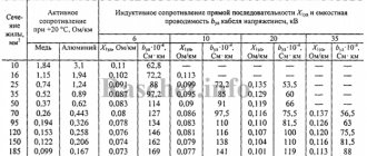
Resistance values depend on the cross-section of the element conducting the electric current and the material from which it is made.
Aluminum wire table
This is usually copper or aluminum. The main values are shown in the table:
Table for copper wire
Using instruments
Typically, the equipment used to make measurements is divided into two groups: panel meters and meggers. The first is used for mobile or stationary electrical installations with an independent neutral. Indicators and relay components are included in a typical insulation monitoring equipment design. These meters can operate in continuous mode and can be used in 220 V or 380 V AC networks with different frequencies.
In most cases, the measurement is made using a megger. It differs from conventional ohmmeters in that it can operate at fairly high voltage values generated by the device itself. There are two types of megohmmeters:
- Analog.
Analog device
- Digital.
Digital sensor A standard megger contains three sensors. The following are connected to them: protective grounding, test leads, shielding. The latter is used to eliminate leakage current.
The measurement method can be expressed as follows:
- The test voltage is selected according to the requirements of the production line. For example, for home wiring, the value is set in the range from 100 to 500 V.
- When using a digital device, you must press the “Test” button, and on an analog device, turn the knob until the indicator shows the required voltage value.
- Connect the linear output of the tester to the test core of the cable, and the grounding output to the harness of the remaining wires. That is, each core is checked in relation to the remaining electrical wires electrically connected to each other.
Important! If the received data is unsatisfactory, each core in the cable is checked separately.
- Record all obtained values and compare them with specifications.
Connecting the sensor to cables
Physical meaning of active resistance (Z)
The concept of a Z circuit is slightly different from the concept of an Ohmic R. In a current circuit, the conversion of electrical energy into mechanical energy can occur. For example, when operating an electric motor or chemical, when charging a battery.
In an AC circuit, electromagnetic energy can be absorbed into the coil core. Energy can be transferred from one circuit to another.
In the case of alternating current, its density in the wires decreases, so the working cross-section of the wire turns out to be less than the geometric size. The actual active R increases compared to the resistance value determined by the specific type. As a result, when using alternating current, the conductor heats up more than when using direct current.
Therefore, in high-frequency radio engineering, conductors are ribbed and the surface is coated with silver or gold, which prevents oxidation.
Active R formula: Z=U*I.