Transformer design
If you look at the transformer from the outside, it is an W-shaped device consisting of a metal core, a cardboard or plastic frame and a copper wire winding.
There are two windings. The core is several steel plates that are treated with a special varnish and connected to each other. The varnish is applied specifically to prevent tension from passing between the plates. In this way they fight the so-called eddy currents (Foucault currents). The thing is that Foucault currents will simply heat the core itself. And these are losses.
The composition of the core plates is also associated with losses. Transformer iron (as core steel is most often called by experts), if you look at it in cross-section, consists of large crystals, which, in turn, are isolated from each other by an oxide film.
What is the efficiency of a transformer and what does it depend on?
Efficiency (the full interpretation of this abbreviation) is the ratio of useful electricity to that supplied to the device.
In addition to energy, the efficiency indicator can be determined by calculation based on power indicators based on the ratio of the useful value to the total value. This characteristic is very important when choosing a device and determines the effectiveness of its use.
The magnitude of the efficiency depends on the energy losses that are allowed during the operation of the device. These losses are of the following types:
- electrical - in the conductors of the coils;
- magnetic - in the core material.
The magnitude of these losses when designing a device depends on the following factors:
- overall dimensions of the device and shape of the magnetic system;
- compactness of the coils;
- density of assembled sets of plates in the core;
- diameter of wire in coils.
Reducing losses in the unit is achieved during the design process of the device, using soft magnetic ferromagnetic materials for the manufacture of the core. Electrical steel is assembled into thin plates, insulated relative to each other by a special layer of applied varnish.
During operation, the efficiency of the device is determined by:
- applied load;
- dielectric medium - a substance used as a dielectric;
- uniformity of load supply;
- oil temperature in the unit;
- degree of heating of the coils and core.
If during operation the unit is constantly underloaded or the specified operating conditions are violated, in addition to the risk of failure, this leads to a decrease in the efficiency of the device.
Transformer windings
These same coils of wire in a transformer are called windings. The windings mainly consist of varnished copper wire. Such a wire is in varnish insulation, therefore, the wire in the winding does not short-circuit with each other. A winding transformer wire looks something like this.
It can be of different diameters. It all depends on what load this or that transformer is designed for.
The simplest single-phase transformer can have two such windings.
The winding to which voltage is applied is called the primary winding. People also call it “primary”. The winding from which the voltage has already been removed is called secondary or “secondary”.
In order to find out where the primary winding is and where the secondary is, just look at the transformer nameplate.
I/P: 220M50Hz (RED-RED) - this tells us that the two red wires are the primary winding of the transformer, to which we supply a mains voltage of 220 Volts. Why do I think this is primary? I/P means InPut, which is translated as “input”.
O/P: 12V 0.4A (BLACK, BLACK) – secondary winding of the transformer with an output voltage of 12 Volts (OutPut). The maximum current that this transformer can supply to the load is 0.4 Ampere or 400 mA.
Can I use a planar transformer?
Of course you can. But the question is whether it is necessary. A planar transformer is a device based on a printed circuit board. The use of such models is indispensable for compact equipment such as phones, computers and others.
However, if we are talking about replacing or independently designing a device, then such an innovative technology is not needed due to the high cost and complexity of installation.
There is no need to reinvent the wheel: there are a number of methods for calculating, creating and installing traditional transformers that are ready to perform almost any task for the user. The use of a planar transformer is justified only if the device requires special compactness and mobility.
How the device works
A transformer is an electrical device designed to transmit energy without changing its shape and frequency. Using the phenomenon of electromagnetic induction in its work, the device is used to convert an alternating signal or create galvanic isolation. Each transformer is assembled from the following structural elements:
- core;
- windings;
- frame for winding arrangement;
- insulator;
- additional elements ensuring the rigidity of the device.
The principle of operation of any transformer device is based on the effect of the appearance of a magnetic field around a conductor with an electric current flowing through it. This field also occurs around magnets. Current is the directional flow of electrons or ions (charges). By taking a wire conductor and winding it around a coil and connecting a potential measuring device to its ends, you can observe a surge in the voltage amplitude when the coil is placed in a magnetic field. This suggests that when a magnetic field is applied to a coil with a wound conductor, an energy source or energy converter is obtained.
In a transformer design, such a coil is called primary or mains. It is designed to create a magnetic field. It is worth noting that such a field must necessarily change in direction and magnitude all the time, that is, be variable.
A classic transformer consists of two coils and a magnetic circuit connecting them. When an alternating signal is applied to the contacts of the primary coil, the resulting magnetic flux is transmitted through the magnetic circuit (core) to the second coil. Thus, the coils are connected by magnetic power lines. According to the rule of electromagnetic induction, when the magnetic field changes, an alternating electromotive force (EMF) is induced in the coil. Therefore, a self-induction emf occurs in the primary coil, and a mutual induction emf occurs in the secondary coil.
The number of turns on the windings determines the amplitude of the signal, and the diameter of the wire determines the greatest current strength. If the turns on the coils are equal, the input signal level will be equal to the output. In the case where the secondary coil has three times as many turns, the amplitude of the output signal will be three times greater than the input - and vice versa.
The heating of the entire device depends on the cross-section of the wire used in the transformer. It is possible to select the correct cross-section using special tables from reference books, but it is easier to use an online transformer calculator.
The ratio of the total magnetic flux to the flux of a single coil sets the strength of the magnetic coupling. To increase it, the windings of the coils are placed on a closed magnetic circuit. It is made from materials with good electromagnetic conductivity, for example, ferrite, alsifer, carbonyl iron. Thus, three circuits arise in the transformer: an electrical circuit - formed by the flow of current in the primary coil, an electromagnetic circuit - forming a magnetic flux, and a second electrical circuit - associated with the appearance of current in the secondary coil when a load is connected to it.
The correct operation of the transformer also depends on the frequency of the signal. The larger it is, the less losses occur during energy transfer. This means that the dimensions of the magnetic circuit depend on its value: the higher the frequency, the smaller the dimensions of the device. Pulse converters are built on this principle, the manufacture of which is associated with development difficulties, so a calculator is often used to calculate a transformer according to the core cross-section, which helps to get rid of manual calculation errors.
Principle of operation
The main feature of pulse-type transformers (hereinafter referred to as IT) is that they are supplied with unipolar pulses with a constant current component, and therefore the magnetic circuit is in a state of constant magnetization. Below is a schematic diagram of connecting such a device.
Diagram: connecting a pulse transformer
As you can see, the connection diagram is almost identical to conventional transformers, which cannot be said about the timing diagram.
The primary winding receives pulse signals having a rectangular shape e (t), the time interval between which is quite short. This causes the inductance to increase during the interval tu, after which its decline is observed in the interval (T-tu).
Induction changes occur at a speed that can be expressed in terms of a time constant using the formula: τ p =L 0 /R n
The coefficient describing the difference in the inductive differential is determined as follows: ∆V=V max – V r
- В max – level of maximum induction value;
- In r – residual.
The difference in induction is shown more clearly in the figure, which shows the displacement of the operating point in the magnetic conductor circuit of the IT.
As can be seen in the timing diagram, the secondary coil has a voltage level U 2 in which reverse emissions are present. This is how the energy accumulated in the magnetic circuit manifests itself, which depends on magnetization (parameter iu).
The current pulses passing through the primary coil are trapezoidal in shape, since the load and linear currents (caused by the magnetization of the core) are combined.
The voltage level in the range from 0 to tu remains unchanged, its value e t =U m. As for the voltage on the secondary coil, it can be calculated using the formula:
wherein:
- Ψ – flux linkage parameter;
- S is a value that reflects the cross-section of the magnetic core.
Considering that the derivative, which characterizes changes in the current passing through the primary coil, is a constant value, the increase in the induction level in the magnetic circuit occurs linearly. Based on this, it is permissible, instead of the derivative, to enter the difference between the indicators taken over a certain time interval, which allows you to make changes to the formula:
in this case, ∆t will be identified with the parameter tu, which characterizes the duration with which the input voltage pulse occurs.
To calculate the area of the pulse with which the voltage is generated in the secondary winding of the IT, it is necessary to multiply both parts of the previous formula by tu. As a result, we arrive at an expression that allows us to obtain the main IT parameter:
U mxtu =S x W 1 x ∆V
Note that the magnitude of the pulse area directly depends on the parameter ∆B.
The second most important quantity characterizing the operation of IT is the induction drop; it is influenced by such parameters as the cross-section and magnetic permeability of the magnetic core, as well as the number of turns on the coil:
Here:
- L 0 – induction difference;
- µ a – magnetic permeability of the core;
- W 1 – number of turns of the primary winding;
- S – cross-sectional area of the core;
- l cр – length (perimeter) of the core (magnetic core)
- In r – the value of residual induction;
- In max – the level of the maximum induction value.
- H m – Magnetic field strength (maximum).
Considering that the inductance parameter of the IT completely depends on the magnetic permeability of the core, when calculating it is necessary to proceed from the maximum value of µ a, which is shown by the magnetization curve. Accordingly, for the material from which the core is made, the level of the parameter B r, which reflects the residual induction, should be minimal.
Video: detailed description of the operating principle of a pulse transformer
Based on this, a tape made of transformer steel is ideal as an IT core material. You can also use permalloy, which has a minimum squareness coefficient.
Cores made of ferrite alloys are ideal for high-frequency IT, since this material has low dynamic losses. But due to its low inductance, IT has to be made in large sizes.
Purpose and functionality
So, what functions does a transformer perform?
- This is a reduction in voltage to the required parameters.
- With its help, the galvanic isolation of the network is reduced.
As for the second function, it is necessary to give explanations. Both windings (primary and secondary) of the current transformer are not directly connected to each other. This means that the resistance of the device, in fact, should be infinite. True, this is an ideal option. The connection of the windings occurs through the magnetic field created by the primary winding. This is such a complex functionality.
Alternative method for dimensions
The approximate parameters of the transformer, based on the available core, can be determined in another way, and then conclusions can be drawn about the possibility of further use.
Knowing the cross-sectional area of the magnetic circuit in square centimeters, you can estimate the maximum power that this converter is capable of providing:
PG=S2
It should be borne in mind that this power is dimensional, and the real one will have a smaller value:
P=0.8 PG
Usually, provided that the calculated power matches the required one, the primary winding connected to the 220 V network can be left untouched, recalculating only the parameters at the outputs.
How to measure wire diameter
If you have a micrometer lying around at home, you can use it to measure the diameter of the wire.
It is better to first heat the wire in a match flame and only then remove the weakened insulation with a scalpel. If this is not done, then part of the copper can be removed along with the insulation, which will reduce the accuracy of the measurement, especially for a thin wire.
If you don’t have a micrometer, you can use an ordinary ruler. You need to wind 100 turns of wire around the tip of a screwdriver or another suitable axis, compress the turns with your fingernail and attach the resulting set to a ruler. Dividing the result by 100, we get the diameter of the wire with insulation. You can find out the diameter of the copper wire from the table below.
Example.
I wound 100 turns of wire and got a set length of -39 mm.
39 / 100 = 0.39 mm
Using the table, I determine the diameter of the copper wire - 0.35 mm.
Winding Wire Data Table
| Diameter without insulation, mm | Copper cross section, mm² | Resistance 1m at 20ºС, Ohm | Permissible load at current density 2A/mm² | Diameter with insulation, mm | Weight 100m with insulation, g |
| 0,03 | 0,0007 | 24,704 | 0,0014 | 0,045 | 0,8 |
| 0,04 | 0,0013 | 13,92 | 0,0026 | 0,055 | 1,3 |
| 0,05 | 0,002 | 9,29 | 0,004 | 0,065 | 1,9 |
| 0,06 | 0,0028 | 6,44 | 0,0057 | 0,075 | 2,7 |
| 0,07 | 0,0039 | 4,73 | 0,0077 | 0,085 | 3,6 |
| 0,08 | 0,005 | 3,63 | 0,0101 | 0,095 | 4,7 |
| 0,09 | 0,0064 | 2,86 | 0,0127 | 0,105 | 5,9 |
| 0,1 | 0,0079 | 2,23 | 0,0157 | 0,12 | 7,3 |
| 0,11 | 0,0095 | 1,85 | 0,019 | 0,13 | 8,8 |
| 0,12 | 0,0113 | 1,55 | 0,0226 | 0,14 | 10,4 |
| 0,13 | 0,0133 | 1,32 | 0,0266 | 0,15 | 12,2 |
| 0,14 | 0,0154 | 1,14 | 0,0308 | 0,16 | 14,1 |
| 0,15 | 0,0177 | 0,99 | 0,0354 | 0,17 | 16,2 |
| 0,16 | 0,0201 | 0,873 | 0,0402 | 0,18 | 18,4 |
| 0,17 | 0,0227 | 0,773 | 0,0454 | 0,19 | 20,8 |
| 0,18 | 0,0255 | 0,688 | 0,051 | 0,2 | 23,3 |
| 0,19 | 0,0284 | 0,618 | 0,0568 | 0,21 | 25,9 |
| 0,2 | 0,0314 | 0,558 | 0,0628 | 0,225 | 28,7 |
| 0,21 | 0,0346 | 0,507 | 0,0692 | 0,235 | 31,6 |
| 0,23 | 0,0416 | 0,423 | 0,0832 | 0,255 | 37,8 |
| 0,25 | 0,0491 | 0,357 | 0,0982 | 0,275 | 44,6 |
| 0,27 | 0,0573 | 0,306 | 0,115 | 0,31 | 52,2 |
| 0,29 | 0,0661 | 0.2bb | 0,132 | 0,33 | 60,1 |
| 0,31 | 0,0755 | 0,233 | 0,151 | 0,35 | 68,9 |
| 0,33 | 0,0855 | 0,205 | 0,171 | 0,37 | 78 |
| 0,35 | 0,0962 | 0,182 | 0,192 | 0,39 | 87,6 |
| 0,38 | 0,1134 | 0,155 | 0,226 | 0,42 | 103 |
| 0,41 | 0,132 | 0,133 | 0,264 | 0,45 | 120 |
| 0,44 | 0,1521 | 0,115 | 0,304 | 0,49 | 138 |
| 0,47 | 0,1735 | 0,101 | 0,346 | 0,52 | 157 |
| 0,49 | 0,1885 | 0,0931 | 0,378 | 0,54 | 171 |
| 0,51 | 0,2043 | 0,0859 | 0,408 | 0,56 | 185 |
| 0,53 | 0,2206 | 0,0795 | 0,441 | 0,58 | 200 |
| 0,55 | 0,2376 | 0,0737 | 0,476 | 0,6 | 216 |
| 0,57 | 0,2552 | 0,0687 | 0,51 | 0,62 | 230 |
| 0,59 | 0,2734 | 0,0641 | 0,547 | 0,64 | 248 |
| 0,62 | 0,3019 | 0,058 | 0,604 | 0,67 | 273 |
| 0,64 | 0,3217 | 0,0545 | 0,644 | 0,69 | 291 |
| 0,67 | 0,3526 | 0,0497 | 0,705 | 0,72 | 319 |
| 0,69 | 0,3739 | 0,0469 | 0,748 | 0,74 | 338 |
| 0,72 | 0,4072 | 0,043 | 0,814 | 0,78 | 367 |
| 0,74 | 0,4301 | 0,0407 | 0,86 | 0,8 | 390 |
| 0,77 | 0,4657 | 0,0376 | 0,93 | 0,83 | 421 |
| 0,8 | 0,5027 | 0,0348 | 1,005 | 0,86 | 455 |
| 0,83 | 0,5411 | 0,0324 | 1,082 | 0,89 | 489 |
| 0.86 | 0,5809 | 0,0301 | 1,16 | 0,92 | 525 |
| 0,9 | 0,6362 | 0,0275 | 1,27 | 0,96 | 574 |
| 0,93 | 0,6793 | 0,0258 | 1,36 | 0,99 | 613 |
| 0,96 | 0,7238 | 0,0242 | 1,45 | 1,02 | 653 |
| 1 | 0,7854 | 0,0224 | 1,57 | 1,07 | 710 |
| 1,04 | 0,8495 | 0,0206 | 1,7 | 1,12 | 764 |
| 1,08 | 0,9161 | 0,0191 | 1,83 | 1,16 | 827 |
| 1,12 | 0,9852 | 0,0178 | 1,97 | 1,2 | 886 |
| 1,16 | 1,057 | 0,0166 | 2,114 | 1,24 | 953 |
| 1,2 | 1,131 | 0,0155 | 2,26 | 1,28 | 1020 |
| 1,25 | 1,227 | 0,0143 | 2,45 | 1,33 | 1110 |
| 1,3 | 1,327 | 0,0132 | 2,654 | 1,38 | 1190 |
| 1,35 | 1,431 | 0,0123 | 2,86 | 1,43 | 1290 |
| 1,4 | 1,539 | 0,0113 | 3,078 | 1,48 | 1390 |
| 1,45 | 1,651 | 0,0106 | 3,3 | 1,53 | 1490 |
| 1,5 | 1,767 | 0,0098 | 3,534 | 1,58 | 1590 |
| 1,56 | 1,911 | 0,0092 | 3,822 | 1,64 | 1720 |
| 1,62 | 2,061 | 0,0085 | 4,122 | 1,71 | 1850 |
| 1,68 | 2,217 | 0,0079 | 4,433 | 1,77 | 1990 |
| 1,74 | 2,378 | 0,0074 | 4,756 | 1,83 | 2140 |
| 1,81 | 2,573 | 0,0068 | 5,146 | 1,9 | 2310 |
| 1,88 | 2,777 | 0,0063 | 5,555 | 1,97 | 2490 |
| 1,95 | 2,987 | 0,0059 | 5,98 | 2,04 | 2680 |
| 2,02 | 3,205 | 0,0055 | 6,409 | 2,12 | 2890 |
| 2,1 | 3,464 | 0,0051 | 6,92 | 2,2 | 3110 |
| 2,26 | 4,012 | 0,0044 | 8,023 | 2,36 | 3620 |
| 2,44 | 4,676 | 0,0037 | 9,352 | 2,54 | 4220 |
How hot will the core get?
Losses in magnets.
At a frequency less than critical fс, energy losses in the magnet consist mainly of losses due to magnetization reversal, and eddy current losses can be neglected. Experience and theory show that energy losses per unit volume (or mass) during one magnetization reversal cycle are directly proportional to the area of the hysteresis loop. Therefore, the power of magnetic losses:
PH = P 0 ⋅ V ⋅ f
(8)
Where P 0
– specific losses per unit volume (measured at frequency
f 0
with induction
B 0
),
V
– sample volume.
However, with increasing frequency, the saturation induction decreases, the hysteresis loop is deformed, and losses increase. To take these factors into account, Steinmetz (CP Steinmetz, 1890-1892) proposed an empirical formula:
PH = P 1 ⋅ m ⋅ (f / f 1) α (B / B 1) β
(9)
It was agreed that f 1 = 1 kHz, B 1 = 1 T
;
the values of P 1 , α, β
are indicated in the reference book.
Table 5. Specific losses in some ferrites
| Brand | 1500NM3 | 2000NM1-A,B | 2000NM3 | 2000NM-17 | 3000NM-A | 6000NM-1 | |||
| f | — | 0.4..100 kHz | 0.1..1 MHz | — | 0.4..100 kHz | 0.1..1 MHz | 0.4..200 kHz | 20..50 kHz | 50..100 kHz |
| P1, W/kg | 23,2 | 32±7 | 13±3 | 44,6 | 63±10 | 25±4 | 48±8 | 11±2 | 38±0,8 |
| α | 1,2 | 1,2 | 1,4 | 1,3 | 1,2 | 1,4 | 1,2 | 1,35 | 1,6 |
| β | 2,2 | 2,4 | 2,7 | 2,85 | 2,76 | 2,69 | 2,6 | ||
Copper losses.
Ohmic losses in the primary winding at room temperature and without taking into account the skin effect:
P M1 =I 2 eff (ρ / Sm) ((D - d) + 2h) ⋅ n 1
(10)
Where I eff
- effective current, D - external, d - internal diameter of the ring, h - its height in meters;
n 1 - number of turns; Sm
- cross-section of the wire, in mm 2; ρ = 0.018 Ohm ⋅ mm 2 / m resistivity of copper.
Total losses in all windings at elevated ambient temperatures:
PM = (P M1 + P M2 + ..)(1 + 0.004(T-25 o C))
(11)
Total losses in a transformer.
P Σ = PH + PM
(12)
Estimated overheating temperature during natural convection:
ΔT = P Σ / (α m Sool)
(13)
Where α m = (10..15) -4 W/cm 2 o C, Sool = π /2 (D 2 - d 2)+π h (D + d)
Example 3:
Let's find the losses in the transformer from Examples 1 and 2. For simplicity, we assume that the secondary and primary windings are the same. Effective current of the primary winding Ieff = 0.4 A. Copper losses of the primary winding P M1 = 0.4 2 ⋅ (0.018 / 0.08) (28 - 16 + 18) ⋅ 10 -3 ⋅ 87 ≈ 0.1 W.
Copper losses of both windings:
PM = 0.2 W.
According to reference data for ferrite 2000NM P 1 = 32 W / kg, α = 1.2, β = 2.4,
the mass of the K28x16x9 core is 20 grams.
Ferrite losses: PH = 32 (30 / 1) 1.2 (0.25 / 1) 2.4 ⋅ 20 ⋅ 10 -3 = 1.36 W
Total losses in the transformer: P Σ = 1.56 W
. Approximate efficiency = (40 - 1.56) / 40 ⋅ 100% ≈ 96%
Types of cores
Transformers differ from each other not only in their scope of application, technical characteristics and dimensions, but also in the type of magnetic circuit. A very important parameter affecting the magnitude of the magnetic field, in addition to the turns ratio, is the size of the core. The saturation ability depends on its value. The saturation effect occurs when, as the current in the coil increases, the magnitude of the magnetic flux remains unchanged, i.e., the power does not change. To prevent the saturation effect from occurring, you will need to correctly calculate the volume and cross-section of the core, the size of which determines the power of the transformer. Therefore, the greater the power of the transformer, the larger its core should be.
By design, the core is divided into three main types:
- core;
- armored;
- toroidal.
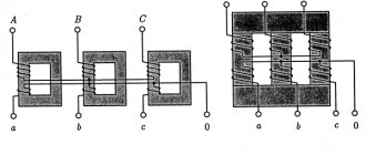
The core magnetic circuit is a U-shaped or W-shaped structure. It is assembled from rods pulled together by a yoke. To protect the coils from the influence of external electromagnetic forces, armored magnetic circuits are used. Their yoke is located on the outside and covers the rod with the coil. The toroidal type is made of metal strips. Due to their ring design, such cores are the most economically advantageous.
Knowing the shape of the core, it is easy to calculate the power of the transformer. It is found using a simple formula: P=(S/K)*(S/K), where:
- S is the cross-sectional area of the core.
- K is a constant coefficient equal to 1.33.
The area of the core depends on its type, its unit of measurement is a centimeter squared. The result obtained is measured in watts. But in practice, it is often necessary to calculate the core cross-section based on the required power of the transformer: Sc = 1.2√P, cm2. Based on the formulas, we can confirm the conclusion: that the greater the power of the product, the larger the core used.
Design (types) of pulse transformers
Depending on the shape of the core and the placement of coils on it, ITs are produced in the following designs:
The figures indicate:
- A – magnetic circuit made of transformer steel grades made using cold or hot metal rolling technology (with the exception of the toroidal core, it is made of ferrite);
- B – coil made of insulating material
- C – wires creating inductive coupling.
Note that electrical steel contains few silicon additives, since it causes power loss from the effect of eddy currents on the magnetic circuit. In toroidal IT, the core can be made from rolled or ferrimagnetic steel.
The plates for the electromagnetic core set are selected in thickness depending on the frequency. As this parameter increases, it is necessary to install thinner plates.
Calculation programs
There are many programs that offer online calculation of the parameters of any transformer with an armored or rod core. One of these could be the service on the “skrutka” website. To determine the characteristics, you will need to indicate a number of the following data:
- input voltage - U1;
- output voltage - U2;
- plate width - a;
- stack thickness - b;
- network frequency - Hz;
- overall power - V*A;
- efficiency;
- magnetic inductance of the magnetic circuit - T;
- current density in the windings - A/mm sq.
The last 4 values are tabular, so you will need to use a reference book.
It is necessary to competently and responsibly calculate the parameters of the transformer, because the quality of the functioning of your power supply will depend on the quality of the work performed. You shouldn't always rely on programs; they may contain errors. Select one or more parameters and recalculate them manually using the previously given formulas. If you get approximately the same value, then the result can be considered correct.
Calculation of initial data and selection of device elements
First of all, it is necessary to correctly select the most suitable magnetic circuit. Universal designs include armor cores with W-shaped and cup-shaped configurations. Setting the required gap between the parts of the core makes it possible to use them in any switching power supplies. However, if a half-bridge push-pull converter is being assembled, you can get by with a conventional ring magnetic core. When calculating, it is necessary to take into account the outer diameter of the ring (D), the inner diameter of the ring (d) and the height of the ring (H).
There are special reference books on magnetic cores, where the dimensions of the ring are presented in the KDxdxH format.
Before calculating a pulse transformer, it is necessary to obtain a certain set of initial data. First you need to decide on the supply voltage. There are some difficulties here due to possible... Therefore, for calculations, the maximum value of 220 V + 10% is taken, to which special coefficients are applied:
- The amplitude value is: 242 V x 1.41 = 341.22 V.
- Next 341.22 - 0.8 x 2 = 340 V minus the voltage drop across the rectifier.
The value of induction and frequency is determined using tables:
Manganese-zinc ferrites.
Options
| Ferrite grade |
Nickel-zinc ferrites.
| Options | Ferrite grade | |||||
| Cutoff frequency at tgδ ≤ 0.1, MHz | ||||||
| Magnetic induction B at Hm = 800 A/m, T | ||||||
Transformer calculation online
There is a transformer calculation formula that helps to calculate the power transformer. To make your life easier and avoid errors in calculations, you can use this program. It will allow you to design transformers for various voltages and powers very quickly and without problems. This is a very convenient calculator for radio amateurs and professionals. It will help not only calculate the transformer, but also help you study its structure and how everything works. This is the easiest and fastest way to calculate everything. To do this, you need to fill in all the information you know and press the button. It turns out that you need to press one button to calculate the transformer!
Advantages of an online calculator
As a result of calculating the transformer online, the output parameters are obtained in the form of power, current in amperes, number of turns and wire diameter in the primary and secondary windings.
There are formulas that allow you to quickly perform transformer calculations. However, they do not provide a complete guarantee against errors in calculations. To avoid such troubles, an online calculator program is used.
The results obtained make it possible to design transformers for various powers and voltages. Using the calculator, not only transformer calculations are carried out. There is an opportunity to study its structure and basic functions.
The requested data is inserted into the table and all that remains is to click the desired button.
Thanks to the online calculator, you do not need to carry out any independent calculations. The results obtained allow you to rewind the transformer yourself.
Most of the necessary calculations are carried out in accordance with the dimensions of the core. The calculator simplifies and speeds up all calculations as much as possible.
You can obtain the necessary explanations from the instructions and then strictly follow their instructions.
The design of transformer magnetic cores is represented by three main options - armored, rod and toroidal. Other modifications are much less common. To calculate each type, initial data is required in the form of frequency, input and output voltage, output current and dimensions of each magnetic circuit.
Typical parameter calculation
Quite often, radio amateurs use a simplified method when calculating a transformer. It allows you to perform calculations at home without using quantities that are difficult to know. But it’s easier to use an online calculator ready for calculating a transformer. In order to use such a calculator, you will need to know some data, namely:
- voltage of the primary and secondary windings;
- core dimensions;
- plate thickness.
After entering them, you will need to click the “Calculate” button or something similar in name and wait for the result.
Rod type magnetic core
If it is not possible to calculate on a calculator, performing such an operation yourself is not difficult and manually. To do this, you will need to determine the voltage at the output of the secondary winding U2 and the required power Po. The calculation proceeds as follows:
After the first stage is completed, proceed to the next stage of calculation. The number of turns in the primary winding is determined by the formula: K1 = 50*U1/S. And the number of turns of the secondary winding is determined by the expression K2= 55* U2/S, where:
- U1 - voltage of the primary winding, V.
- S—core area, cm².
- K1, K2 - number of turns in windings, pcs.
It remains to calculate the diameter of the wound wire. It is equal to D = 0.632*√ I, where:
- d — wire diameter, mm.
- I is the winding current of the calculated coil, A.
Experimental measurement of pulse transformer parameters.
For the sample, a ring of 3000NM ferrite of size K10x6x2 was taken. The primary winding was 21 turns, the secondary 14, transformation ratio n = 1.5, load resistance was 4.7 kOhm, the source was a rectangular pulse generator on TTL microcircuits with a level of 6V, a frequency of 1 MHz and an internal resistance ri ≈ 200 Ohm
.
Let's calculate the theoretical parameters: S c = 4 ⋅ 10 -6 m 2
, la = 25.13 ⋅ 10 -3 m,
AL theor = 600 nH / vit 2
,
L 1theor = 0.6 ⋅ 21 2 = 265 μH
,
Ls theor ≈ 265/3000 = 0.09 μH
,
C p theor ≈ 21+14 = 35 pF.
Reduced load resistance
R = n 2 Rн = 2.25 ⋅ 4.7 ~ 10 kOhm
.
Results of inductance measurements using the AKIP-6107 device: L 1 = 269 µH
,
L 2 = 118 μH
, short-circuiting the secondary winding we obtain
2Ls = 6.8 μH
, which is two orders of magnitude higher than its theoretical estimate.
The dynamic capacitance Cp can be estimated using formula (15) by applying rectangular pulses to the transformer and using an oscilloscope to measure the period of “ringing” oscillations at the pulse fronts at the output of the secondary winding. The “ringing” frequency fs turned out to be 18.5 MHz, which gives Cp ≈ 21 pF and is in good agreement with the theoretical estimate. For comparison with experiment, an equivalent circuit with measured parameters was simulated in the LT Spice program.
Fig.4. Transformer model. Vout is the reduced voltage, the actual one will be n times less.
Fig.5. Experiment results. The vertical scale is 1 volt per division.
So, the model built on the basis of measured L μ , L s and C p
is quite consistent with experiment. The theoretical capacitance estimate of 1 pF per turn for small rings is acceptable, but the leakage inductance estimate is two orders of magnitude different from the actual estimate. It is easier to determine it experimentally.
Appendix 1. Derivation of the formula for the number of turns.
When voltage U
induced emf E will appear on the winding in it
: U = -E = n Sc dB / dt
For a sinusoidal voltage with amplitude Um:
Um = n Sc ω Bm
Where does the number of turns come from n = Um / (Sc ω Bm)
Expressing the circular frequency in terms of the usual one, and the area in cm 2, we obtain the engineering formula: n = 0.16 ⋅10 4 / (f Bm Sc)
For a rectangular voltage of magnitude Um:
dB = dt Um / (n Sc)
Integrating over time from 0 to T/2 and taking into account that in half a period the field will change from -Bm to +Bm we obtain: 2Bm = (T / 2) Um / (n Sc)
Expressing the period in terms of frequency and the area in cm 2, we obtain the engineering formula: n = 0.25 ⋅10 4 / (f Bm Sc)
It is suitable for both cases.
Appendix 2. Derivation of the formula for the overall power of the transformer.
According to Faraday's law of electromagnetic induction, the relationship between the voltage on the coil and the change in magnetic induction in it:
U dt = n Sc dB
During the time from 0 to T/2, the induction will change from -Bm to +Bm, integrating within these limits we obtain:
U av = 4 n Sc Bm f
Where: $$ U_{cp}={2 \over T} \int_0^{T/2} U dt $$
But the devices do not measure the average, but the effective voltage, which is equivalent to constant energy. The relationship between the average and effective voltage gives the shape coefficient k f = U eff / U avg
. For a meander it is equal to 1, for a sine it is 1.11. Hence the effective voltage across the coil:
Ueff = 4 kf n Sc Bm f
We will estimate the overall power from the following considerations. The frequency f is not high, losses due to eddy currents and magnetization reversal are small, and the power is limited by winding overheating. It is determined by the maximum current density j, which is the same for both windings. Let us define the overall power as half the sum of the powers of the primary and secondary windings.
Pgab = (P 1 + P 2) / 2 = (U eff1 I 1 + U eff2 I 2) / 2 = j (S 1 n 1 + S 2 n 2) 4 kf Sc Bm / 2
where S 1 and S 2 are the turn areas of the primary and secondary windings.
This can be written in terms of copper area Sm:
Pgab = 2 kf f Sc Sm Bm j
The copper area is associated with the window fill factor σ = Sm / S 0 . Sigma is a certain empirical coefficient, equal to a minimum of 0.15 for a single-layer winding and a maximum of 0.4 for a multilayer winding (it won’t fit anymore). As a result, our formula looks like:
Pgab = 2 kf σ f Sc S 0 Bm j
All quantities here are in SI.
Let us assume that the voltage has the shape of a meander, k f = 1. By choosing the current density j = 2.2 A / mm 2, filling factor σ = 0.15, expressing the area in cm 2, Bm in T, frequency in Hz, we obtain the calculation formula :
Pgab = Sc S 0 f Bm / 150
As you can see, this formula was derived with a large margin; in fact, you can get more power from a transformer.
Network transformer calculation
- If you have a certain transformer core from which you need to make a transformer, then you need to measure the core (as shown in the figure), and also measure the thickness of the plate or tape.
- The first step is to calculate the cross-sectional area of the core - Sc (cm²) and the cross-sectional area of the window - So (cm²).
- For a toroidal transformer:
- Sc= H * (D – d)/2
- S0= π * d2/ 4
For W and P-shaped core:
Let's determine the overall power of our core at a frequency of 50 Hz:
- η is the efficiency of the transformer,
- Sc is the cross-sectional area of the core, cm2,
- So is the cross-sectional area of the window, cm2,
- f is the operating frequency of the transformer, Hz,
- B—magnetic induction, T,
- j is the current density in the winding wire, A/mm2,
- Km is the filling factor of the core window with copper,
- Kc is the coefficient of filling of the core section with steel.
When calculating a transformer, it is necessary to take into account that the overall power of the transformer must be greater than the calculated electrical power of the secondary windings.
The initial initial data for the simplified calculation are:
- primary winding voltage U1
- secondary winding voltage U2
- secondary winding current l2
- power of the secondary winding P2 = I2 * U2 = Pout
- core cross-sectional area Sc
- window cross-sectional area So
- transformer operating frequency f = 50 Hz
The efficiency (η) of the transformer can be taken from the table, provided that Pout = I2 * U2 (where I2 is the current in the secondary winding, U2 is the voltage of the secondary winding), if there are several secondary windings in the transformer, which is considered Pout each and then they are added.
B - magnetic induction is selected from the table, depending on the design of the magnetic circuit and Pout.
j is the current density in the winding wire, also selected depending on the design of the magnetic circuit and Pout.
Km - fill factor of the core window with copper
Kc is the coefficient of filling of the core section with steel
Fill factors for plate cores are indicated in parentheses when the plates are insulated with varnish or phosphate film.
During the initial calculation, it is necessary to comply with the condition - Pgab ≥ Pout; if this condition is not met, then during the calculation, reduce the current or voltage of the secondary winding.
Once you have decided on the overall power of the transformer, you can begin to calculate the voltage of one turn:
- where Sc is the cross-sectional area of the core, f is the operating frequency (50 Hz), B is the magnetic induction selected from the table, depending on the design of the magnetic core and Pout.
- Now we determine the number of turns of the primary winding:
- w1=U1/u1
- where U1 is the voltage of the primary winding, u1 is the voltage of one turn.
- The number of turns of each of the secondary windings is found from a simple proportion:
- where w1 is the number of turns of the primary winding, U1 is the voltage of the primary winding, U2 is the voltage of the secondary winding.
- Let's determine the power consumed by the transformer from the network, taking into account losses:
- Р1 = Рout / η
- where η is the efficiency of the transformer.
- We determine the current value in the primary winding of the transformer:
- I1 = P1/U1
- We determine the diameters of the wires of the transformer windings:
- d = 0.632*√ I
- where d is the wire diameter, mm, I is the winding current, A (for the primary and secondary windings).
How to determine the number of turns of the secondary winding?
To calculate the number of turns of the secondary winding, you need to know how many turns there are per volt. If the number of turns of the primary winding is unknown, then this value can be obtained using one of the methods suggested below.
First way.
Before removing the secondary windings from the transformer frame, you need to measure the mains voltage and the voltage on one of the longest secondary windings at idle (without load). When unwinding the secondary windings, you need to count the number of turns of the winding on which the measurement was made.
Having this data, you can easily calculate how many turns of wire are per volt of voltage.
Second way.
This method can be used when the secondary winding has already been removed and the number of turns has not been counted. Then you can wind 50-100 turns of any wire as a secondary winding and make the necessary measurements. The same can be done if a transformer is used that has only a few turns in the secondary winding, such as a spot welding transformer. Then the temporary measuring winding will significantly increase the accuracy of calculations.
Once the data is received, you can use a simple formula:
ω1 / U1 = ω 2 / U2
ω 1 – number of turns in the primary winding,
ω 2 – number of turns in the secondary winding,
U1 – voltage on the primary winding,
U2 – voltage on the secondary winding.
Example:
I got hold of this transformer without a secondary winding or identification marks.
I wound it as a temporary secondary winding - 100 turns.
I wound this winding with a thin wire, which I don’t mind and which I have most of. I wound it “in bulk”, which means haphazardly.
Test results.
The network voltage during measurement is 216 Volts.
The voltage on the secondary winding is 20.19 Volts.
Determine the number of turns per volt at 216V:
100 / 20.19 = 4.953 vit./Volt
Here you should not skimp on accuracy, since the error accumulates during measurements. Fortunately, we don’t count on paper.
We calculate the number of turns of the primary winding:
4.953 * 216 = 1070 vit.
Now you can determine the number of turns per volt at 220V.
1070 / 220 = 4.864 vit./Volt
We calculate the number of turns in the secondary windings.
For my transformer I need to calculate three windings. Two identical “III” and “IV” at 12.8 Volts and one “II” at 14.3 Volts.
4.864 * 12.8 = 62 vit.
4.864 * 14.3 = 70 vit.
Return to top menu
Calculation of a three-phase transformer
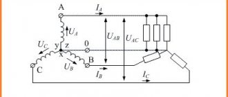
Manufacturing a three-phase transformer and its precise calculation is a more complex process, since here the primary and secondary windings already consist of three coils. This is a type of power transformer, the magnetic circuit of which is most often made using the rod method. Here such concepts as phase and linear voltages already appear. Linear ones are measured between two phases, and phase ones between a phase and ground. If a three-phase transformer is designed for 0.4 kV, then the linear voltage will be 380V, and the phase voltage 220V. The windings can be connected in a star or triangle, which gives different values of currents and voltages.
The windings of a three-phase transformer are located on the rods in the same way as in a single-phase one, i.e., the low voltage LV windings are placed closer to the rod, and the higher voltage HV windings are located on the lower voltage windings.
High-voltage three-phase current transformers are calculated and manufactured exclusively in industrial conditions. By the way, any step-down transformer, when switched back on, acts as a voltage-increasing device.
Transformer power concept
An AC transformer does not produce electrical energy, but only converts it in magnitude. Therefore, its power completely depends on its load (current consumption) of the secondary circuit. If there are several consumers, the total load that can be connected simultaneously must be taken into account. For AC circuits, the active and reactive nature of consumption is taken into account.
We recommend reading: Do-it-yourself repair of PC power supplies: step-by-step pinout, starting the power supply from a computer
Active
This component of the characteristic is defined as the average instantaneous value over a certain period of time. For sinusoidal alternating current circuits, the value of the oscillation period is used as a period of time:
T=1/f,
where f is frequency.
The active part depends on the nature of the load, that is, on the phase shift between current and voltage and is determined by the formula:
P=i∙U∙cosϕ,
where ϕ is the phase shift angle.
The active component of AC devices is expressed in Watts, as for DC circuits.
Reactive
A reactive load differs from an active load in that during one period of voltage fluctuations, electrical energy is not actually consumed, but is returned. As a result of the fact that devices with large capacitance or inductance (electric motors) are connected to the power supply device, a phase shift occurs between the current and voltage.
The reactive component of consumption is determined by the expression:
Q= i∙U∙sinϕ
The unit of measurement is var (volt-ampere reactive).
Full
The total power of the transformer takes into account all consumed and returned energy and is found from the expression:
S= i∙U
All components are related by the relationship:
S2=P2+Q2.
The unit of measurement is VA (volt-ampere).
Apparent power equals active power only in the case of a fully active load.
Nominal
The rated power of the transformer takes into account the possibility of operation of the structure, taking into account the connection of consumers of different types, that is, it is similar to the full one. At the same time, proper operation of the device is guaranteed for the entire declared service life under the specified operating conditions.
Rated power, like total power, takes into account the active and reactive nature of consumption, which can change during operation.
Expressed in volt-amperes.
How to calculate and wind a low-frequency power transformer for a ULF power supply?
This topic arose in connection with writing an article about a homemade low-frequency amplifier. I wanted to continue the story by talking about the power supply and adding a link to some popular article about rewinding transformers, but I couldn’t find a simple, understandable description. What can you do, you need to do everything yourself. https://oldoctober.com/
In this opus I will tell you, using my design as an example, how to calculate and wind a power transformer for ULF. All calculations were made using a simplified method, since in the vast majority of cases, radio amateurs use ready-made transformers. The article is intended for beginner radio amateurs.
How to determine the required power of a power transformer to power the ULF?
I decided to build a simple amplifier with a power of 8-10 watts per channel, using the cheapest microcircuits that I could find on the local radio market. They turned out to be TDA2030, priced at only $0.38.
The estimated load power should be 8-10 watts per channel:
10 * 2 = 20W
The efficiency of the TDA2030 chip according to the datasheet is 65%.
20 / 0.65 = 31W
I selected a transformer with a twisted armored magnetic core, so the efficiency can be assumed to be 90%. https://oldoctober.com/
31 / 0.9 = 34W
You can roughly estimate the efficiency of the transformer using the table
| Transformer power (W) | Transformer efficiency (%) | |||
| Armor stamped | Armor twisted | Core twisted | Annular | |
| 5-10 | 60 | 65 | 65 | 70 |
| 10-50 | 80 | 90 | 90 | 90 |
| 50-150 | 85 | 93 | 93 | 95 |
| 150-300 | 90 | 95 | 95 | 96 |
| 300-1000 | 95 | 96 | 96 | 96 |
This means that you will need a network transformer with a power of about 30-40 Watts. Such a transformer should weigh about a kilogram or a little more, which, in my opinion, will add stability to my mini amplifier and it will not “run” after the cords.
Calculation of a transformer for a flyback switching power supply (Flyback)
The popularity of flyback power supplies (Flyback) has recently increased greatly due to the simplicity and low cost of this circuit solution - on the market you can often find integrated circuits that include almost the entire high-voltage part of such a source; the user only has to connect the transformer and assemble the low-voltage part according to standard schemes. There is also a large amount of software available for calculating transformers, ranging from universal programs to specialized software from integrated circuit manufacturers. Today I want to talk about manual calculation of a pulse transformer. “Why is this necessary?” the reader may ask. Firstly, manual calculation of a transformer implies a complete understanding of the processes occurring in the power source, which often does not happen if a novice radio amateur calculates a transformer in special software. Secondly, manual calculation allows you to select the optimal parameters for the functioning of the source (and have an idea of which parameter needs to be changed in which direction to achieve a given result) even at the development stage. So, let's begin. The block diagram of the OIP is shown in Fig. 1. It consists of the following main functional units: switch Sw, transformer T1, output voltage rectifier VD1 and C2, high-frequency interference filter C1 and snubber Snb.
Rice. 1
Such a source operates as follows (see simplified graphs in Fig. 2): at the initial time t0, the switch Sw opens, supplying the input voltage Uin to the primary winding of transformer T1. At this time, the voltage at the lower terminal of winding I (point a) is zero (relative to the negative wire of the input voltage), the current begins to increase linearly in winding I, and a voltage proportional to the transformation ratio T1 (UoutInv) appears on winding II. But the polarity of this voltage turns out to be negative (at the top terminal of winding II in the diagram, point b), therefore the diode VD1 is closed and the voltage does not pass to the output capacitor C2. Over the interval Ton (from t0 to t1), the current through the winding I increases linearly to the value Imax, and the energy is stored inside the transformer T1 in the form of a magnetic field.
Rice. 2
At time t1, the switch Sw closes sharply, the current through winding I stops and a self-induction emf appears in it, directed so as to continue the stopped current. At this moment, winding I itself becomes a voltage source. This happens because the energy in the inductor is stored in the form of current (in fact, in the form of a magnetic field, but it is proportional to the current through the coil, so the formula for energy in the coil is A = LI²/2), but according to the law of conservation of energy, it cannot disappear without a trace, it must go somewhere. Consequently, the current in the coil cannot stop instantly, so the coil itself becomes a source of voltage, and of any amplitude (!) - such as to ensure the continuation of the same current Imax immediately after closing the key. This is the first important feature of an inductor that should be remembered - when the current in the coil suddenly stops, it becomes a source of voltage of any amplitude, trying to maintain the current that has stopped in it, both in direction and in amplitude
. What exactly is “any” amplitude? Large enough to, for example, damage a high-voltage switch or create a spark in a car's spark plug (yes, it uses exactly this property of inductance coils to ignite a car).
Everything described above would have happened if winding I was the only winding of transformer T1. But it also contains winding II, inductively coupled to I. Therefore, at time t1, an EMF also appears in it, directed so that at point b there is a plus in relation to the ground. This EMF opens diode VD1 and begins to charge capacitor C2 with current I2max. Those. The charge of capacitor C2 and the transfer of energy to the load occurs at the moment in time when the switch Sw is closed. That is why power supplies built on this principle are called flyback - because there is no direct transfer of energy from the high-voltage part to the low-voltage part, the energy is first stored in the transformer and then given to the consumer
.
In the time interval from t1 to t2, the current I2 of the secondary winding, linearly decreasing from I2max to 0, maintains the magnetic field inside the coil in accordance with the law of conservation of energy and does not allow the voltage on the primary winding (since they are inductively coupled) to rise to an uncontrolled value. The voltage on winding I at this moment becomes equal to the output voltage multiplied by the transformation ratio T1. However, the polarity of this voltage is such that it is added to the input voltage Uin and applied to the private switch Sw. Those. A voltage greater than the input voltage is applied to the private switch Sw! This is also an important feature of the IIP that should be remembered.
At time t2, the energy stored in transformer T1 ends, diode VD1 closes, the voltage at point b becomes zero, at point a – the input supply voltage, and all processes in the circuit stop until time t3, when the entire cycle is repeated from the very beginning. At the same time, in the time intervals t0-t1 and t2-t4, the load is powered exclusively by the energy stored by the output capacitor C2
.
The described operating mode of the OIP is called the breaking current mode - i.e. during the interval Toff (t1-t3), all the energy stored in transformer T1 is transferred to the load, therefore, at time t3, the current through the primary winding I begins to increase from zero. There is also a mode of continuous currents, when at the moment t3 some part of the energy still continues to be in the transformer T1, and the current through winding I at the moment t3 does not start from a zero value. This mode has its own characteristics, advantages and disadvantages, which we will talk about next time.
So, what are the main features of the OIP in the breaking current mode? Let's write down the main points:
- The transfer of energy from the source to the consumer in the OIP does not go directly; the energy is first stored in the transformer and then transferred to the load. This uniquely determines the phasing of the primary and secondary windings, and also forces the use of only a half-wave rectifier at the output of the unit. This also implies implicit conclusion 2, which, as my personal practice has shown, unfortunately, even fairly experienced power supply designers do not fully understand.
- The maximum power that the OIP can deliver to the load, among other things, is limited by the maximum amount of energy that the transformer can store! And this, in turn, is determined by the design features of the core and does not depend on the windings and the number of their turns (below in the article I will consider this “paradox” separately and provide mathematical proof). This feature limits the use of OIP where large output powers are needed.
- The low-voltage OIP circuit consists of a diode, a capacitor and, possibly, additional filter elements. However, in OIP the diode is always the first, then the capacitor comes and nothing else.
- In the steady-state operating mode of the OIP, the amount of energy received by the primary winding I of transformer T1 during the time Ton is equal (without taking into account losses) to the amount of energy given by winding II during the time Toff. Since the rate at which the coil receives or releases energy is determined by the voltage across it, the relationship between the “charge” and “discharge” voltages is determined precisely by the intervals Toff and Ton. That is, in fact, in the most complex operating mode of the unit, the Duty cycle (fill factor, D), equal to Ton/(Ton + Toff) determines the ratio of the reverse voltage on winding I to the supply voltage Uin. This point will be explained in more detail below.
- According to the law of conservation of energy, the current I2max given by winding II to the load at time t1 is numerically equal to the current Imax just flowing in the primary winding, multiplied by the ratio of the number of turns in winding I to the number of turns in winding II (explanation below).
- The pulse value of the current I2max significantly exceeds the average output current of the power supply (2.5 or more times), therefore, significant power can be dissipated on the rectifier diode VD1. It is this feature that limits the use of OIP where large output currents are needed.
- The same (high pulse current value) applies to secondary winding II.
- The reverse voltage on diode VD1 is several times higher than the output voltage. This is due to the fact that usually the reverse voltage on the primary winding (which is forward for the diode) is selected several times lower than the input, so the input (which is reverse for the diode) after transformation turns out to be several times higher than the output.
Explanation to point 4. From physics we remember the formula for the inductor:
U(t) = L*(dI(t)/dt)
,
which means that the voltage across the coil is directly proportional to its inductance multiplied by the rate of change of current in it. What does this give us? First of all, if we apply a constant voltage U to the coil, then the rate of change of the current in it is constant. This allows us to rewrite the formula for constant voltage without differentials:
U = L*(ΔI/Δt)
,
and it is in accordance with this formula that the current graphs in Fig. 2 straight. Further, if we apply voltage Uin to the coil for a time Ton, the current in it will increase to the value
Imax = Uin*Ton/L
Now we want (in the most loaded operating mode) that all the energy of the coil that we just gained will be transferred to the load in the interval Toff, i.e. at time t3, the current in the coil should drop to zero. Here, for simplicity, we will imagine that we both supply and remove voltage/current from the same coil I; later I will explain why such an assumption is possible. Let’s calculate to what voltage we can “discharge” the coil so that the current reaches zero at time t3:
Udis = L*Imax/Toff
,
Let's substitute and simplify:
Udis = L*Uin*Ton/(L*Toff) = Uin*Ton/Toff
Those. the voltage by which we must “discharge” the coil at the moments of closing the switch Sw depends only on the input voltage and the “charge”-“discharge” intervals. Let us recall the formula for fill factor D:
D = Ton/(Ton + Toff),
Thus:
Udis = Uin*D/(1 – D)
But the voltage to which we “discharge” the coil is the reverse voltage that appears in the primary winding when the key is closed. Those. we found that it depends only on the input voltage and duty cycle D and is determined by the formula:
Uinv = Uin*D/(1 – D)
In real-world operation, the duty cycle value D will vary depending on the input voltage and power supply load. D will take its maximum value at the minimum input voltage and maximum output power - this operating mode is considered the most difficult, and this maximum value of D is set when designing the unit. What will happen at those moments when the input voltage of the unit is higher or the load is incomplete? D will take smaller values, because from a higher voltage, energy will be “stored” faster in the primary winding, or (in the case of a lower load) you simply need to “store” less energy. In any case, the reverse voltage on the primary winding will always be the same, because it is rigidly connected to the output voltage, and this, in turn, is stabilized by the circuit. So, the maximum reverse voltage on the switch is:
Usw = Umax + Umin*D/(1 – D)
This is an important point when designing EIP, because Usually the maximum reverse voltage on the switch is the initial parameter, i.e. the maximum duty cycle D is also a reference value
. In practice, the following maximum D values are usually used: 25% (1/4), 33% (1/3) and less often 50% (1/2). As you understand, in the latter case, the maximum reverse voltage on the switch will be equal to twice the minimum input voltage, which complicates the choice of semiconductor device. Lower maximum values of D, in turn, reduce the maximum power at the same current Imax, complicate the process of controlling the switch Sw and reduce the stability of the unit.
Why did we apply the assumption here that we both supply energy and remove it from the primary winding I, and what will happen in reality when energy is removed from coil II? The same. The voltage at the terminals of any transformer winding is proportional to the rate of change of the magnetic field in the core (and the field is proportional to the current, so the voltage is proportional to the rate of change of current). Therefore, it does not matter from which winding we remove energy, if we do it at the same speed, the magnetic field in the transformer will decrease equally, and there will be the same voltage at the terminals of the primary winding. But to what voltage should the secondary winding be “discharged” so that energy is removed at the same speed? To do this, first consider the current in the secondary winding.
Explanation to paragraph 5. Let winding I have N1 turns, while winding II has N2. The magnetic field is created by the current passing through each turn of the coil, i.e. it is proportional to the product I*N. Then, we obtain Imax*N1 = I2max*N2 (based on the fact that both windings are wound under absolutely identical conditions), hence the initial current of the secondary winding:
I2max = Imax*N1/N2
So, the current in the secondary winding will be N1/N2 times higher than in the primary. But at what voltage should we “discharge” the secondary winding in order to spend all the energy stored in the transformer by time t3? Obviously, we must do this at exactly the same speed; those. at each individual moment in time the transformer will lose the same energy value dA(t). But in the first case dA(t) = Udis*I1(t)*dt (obtained from A = W*T, W = U*I), and now it will be dA(t) = Uout*I2(t)*dt . Let's equate these two functions:
Uout *I2(t) = Udis*I1(t), therefore, at the very beginning of the “discharge” the instantaneous discharge powers should be equal to:
Uout*I2max = Udis*Imax,
Uout = Udis*Imax/I2max = Udis*Imax/(Imax*N1/N2) = Udis*N2/N1
Those. in order to spend all the energy of the transformer by time t3, we must “discharge” the secondary winding II to the voltage Udis*N2/N1, while the discharge current will fall linearly from Imax*N1/N2 to zero. Thus, we have established a relationship between the output voltage of the unit, the number of turns in the windings and the reverse voltage on the primary winding of the transformer.
This is where the purely theoretical part ends, and we can move on to practice. The first question that most likely arises in the reader’s mind at the moment is where to even start developing IIP? Below I will give the recommended sequence of steps. Let's start with a situation where the transformer is planned to be manufactured completely independently (there are no strict restrictions on it).
- We determine the output voltages and currents of the power source.
- We increase the output voltage by the amount that drops across the rectifier diodes (VD1). It is best to use reference information, but as a first approximation you can take 1V for conventional silicon diodes and 0.3V for Schottky diodes. Particular accuracy should be observed when the OIP has several output windings with different voltages, because It is possible to stabilize the voltage on only one of them.
- We calculate the total output power of the transformer.
- We consider the calculated input power of the block as Pin = Pout/0.8 (here the block efficiency is taken to be 80%).
- We determine the conversion frequency F. Usually the frequency is selected from 20KHz to 150KHz. Frequencies below 20KHz can be heard by the human ear (the unit will “squeak”), frequencies above 150KHz impose more serious restrictions on the element base, and switching losses of semiconductors (switches and diodes) also increase. Increasing the conversion frequency makes it possible to reduce the dimensions of the transformer; the most common frequency range for OIP is from 66 to 100 kHz.
- We calculate the maximum input voltage from which we will have to work. It is usually calculated as the rectified mains voltage +20%, i.e. Umax = Unetwork*1.7 (391V for 230V network). The input filter capacitor must also be designed for this voltage (at least 400V in this case).
- We calculate the minimum input voltage from which we will have to work. It is usually calculated as the minimum permissible operating voltage -20%, minus the voltage drop across the filter capacitor during the half-cycle of the input voltage. For a 230V network and the capacitance of the input filter capacitor at a rate of at least 1 microfarad per 1 watt of load, you can take (on average) the value Umin = 220V. If we imagine that the voltage on the capacitor does not drop at all from one half-cycle of the input voltage to the other, then Umin can be taken as 260V.
- We determine the duty cycle D based on the maximum permissible reverse voltage on the switch (calculated using the formula Uinv = Umax + Umin*D/(1 – D)).
- We calculate the amount of energy that needs to be transferred to the secondary winding in one pulse: Aimp = Pin*1s/F = Pin/F.
- We solve the system of equations for the heaviest operating mode: A = LImax²/2, Umin = LImax*F/D, we obtain L = Umin²*D²/(2*Aimp*F²), Imax = Umin*D/(L*F) – this will be the required inductance of the primary winding and the maximum current flowing through it.
- Based on the obtained Imax, we select a key.
- If Imax turns out to be slightly larger than the existing (selected) switch can provide, we change the initial parameters - increase D (as much as possible based on the permissible reverse voltage of the switch), increase the capacitance of the filter capacitor to increase Umin. At first glance it may seem surprising, but the maximum current in the primary winding does not depend on frequency - if we plug everything into the formulas, we get Imax = 2*Pin/(Umin*D). Based on this formula, it was possible to calculate the maximum current at step 8 (immediately after choosing D), but it would be difficult to explain where such a calculation came from.
- If the Imax value still turns out to be greater than the permissible value and there is no way to increase it, you should consider the design of the OIP in the continuous current mode.
- Based on the required inductance of the primary winding and the maximum current in it, we select the transformer core, calculate the required gap and the number of turns of the primary winding (formulas will be later in the article).
- Using the formula N2 = Uout*N1*(1 – D)/(Umin*D) we calculate the number of turns of the secondary winding.
- We determine the root-mean-square value of the currents in the transformer windings using the formula Irms = Imax*SQRT(D/3), based on which we calculate the diameter of the wire required for winding. Most often, switching power supplies use a current density of 2 to 5 A/mm².
- We wind the transformer according to all the rules for winding transformers for OIP.
- In order to ensure that the winding is correct, we measure the inductance of the primary winding.
Now let's take a little look at the transformer itself and its design. Traditionally, for switching power supplies, the transformer is made on some kind of core made of a material with high magnetic permeability. This allows, with the same number of winding turns, to greatly increase their inductance, i.e. reduce the number of turns to achieve a given inductance, and, consequently, reduce the dimensions of the winding. However, the use of a core also adds disadvantages - due to magnetic hysteresis, some energy is lost in the core, the core heats up, and losses in the core increase with increasing frequency (another reason why the conversion frequency cannot be greatly increased). Also, the addition of a core introduces a new, previously unspoken limitation - the maximum permissible magnetic induction flux density Bmax. In practice, this manifests itself in the fact that if you increase the current through the winding, at a certain point in time, when the current reaches a certain maximum value, the core will enter saturation and a further increase in current will not cause the same increase in magnetic flux as before. This, in turn, will cause the "relative inductance" of the winding to drop sharply, which will cause the current through it to build up even faster. In practice, if you do not provide protection for the OIP switch Sw from the core entering saturation, the switch will simply burn out from overcurrent
. Therefore, in all OIP circuits, with the exception of the simplest blocking generators, current control through the switch Sw and early closing of the key is used when the maximum permissible current through the primary winding is reached.
How large is this maximum value of the magnetic flux density? For the most common core material - ferrite - it is considered equal to 0.3T. This is an average value, it may differ for each specific material, so it is a good idea to consult a reference book here. Also, it depends on the temperature of the core and, as you probably already guessed, falls as it increases. If you are designing an OIP intended to operate in extreme conditions, where core temperatures can reach up to 125 degrees, reduce Bmax to 0.2T.
The basic formula that you will have to use when calculating transformers is the inductance of the winding according to its dimensions:
L = (μ0*μe*Se*N²)/le
, Where
μ0 – absolute magnetic permeability of vacuum, 4πе-7, μe – effective magnetic permeability of the core, Se – effective cross-sectional area of the magnetic core, m². N – number of turns le – length of the average magnetic line of the core, m
Magnetic induction flux density in the core:
B = (μ0*μe*I*N)/le
, Where
I – current through the winding, A
Thus, based on the maximum permissible magnetic induction flux density, the maximum permissible current for the winding will be equal to:
Imax = (Bmax*le)/(μ0*μe*N)
And now another very important point - in practice, if we substitute the real data of the transformer into the above formulas, it turns out that the maximum permissible current in the primary winding turns out to be several times less than what we need! Those. the core will be brought into saturation even before we can “pump” the required energy Aimp into it. So what should we do, not increase the dimensions of the transformer to indecent values?
No. It is necessary to introduce a non-magnetic gap into the core! The introduction of a non-magnetic gap greatly reduces the effective permeability of the core, allowing significantly more current to pass through the windings. But, as you understand, this will require a larger number of turns to achieve the required winding inductance.
Let's consider the formulas for a core with a gap. Effective magnetic permeability of core with gap:
μe = le/g
, Where
g – total thickness of the gap, m.
It should be noted that this formula is valid only if the resulting μe is much less than the initial magnetic permeability (several times), and g is much less than the cross-sectional dimensions of the core. So, consider the formula for the inductance of a winding on a core with a gap:
L = (μ0*Se*N²)/g
The introduction of the gap only made the formula simpler. Maximum permissible current through the winding:
Imax = (Bmax*g)/(μ0*N)
Well, the last formula, which you can derive yourself. Gap size for given current:
g = (I*μ0*N)/Bmax
Now let's make an interesting conclusion. As you remember, the energy stored in the coil is expressed by the formula A = LI²/2. So what is the maximum energy that can be stored in some abstract core? Let's substitute the data into the formulas.
Amax = (μ0*Se*N²)*(Bmax*g) ²/((μ0*N) ²*2g) = Se*g*Bmax²/2μ0
Now you may be surprised, but the maximum energy that can be stored in a core does not depend on what windings are wound on it! But this is logical, because energy is expressed in a magnetic field, and the windings only allow it to be changed in one direction or another! The number of turns in the windings only determines the speed at which the magnetic induction can reach its maximum value for a given applied voltage, but this maximum value is determined only by the design of the core!
This conclusion is of great importance when designing OIP on standardized cores
. If you are faced with just such a task, then, first of all, you need to calculate what maximum amount of energy the selected core can “absorb” in one pulse in order to understand whether it is suitable for your block power. As you understand, in this case, the maximum power of the block can be increased only by increasing the conversion frequency - the more often we pump energy Amax from the input to the output, the greater the power of the block as a result we can obtain.
Also, from the resulting formula it is clear that the amount of energy that can “fit” in the core is directly proportional to the non-magnetic gap! This allows the use of small cores at high powers by increasing the gap in them. The only limitation now will be the physical dimensions - an increase in the gap causes a decrease in the magnetic permeability, which requires a larger number of turns.
Now let's return to the block diagram of the OIP in Fig. 1. There are two blocks left in it, which I didn’t say anything about - capacitor C1 and snubber Snb.
The purpose of capacitor C1 is to ground the output part of the unit at high frequencies. The fact is that any transformer, even one wound according to all the rules with screens, has some kind of interwinding capacitance. A rectangular high-frequency voltage of enormous amplitude from point a passes through this capacitance to the output circuits of the block. Capacitor C1, which has a capacity much larger than the capacity of transformer T1, grounds the output of the unit at high frequencies. The capacitance value of this capacitor in the OIP is most often chosen in the region of 2 nf, the voltage is about a kilovolt. If the unit output is supposed to be strictly grounded (for example, only a grounded socket is used), C1 can be omitted.
The need for the Snb Snubber also stems from the imperfection of the T1 transformer, but of a completely different kind. Despite the fact that windings I and II are inductively coupled to each other, this connection is not 100%. In OIP circuitry, it is customary to say that winding I consists of two parts connected in series, where the first is completely inductively coupled to winding II, and the second is completely isolated from it. This second part of winding I is called "leakage inductance".
When at moment t1 the current in the primary winding (both parts of it) abruptly stops, the leakage inductance also tries to continue it. And since it is not connected to any other winding, it generates a high-voltage pulse applied to the private switch Sw. The energy of this pulse is many times less than the useful energy of Aimp (the better the transformer, the less it is in general), but it may be enough to damage the switch (in the case of a bipolar transistor, for example, it is quite enough for an avalanche breakdown). To protect the key from this impulse, it is extinguished using a special circuit design.
Rice. 3
The simplest option is an RCD snubber made of a diode, capacitor and resistor (see Fig. 3). The reverse voltage arising on winding I opens the diode VD and begins to charge capacitor C. As a result, all the pulse energy is transferred to the capacitor. In the intervals between pulses, the capacitor is discharged through resistor R. I.e. the energy removed from the leakage inductance ultimately turns into heat on the resistor R, so the power of this resistor must be significant (reaches several watts). The advantage of the snubber is its circuit simplicity, and the fact that part of the energy from capacitor C can be pumped back into transformer T using a slow diode VD, but these processes are already somewhat more complex than our simple article. The main disadvantage of a snubber is that its useful power also decreases! After all, the operating reverse voltage of the primary winding Vinv also charges the capacitor to this value, i.e. useful power Uinv²/R is wasted.
A circuit solution that does not have this drawback is a suppressor. It is a series-connected fast diode VD1 and a powerful and fast zener diode VD2. When the leakage inductance generates its high-voltage pulse, it opens the diode VD1, breaks through the zener diode VD2 and the pulse energy is dissipated on it. Zener diode VD2 is selected with a higher breakdown voltage than the reverse voltage Uinv, so it does not dissipate the useful power of the unit. The disadvantages of the suppressor include a higher level of electromagnetic interference associated with the sudden opening and closing of semiconductor devices.
What will happen if this high-voltage impulse is not extinguished by anything? In the case of a bipolar switch, most likely, an avalanche breakdown will occur in it and the power supply will go into boiler mode. Modern field-effect transistors are resistant to avalanche breakdown and allow a certain amount of energy to be dissipated at the drain (this is described in the documentation), so such a transistor can operate without a snubber or suppressor - its role will be performed by the transistor itself. Moreover, I have seen some cheap Chinese power supplies that did this. However, I strongly do not recommend this mode of operation, because... it further reduces the reliability of the unit. A suppressor diode (zener diode) is very cheap and is designed for colossal pulse powers (600W, 1.5KW), so why not use it for its intended purpose?
Another conclusion also follows from the above. Regardless of whether you decide to use a snubber or a suppressor, the reverse voltage on the private switch will be even higher than the operating calculated value Usw! This should be kept in mind when choosing a key.
Typically, modern key transistors and microcircuits have a permissible reverse voltage of 600 - 800 volts. At Umax = 391V, Umin = 220V, the reverse voltage on the switch Usw will have the following values (depending on D): D = 25%, Usw = 464V; D = 33%, Usw = 501B; D = 50%, Usw = 611B. This means that for switches with a maximum reverse voltage of 600V, only D = 33% or less should be selected. For keys with a reverse voltage of 700V, you can select D = 50%.
Well, at the end of the article I will give a simple example of calculating the EIP. Let's say we want to make a simple power supply that allows us to get 12V 1A at its output. Let's calculate it point by point:
- The output of the block is 12V 1A.
- Before the output diode (we will use a regular silicon one) there should be 13V.
- The output power of the transformer is 13W.
- Estimated input power of the block Pin = 13/0.8 = 16W.
- F = 100 kHz.
- Umax = 391V.
- Umin = 220V (input filter capacitor capacity – 22 µF).
- D = 33%, Uinv = 110V, Usw = 501V. We will focus on keys with a reverse voltage of 600V.
- Aimp = 16/100000 = 1.6e-4J = 160µJ.
- L = 1.65e-3H = 1.65mH, Imax = 0.44A
- We select the core, calculate the winding parameters and gap.
And now, for comparison, let’s calculate the same OIP for the case when the permissible network voltage can be in the range of 85-230V. What will be the differences?
- Umax = 391B
- Umin = 85V (the capacitance of the filter capacitor will need to be increased to 47 µF)
- D = 60%, Uinv = 128V, Usw = 519V, We will focus on switches with a reverse voltage of 600V.
- Aimp = 16/100000 = 1.6e-4J = 160µJ.
- L = 813 µH, Imax = 0.63 A
Please note that the parameters of the maximum current through the switch have not changed so significantly - from 0.44A to 0.63A, the inductance has dropped by half, but the range of permissible input voltages has expanded very significantly.
This is another advantage of OIP - the ease of creating power supplies operating from a wide range of input voltages. Perhaps this article does not fully consider all the nuances of constructing an IIP, but its volume turned out to be larger than planned. But nevertheless, I hope that it can help novice radio amateurs understand the principles and create flyback power supplies on their own.
Which ULF power supply circuit should you choose?
To power the microcircuit, I decided to use bipolar power.
With bipolar power supply, there is no need to deal with background noise and clicks when turned on. In addition, there is no need for coupling capacitors at the amplifier output.
Well, and most importantly, microcircuits designed for unipolar power supply and having a commensurate level of distortion are several times more expensive.
This is the power supply diagram. It uses a bipolar full-wave rectifier, which requires a transformer with two completely identical windings “III” and “IV” connected in series. Further, all basic calculations will be carried out only for one of these windings.
Winding “II” is designed to power electronic volume, tone and stereo controls assembled on the TDA1524 chip. I think I will describe the tone block in one of the future articles.
The current flowing through winding “II” will be extremely small, since the TDA1524 microcircuit at a supply voltage of 8.5 Volts consumes a current of only 35 mA. So the consumption here is expected to be less than one Watt and will not greatly affect the overall picture.