Device for testing electric motor rotors (armatures)
Haven't purchased one yet? Then let me introduce a homemade device for testing the rotor of electric motors, which was made due to the need to test various equipment such as drilling machines, grinders and washing machines, vacuum cleaners and so on. Of course, there are special devices on sale for performing such checks, but buying such a device is pointless, because assembling it yourself does not cost a penny.
Microchip PIC16F687 MCP1700
After a power tool arrives for repair, task No. 1 is to determine what is broken. As a rule, the tool fails due to the death of the armature or stator or both as a result of brutal exploitation. There are two main faults: 1 – winding short circuit (armature or stator), 2 – winding breakage. There are a number of other faults known, for example, a winding short circuit to the housing, but it can be easily detected by a tester, while others require spectral analysis to be detected (!), so we will not discuss them. The use of a microcontroller greatly simplifies and speeds up the process of troubleshooting.
It is clear that the easier and faster a defect is detected, the lower the cost of repair and, accordingly, the higher the attractiveness of the repairman for the consumer.
Motor anchor tester diagram
The device for testing electric motor armatures was made from a transformer from an old TV. It uses regulation in the 220 volt circuit - a circuit on m/s U2008, through which it regulates the opening angle of the triac. This has a practical use because full power level is not required to detect short circuits between the coils, otherwise the small rotor will start to rattle a lot due to loose connections.
The principle of use is very simple: place the rotor in the gap and place a plate of transformer iron on it; if there is a short circuit between the coils, the plate begins to vibrate. The action must be performed by rotating the rotor and placing a plate on each segment.
The design of the finished device is certainly not impressive, but that’s not the main thing – as long as it works.
The current at which the measurement is made is about 0.5 A, try not to exceed this value. The maximum value of the current, which is 1 A. When measuring, you need to be careful because the current depends on the air gap, which increases the magnetizing current when you take the rotor under test and leave the circuit on, the current will increase quickly and can burn the coil, especially if it is not wound thick wire.
The device used ready-made primary windings coming from a network transformer, the cross-section of which had the same dimensions. The original transformer primary had 2 sections, that is, half the number on each side.
Device for finding turn-to-turn short circuits in generators/starters
Welcome to ChipTuner Forum.
Theme Options
Sergrider
Sukhov
You need two 2.15 amp chokes from DRL or DNA lamps. And a 10-20 microfarad capacitor. If you're interested, I'll take some photos at work tomorrow and post them here.
Added after 16 minutes
Sergrider
Kanai
Sukhov
Bashkirov Vladimir
Anchor Testing Device
The device is used to test for interturn short circuits in the armatures of DC motors and (generators), as well as to test pole coils.
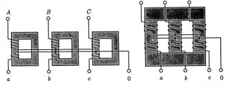
Operating principle of the device
The device is an alternating current transformer that has only a primary winding, with a magnetic gap in the core. The armature being tested is placed in the core gap, and its winding becomes the secondary winding of the transformer. If there are short-circuited turns in the armature being tested, since the turns are distributed in groups, a local magnetic supersaturation of the iron occurs, which is easily detected by the rattling of a steel plate placed on the armature iron above the turn (for example, a hacksaw blade). We rotate the armature in the magnetic gap so that the plate is above the different coils. Where there is an interturn closure, the plate begins to vibrate noticeably. A closed loop theoretically begins to heat up (though, as a rule, on large anchors, too slowly for heating to be practically detectable).
We need two such chokes and a 10-20 uF capacitor at 400 V.
Next, we disassemble the chokes. We beat off the base with a hammer and use it to hit the core along the edge from below. Reminds me of disassembling the universal joint. We get a bunch of such pieces of iron.
We only need these.
We place them as they were in the throttle and insulate them well. In several layers. We pay special attention to the corners of the core. The operation of the device and your safety depend on the quality of the insulation.
Next, we take the removed inductor winding and wind it turn to turn. We insulate each layer of winding with electrical tape. You can also wind it on vertical sections of the core. When the first one ends, solder the second one to it and continue winding. The photo shows the wire for demonstration purposes. It is in PVC insulation. Upon completion of winding, carefully insulate the windings. This is roughly how it should work out.
We connect the capacitor with the winding in series. To limit current. The core can be made long. Taking iron from two chokes.
This is how the anchor should lie.
To find a short circuit, it is convenient to use a hacksaw blade for metal.
Also, using a milliammeter, you can check the winding for open circuits (bad soldering in the cockerels, etc.). To do this, you need to connect the milliammeter to the adjacent lamellas of the armature, turning the armature in the PPY groove by 1 lamella, between connections. In a working armature, the current from all adjacent lamellas will be the same. A sharp increase in current (or drop, if there are several breaks) indicates a break between these lamellas. When checking, it is necessary to maintain a constant angle of contacts of the milliammeter relative to the poles of the device, otherwise the readings on different pairs of lamellas will be different even on a working armature.
And further. If you put the demonstration winding like in the photo, you will get a regular transformer. Anyone interested can download photos and videos. The quality is really not very good.
Source
Self-winding transformer
No transformer? Wind it yourself. The coil is PEDT-200 wire, diameter 0.35. There are approximately 1500 turns plus - the resistance is 40 Ohms, then soak it in varnish and dry everything in the oven, you will have a high-quality and monolithic coil. The price of a device for checking anchors is mere pennies, so try it - everything works great!
If you don’t want to assemble a smooth current regulator on a 2008 microcircuit, make it simpler. Take two coils switched by a switch, a higher current and a smaller one. For testing various rotors.
First put the armature in the cone and apply the plate, when it shakes it means that the rotor is damaged, when it does not shake at any point of the rotor, then you can be sure that there is no short circuit between the coils.
Mechanism of coil formation
The mechanism for the formation of vortices in a transformer is standard for any type of equipment. The total flow during passage is divided into the first flow, which is distributed over planes that are not covered by the pole turns. The second flux of the electromagnet is on a plane that belongs to the square. At the second, an emf is formed, leading to a current pulse. In this case, an angle of a certain value arises, which is determined by the inductance.
Simultaneously with the passage of the flow, an attractive force arises. It consists of two components that are shifted in time. The pulsation (amplitude relationships) is determined purely by the shear angle that occurs between two flows in the area of action. The angle never exceeds 90 degrees. Typically its value lies between 50 and 80 degrees. This is explained by the fact that it is impossible to achieve a shift of flows at a right angle.
Another method for checking the rotor
Another simple way is to check the rotor of such an electric motor by connecting it in series with an incandescent lamp to a 220 V network. Assuming that the armature and brushes are good, we install the rotor in different positions; if it does not start in the given position, then there is a break or short circuit in the rotor - lamp will burn more intensely. You can try different power bulbs depending on the power of the motor. Using this simple method, you can understand that the rotor is working even without dismantling the engine.
Source
Website about DIY inventions
How to detect shorted turns
Detection must be a top priority. These negative phenomena manifest themselves in half the cases during self-assembly of the transformer, mostly during the manufacture of loop coils and chokes. It is imperative to identify and eliminate the defect, since the existing defect will negatively affect the efficiency of the device, lead to a breakdown that is difficult to repair, and pose a risk to the safety of the employee servicing the device.
The determination occurs initially by external signs. If there are visible changes in technical indicators without a reason for this, or a crackling sound is heard, then diagnostics should be carried out. The cause is coil defects. For example, the application of turns in a cross rather than symmetrical manner, the use of low-quality winding from an unverified manufacturer, damage to the insulation during work or when moving the device, mechanical damage. But an effective way to find the turn is not to use electronic devices. Only with their help can one determine the source of damage to the winding and identify its characteristics.
ƒ↓ — Armature testing device (APD)
“By admitting our mistakes, we find the source of strength.”
I decided to make a device for checking anchors for short-circuited turns and so on. It will be useful if you decide to repair the commutator motor and check whether it was wound correctly. A very useful thing and was once produced in the USSR. But now you won’t find it during the day with fire.
We won’t go into complex formulas, I’ll try to explain in a moment what I did. I will split the article into 2 parts. "Part one. Magnetic core." "Part two. Electricity". Then I will explain why there are 2 parts.
Part one. Magnetic core.
Firstly, we need a magnetic circuit, or in other words, a stator from the vacuum cleaner motor. Then we need to cut out a part in one side of it at an angle of 90 degrees, where the anchor itself will lie for testing. You can use a grinder, a saw, a spoon - whatever is more convenient for you.
Next, we need to create a platform for winding the coil. Many people write that you need to take electric cardboard or some other kind, but I don’t have it and it’s not planned in the next 50 kilometers around, there’s nowhere to buy it. This means we need an alternative. Remember, when motorcycle and car engines are being repaired and there is no gasket, it used to be cut out from the “Case No.” folder. That’s what we’ll do, but you need to keep in mind that the folder is rough, a notebook cover will do. I had a similar magnetic circuit and there was electrical cardboard, but a little narrower than needed. But it’s enough for us to measure the thickness and select an approximate one. If only there was a layer between the wire and the stator itself.
Device
To correctly diagnose armature faults, it is important to know the device and the principle of its operation . The main elements of the armature are a round core, consisting of a set of electrical steel plates and a winding wound into its grooves in a certain way. Two armature windings are placed in each of the grooves according to a special pattern . The first and last turns of one of the windings are in the same groove and are closed to one lamella.
Rotor for Makita angle grinder 9069 MAX. Photo 220Volt
The core is pressed onto the rotor , which rotates under the influence of forces arising in the electromagnetic field formed by the armature windings and the stator coils working in tandem with it. In grinders, the anchor is an assembly unit with a drive gear located at one end of the shaft, and a commutator unit at the opposite end.
Short circuit detection methods
Let's consider ways to detect a short circuit in the armature or stator winding. At least four of them are known:
1.1. Contact-by-contact check of winding resistance with an ohmmeter. A sequential resistance measurement is carried out at the collector terminals, which requires a lot of working time. A shorted coil gives a resistance value close to zero.
1.2. The method of alternating electromagnetic field of the inductor. The choke is made (usually homemade) from a large W-shaped or toroidal transformer. The armature being tested is placed in the throttle cone and rotated 360°. When the armature groove, in which there is a short circuit, is combined with a gap in the magnetic circuit of the inductor, a hum or rattle is heard. The dimensions and weight of the device are not for a nerd, look at the samples on YouTube. The stator short circuit cannot be determined with this device.
1.3. The same method, modified for a botanist: the IKZ device (IKZ-2, IKZ-3, etc.), now widely used in the repair of power tools. Rotating the armature, check the windings in the grooves of the magnetic circuit. If there is no short circuit in the slot, the EMF is low and the green LED lights up. If there is a short circuit, a large EMF is induced and the red LED lights up. A very convenient device because, firstly, it is small and light, secondly, it has low consumption, and thirdly, it is possible to check both armatures and stators for short circuits. One drawback: the device does not detect a winding break, that is, if it does not detect a short circuit, this does not mean that the armature/stator is normal. (See description of Table 1).
1.4. Bell counting method. Previous methods involve rotating the armature 360°. It is possible to establish the fact of a short circuit by one measurement in one position of the armature, knowing that the quality factor of normal inductance and defective inductance with a short circuit differ significantly. Figure 1 shows two such cases.
| Picture 1. | At the top is good inductance. Below - short circuit. | |
After exciting the LC circuit with a rectangular pulse, the circuit will “ring” for some time. This ringing can be calculated and a conclusion can be drawn about the quality factor of the circuit, and therefore about the presence or absence of a short circuit.