Magnetic induction is defined as the ability to influence an object using a magnetic field. This ability manifests itself when moving permanent magnet in the coil, as a result of which a current is induced (occurs) in the coil, while the magnetic flux in the coil also increases.
Physical meaning of magnetic induction
Physically, this phenomenon is explained as follows. The metal has a crystalline structure (the coil is made of metal). The crystal lattice of a metal contains electrical charges - electrons. If no magnetic influence is exerted on the metal, then the charges (electrons) are at rest and do not move anywhere.
Dmitry Petrovich VasilievProfessor of Electrical Engineering, St. Petersburg State Polytechnic University If the metal comes under the influence of an alternating magnetic field (due to the movement of a permanent magnet inside the coil - namely movement), then the charges begin to move under the influence of this magnetic field.
As a result, an electric current arises in the metal. The strength of this current depends on the physical properties of the magnet and coil and the speed of movement of one relative to the other.
When a metal coil is placed in a magnetic field, the charged particles of the metal lattice (in the coil) are rotated at a certain angle and placed along the magnetic field lines.
The higher the strength of the magnetic field, the more particles rotate and the more uniform their arrangement will be.
Magnetic fields oriented in one direction do not neutralize each other, but add up, forming a single field.
Application of Lorentz force
This phenomenon is used in sensors used to indirectly measure electric current in locators, cables, and detect the speed of vehicles or turbines. Mass spectrometers, working with this force, calculate the specific charges of elementary particles. The Lorentz effect causes the charges to move in a circle. By measuring the radius of the motion trajectory, you can calculate the specific value, which is the ratio of charge to mass. The expression looks like this:
Q/m=v/(B*r).
Mass spectrometer
Magnetic flux
Magnetic flux is a scalar quantity that characterizes the effect of magnetic induction on a certain metal circuit.
Magnetic induction is determined by the number of lines of force passing through 1 cm2 of the metal section.
The magnetometers used to measure it are called teslometers.
Abrahamyan Evgeniy PavlovichAssociate Professor, Department of Electrical Engineering, St. Petersburg State Polytechnic University The unit of measurement of magnetic induction in the SI system is Tesla (T).
After the movement of electrons in the coil ceases, the core, if it is made of soft iron, loses its magnetic qualities. If it is made of steel, then it has the ability to retain its magnetic properties for some time.
Magnet interaction
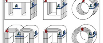
A permanent magnet (or magnetic needle) is oriented along the Earth's magnetic meridian. The end that points north is called the north pole (N), and the opposite end is called the south pole (S). Bringing two magnets closer to each other, we note that their like poles repel, and their opposite poles attract (Fig. 1).
If we separate the poles by cutting a permanent magnet into two parts, we will find that each of them will also have two poles, i.e., it will be a permanent magnet (Fig. 2). Both poles - north and south - are inseparable from each other and have equal rights.
The magnetic field created by the Earth or permanent magnets is represented, like an electric field, by magnetic lines of force. A picture of the magnetic field lines of a magnet can be obtained by placing a sheet of paper over it, on which iron filings are sprinkled in an even layer. When exposed to a magnetic field, the sawdust becomes magnetized - each of them has north and south poles. The opposite poles tend to move closer to each other, but this is prevented by the friction of the sawdust on the paper. If you tap the paper with your finger, the friction will decrease and the filings will be attracted to each other, forming chains depicting magnetic field lines.
In Fig. Figure 3 shows the location of sawdust and small magnetic arrows in the field of a direct magnet, indicating the direction of the magnetic field lines. This direction is taken to be the direction of the north pole of the magnetic needle.
Changes in the Earth's magnetosphere
The characteristics of the earth's MF change mainly due to the fact that it shifts relative to the globe. People are accustomed to the idea that the northern end of the arrow should point north. With reverse magnetization of the planet's dipole, the situation will be the opposite. Observatories record data on the state of the planet’s magnetic field, and geomagnetic maps are created on their basis. They demonstrate the presence of deviations in the magnetic field strength and the position of field lines in some corners of the Earth. These phenomena are called magnetic anomalies. They are sometimes used as indicators of the location of certain fossil resources.
The relationship between induction and field strength is widely used in calculations. It allows you to derive expressions for finding the value of induction in conductors of different shapes, made of materials with different magnetic permeability.
MI vector direction
The direction of magnetic fields can be indicated by a magnet arrow placed in these fields. It will spin until it stops. The northern end of the arrow will show where B→ the unit vector of a particular field is oriented.
Magnetic induction lines
The frame with current behaves in the same way, having the ability to navigate the MP without interference. The direction of the induction vector indicates the orientation of the normal to such a closed electromagnetic circuit.
Attention! The rule of the gimlet (right screw) is used here. If the screw is rotated in the direction of the current in the frame, then the forward movement of the screw will coincide with the direction of the positive normal.
In some cases, the right-hand rule is used to find direction.
Visual display of MI lines
The line to which a tangent can be drawn, coinciding with B→, is called the magnetic induction (MI) line. Using such lines, you can visually display the magnetic field. These are closed contour lines that cover currents. Their density is always proportional to the value of B→ at a specific point in the MP.
Information. When dealing with the magnetic field of direct motion of charged particles, these lines are depicted as concentric circles. They have their center located in a straight line with the current, and are located in planes located at right angles to it.
The direction of magnetic lines can also be determined using the gimlet rule.
Inductance
Electric current passing through a conductor creates a magnetic field around it. The magnetic flux \( \Phi \) through the loop of this conductor is proportional to the induction modulus \( \vec{B} \) of the magnetic field inside the loop, and the magnetic field induction, in turn, is proportional to the current strength in the conductor.
Therefore, the magnetic flux through the loop is directly proportional to the current in the loop:
Inductance is a coefficient of proportionality \( L \) between the current strength \( I \) in the circuit and the magnetic flux \( \Phi \) created by this current:
Inductance depends on the size and shape of the conductor, on the magnetic properties of the environment in which the conductor is located.
The SI unit of inductance is henry (H). The inductance of the circuit is 1 henry if, at a direct current of 1 ampere, the magnetic flux through the circuit is 1 weber:
We can give a second definition of the unit of inductance: an element of an electrical circuit has an inductance of 1 H if, with a uniform change in the current in the circuit by 1 ampere in 1 s, a self-inductive emf of 1 volt occurs in it.
Basic formulas for calculating the MI vector
The magnetic induction vector, the formula of which is B = Fm/I*∆L, can be found using other mathematical calculations.
Law of Electromagnetic Induction
The law of electromagnetic induction (Faraday's law) sounds like this:
The induced emf in a closed loop is equal and opposite in sign to the rate of change of the magnetic flux through the surface bounded by the loop.
Mathematically it can be described by the formula:
| Faraday's law Ɛi — induced emf [V] ΔФ/Δt — rate of change of magnetic flux [Wb/s] |
The “–” sign in the formula allows you to take into account the direction of the induction current. The induced current in a closed circuit is always directed so that the magnetic flux of the field created by this current through the surface bounded by the circuit would reduce those changes in the field that caused the appearance of the induced current.
If the circuit consists of N turns (that is, it is a coil), then the induced emf will be calculated as follows.
| Faraday's law for a circuit of N turns Ɛi — induced emf [V] ΔФ/Δt — rate of change of magnetic flux [Wb/s] N - number of turns [-] |
The strength of the induction current in a closed conductive circuit with resistance R:
| Ohm's law for a conductive circuit Ɛi — induced emf [V] I - induction current strength [A] R - circuit resistance [Ohm] |
If a conductor of length l moves with speed v in a constant uniform magnetic field with induction B the emf of electromagnetic induction is equal to:
| Induction emf for a moving conductor Ɛi — induced emf [V] B—magnetic induction [T] v—conductor speed [m/s] l - conductor length [m] |
The occurrence of induced emf in a conductor moving in a magnetic field is explained by the action of the Lorentz force on free charges in moving conductors. The Lorentz force plays the role of an external force in this case.
A conductor moving in a magnetic field through which an induced current flows experiences magnetic braking. The total work done by the Lorentz force is zero.
The amount of heat in the circuit is released either due to the work of an external force, which maintains the speed of the conductor unchanged, or due to a decrease in the kinetic energy of the conductor.
A change in the magnetic flux penetrating a closed circuit can occur for two reasons:
- due to movement of the circuit or its parts in a time-constant magnetic field. This is the case when conductors, and with them free charge carriers, move in a magnetic field
- due to changes in time of the magnetic field with a stationary circuit. In this case, the occurrence of induced emf can no longer be explained by the action of the Lorentz force. The phenomenon of electromagnetic induction in stationary conductors, which occurs when the surrounding magnetic field changes, is also described by Faraday's formula
Thus, the phenomena of induction in moving and stationary conductors proceed in the same way, but the physical reason for the occurrence of induction current turns out to be different in these two cases:
- in the case of moving conductors, the induced emf is due to the Lorentz force
- in the case of stationary conductors, the induced emf is a consequence of the action on free charges of the vortex electric field that occurs when the magnetic field changes.
Biot-Savart-Laplace Law
Induction EMF formula
Describes the rules for finding B→ magnetic field, which creates a constant electric current. This is an experimentally established pattern. Biot and Savard identified it in practice in 1820, Laplace managed to formulate it. This law is fundamental in magnetostatics. During the practical experiment, a stationary wire with a small cross-section was considered, through which an electric current was passed. For study, a small section of wire was selected, which was characterized by the vector dl. Its module corresponded to the length of the section under consideration, and its direction coincided with the direction of the current.
Interesting. Laplace Pierre Simon proposed to consider even the movement of one electron as a current and, based on this statement, using this law, he proved the possibility of determining the magnetic field of an advancing point charge.
According to this physical rule, each segment dl of a conductor through which electric current I flows forms a magnetic field dB in the space around itself at an interval r and at an angle α:
dB = µ0 *I*dl*sin α /4*π*r2,
Where:
- dB – magnetic induction, T;
- µ0 = 4 π*10-7 – magnetic constant, H/m;
- I – current strength, A;
- dl – conductor section, m;
- r – distance to the point where the magnetic induction is located, m;
- α is the angle formed by r and the vector dl.
Important! According to the Biot-Savart-Laplace law, by summing the magnetic field vectors of individual sectors, it is possible to determine the MF of the desired current. It will be equal to the vector sum.
Biot-Savart-Laplace Law
There are formulas that describe this law for individual cases of MP:
- fields of direct movement of electrons;
- fields of circular motion of charged particles.
The formula for MP of the first type is:
B = µ* µ0*2*I/4*π*r.
For circular motion it looks like this:
B = µ*µ0*I/4*π*r.
In these formulas, µ is the magnetic permeability of the medium (relative).
The law under consideration follows from Maxwell's equations. Maxwell derived two equations for the magnetic field; the case where the electric field is constant is considered by Biot and Savart.
Superposition principle
For MF, there is a principle according to which the total vector of magnetic induction at a certain point is equal to the vector sum of all MI vectors created by different currents at a given point:
B→= B1→+ B2→+ B3→… + Bn→
Lenz's rule
To determine the direction of the induced current, you need to use Lenz's rule.
Academically, this rule is as follows: the induced current excited in a closed loop when the magnetic flux changes is always directed in such a way that the magnetic field it creates prevents the change in the magnetic flux causing the induced current.
Let's try a little simpler: the coil in this case is a dissatisfied granny. They take away her magnetic flux - she is unhappy and creates a magnetic field, which this magnetic flux wants to take back.
They give her a magnetic flux, take it, they say, use it, and she’s like, “Why did I give up your magnetic flux!” and creates a magnetic field, which expels this magnetic flux.
Lenz's rule
The direction of the induction current is determined by Lenz's rule : the induction current excited in a closed loop when the magnetic flux changes is always directed so that the magnetic field it creates prevents the change in the magnetic flux causing the induction current.
Algorithm for solving problems using Lenz's rule:
- determine the direction of the magnetic induction lines of the external magnetic field;
- find out how magnetic flux changes;
- determine the direction of the magnetic induction lines of the magnetic field of the induced current: if the magnetic flux decreases, then they are co-directed with the lines of the external magnetic field; if the magnetic flux increases, it is opposite to the direction of the magnetic induction lines of the external field;
- according to the gimlet rule, knowing the direction of the induction lines of the magnetic field of the induction current, determine the direction of the induction current.
Lenz's rule has a deep physical meaning - it expresses the law of conservation of energy.
Multiples and submultiples of tesla:
Multiples and submultiples are formed using standard SI prefixes.
| Multiples | Dolnye | ||||||
| magnitude | Name | designation | magnitude | Name | designation | ||
| 101 T | decatesla | yesTl | daT | 10−1 T | decitesla | dTl | dT |
| 102 T | hectotesla | gTl | hT | 10−2 T | centitesla | stl | cT |
| 103 T | kilotesla | kT | kT | 10−3 T | millitesla | mTl | mT |
| 106 T | megatesla | MTL | M.T. | 10−6 T | microtesla | µT | µT |
| 109 T | gigatesla | GTL | GT | 10−9 T | nanotesla | nTl | nT |
| 1012 T | teratesla | TTL | TT | 10−12 T | picotesla | pTl | pT |
| 1015 T | petatesla | PTl | P.T. | 10−15 T | femtotesla | ftl | fT |
| 1018 T | exatesla | ETL | ET | 10−18 T | attotesla | atl | aT |
| 1021 T | zettatesla | ZTL | ZT | 10−21 T | zeptotesla | ztl | zT |
| 1024 T | iottatesla | ITl | YT | 10−24 T | ioctotesla | iTl | yT |