Any transformer, with the exception of an autotransformer, has at least two windings: high and low voltage. Also, for three-phase devices, each of the windings consists of three parts (according to the number of phases). The large number of parts allows for multiple inclusion options. To avoid confusion, all transformer winding connection groups for three-phase devices are standardized and brought into a single system for error-free connection of devices and the possibility of parallel operation.
The concept of a group connecting the windings of a three-phase transformer
Three-phase networks use two types of connections: star and delta. When making structures, it may seem that there are only four types of winding arrangements:
- Star-star.
- Star-triangle.
- Triangle-star.
- Triangle-triangle.
In reality, everything is more complicated, since in each type of connection (star or triangle) the parts of the windings can be connected differently. An example is a conventional two-winding transformer. If such a device has the same beginnings and ends of the windings, then the phase shift will be equal to 0. Turning one of the windings will give a phase shift of 1800.
There are also z-shaped winding connections (zigzag). In such designs, each of the windings consists of two parts located on different cores of the transformer magnetic circuit.
A three-phase network is characterized by a phase shift relative to one another by 1200. Therefore, there are a total of 12 connection groups. Each group is characterized by a certain shift of the same phases at the input and output of the transformer.
Types of magnetic cores of power transformers.
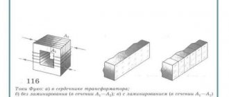
The magnetic core of the low-frequency transformer consists of steel plates. Using laminations instead of a solid core reduces eddy currents, which increases efficiency and reduces heat.
Magnetic cores of type 1, 2 or 3 are produced by stamping.
Magnetic cores of types 4, 5 or 6 are produced by winding a steel tape onto a template, and magnetic cores of types 4 and 5 are then cut in half.
Magnetic cores are:
1, 4 – armored,
2, 5 – rod,
3, 6 – ring.
True, I have never seen stamped ring magnetic cores.
To determine the cross-section of the magnetic circuit, you need to multiply the dimensions “A” and “B”. For calculations in this article, the section size in centimeters is used.
Transformers with twisted rod position 1 and armored magnetic cores position 2.
Transformers with stamped armored magnetic cores, position 1, and core magnetic cores, position 2.
Transformers with twisted ring magnetic cores.
More information about magnetic cores in the chapter - “Disassembly and assembly of transformers”.
Return to top menu
Symbols and explanation
Groups are marked with numbers from 0 to 11. For convenience and standardization, the following is accepted:
- connections of the same type (∆/∆, Y/Y) have even numbers;
- heterogeneous connections (∆/Y, Y/∆) – odd.
Three-phase transformers are made on core magnetic cores. Each phase is located on a separate rod. This greatly simplifies further work and coordination of devices with each other.
If a transformer has identical phases wound on the same rods, then the groups of connections are called main (0, 6, 11, 5). The remaining groups are derivatives.
Since the minimum phase shift can be 300, the number of options is 12, which corresponds to the positions of the clock hands. The 0th and 12th positions are the same. Based on this, they say that the group number coincides with the position of the hour and minute hands. The phase shift is calculated simply:
Group number*300.
The following designations are accepted on electrical circuits and devices:
- Y, U – star;
- Yn, Un – star on the low voltage side;
- Yo, Uo – star with zero point;
- ∆, D, D – triangle;
- ∆н, Дн, Dн – triangle on the low voltage side.
An example of marking a two-winding transformer:
- ∆/Yн – 11. Primary winding triangle, secondary (step-down) star. Phase shift 3300;
- Y/Yо -0. Both windings are connected in a star, the secondary with the zero point removed. There is no phase shift.
Also on electrical diagrams, high voltage (HV) windings are designated by the following symbols:
- A, B, C – beginning of the winding;
- X, Y, Z – end of the winding.
Likewise for the low voltage side:
- a, b, c;
- x, y, z.
Multi-winding devices are marked in a similar way, for example:
Yo/Y/∆ – 0 – 11.
Instead of the zero group, the twelfth group can be indicated, which is completely equivalent.
Transformers on diagrams
The transformer is designated on the schematic diagrams as follows:
Transformer designation on diagrams
The following figure shows a transformer with multiple secondary windings:
Transformer with two secondary windings
The number “1” indicates the primary winding (on the left), numbers 2 and 3 indicate the secondary windings (on the right).
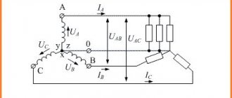
How vector diagrams are constructed
When constructing vector diagrams, you need to remember the rule that the phase shift between the phases is 1200, that is, if the voltages are equal, the ends of the vectors will always form an equilateral triangle.
The simplest diagram to draw is for a star connection. A point is placed in the center of the diagram, which corresponds to the combined ends of the windings. Phase vectors are drawn from the center at angles of 1200. The vector of the middle phase is drawn vertically.
For a triangle, draw a line parallel to the corresponding phase of the star, and from its ends, respectively, the remaining two phases are connected to it. The condition must be met - all sides of the triangle must be parallel to the corresponding phases of the star. The required vectors will be lines drawn from the center of the triangle to its vertices.
Vector diagrams are drawn for the high and low sides and then aligned with a single center. The angle between like phases will indicate the connection group number expressed in hours.
The count must be taken from the high voltage vector to the low one.
Transformers - purpose, types and characteristics
To bookmarks
Introduction
A transformer is a static device having two or more windings, designed to convert, by electromagnetic induction, one or more alternating voltage and current systems into one or more other alternating voltage and current systems, usually having different values at the same frequency, for the purpose of transmitting power . (Source: GOST 30830-2002)
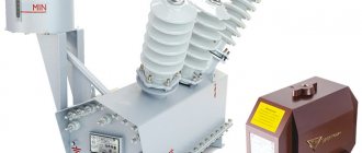
Fig.1 General view of the transformer
The importance of transformers both in the electric power industry in general and in the everyday life of every person can hardly be overestimated; they are used everywhere: at substations, in cities and towns, there are power transformers that lower high voltages of thousands and even tens of thousands of volts to the usual 380/220. Volt, enterprises have welding transformers that are absolutely indispensable in production; transformers are also used at home in household appliances: in microwave ovens, computer power supplies and even phone chargers.
In this article we will understand how transformers are structured and how they work, what types of transformers there are, and also give their general characteristics.
General structure and principle of operation of transformers
In general, a transformer consists of two windings located on a common magnetic circuit. The windings are made of copper or aluminum wire in enamel insulation, and the magnetic core is made of thin varnish-insulated electrical steel plates to reduce electricity losses due to eddy currents (the so-called Foucault currents).
The winding that is connected to the power source is called the primary winding, and the winding to which the load is connected is called the secondary winding. If a voltage (U2) is removed from the secondary winding (W2) of a transformer lower than the voltage (U1) supplied to the primary winding (W1), then such a transformer is considered a step-down transformer, and if higher, it is considered a step-up transformer.
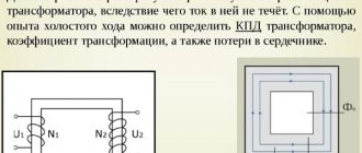
Fig. 2 Diagram of the general structure of the transformer
The metal part on which the electrical winding (coil) is located, i.e. which is located in its center is called a core, in transformers this core has a closed design and is common to all windings of the transformer, such a core is called a magnetic circuit.
As mentioned above, the operating principle of transformers is based on the law of electromagnetic induction; to understand how this works, let’s imagine the simplest transformer, similar to the one shown in Figure 2, i.e. we have a magnetic circuit on which there are 2 windings, imagine that the first winding consists of only one turn, and the second - of two.
Now let’s apply a voltage of 1 Volt to the first winding, its only turn will conditionally create a magnetic flux of 1 Wb (For reference: Weber (Wb) is a unit of measurement of magnetic flux) in the magnetic core, since the magnetic core has a closed design; the magnetic flux will flow in it in a circle while crossing 2 turns of the second winding, in each of these turns, due to electromagnetic induction, it induces (induces) an electromotive force (EMF) of 1 Volt, the EMF of these two turns adds up and at the output from the second winding we get 2 Volts.
Thus, by applying 1 Volt to the primary winding, we received 2 Volts on the secondary winding, i.e. in this case, the transformer will be called a step-up transformer, because it increases the voltage applied to it.
But this transformer can also work in the opposite direction, i.e. if 2 Volts are applied to the second winding (with two turns), then from the first winding according to the same principle we will receive 1 Volt, in this case the transformer will be called a step-down transformer.
General characteristics of transformers
The main technical characteristics of transformers include:
- rated power;
- rated voltage of windings;
- rated current of windings;
- transformation ratio;
- efficiency;
- number of windings;
- operating frequency;
- number of phases.
Power is one of the main parameters of transformers. The passport (factory) data of the transformer indicates its total power (indicated by the letter S), it depends on the type of magnetic circuit used, the number and diameter of turns in the windings, that is, on the weight and dimensions of the electromagnetic device.
Power is measured in units of VA (Volt-Ampere). In practice, for high-power transformers, as a rule, multiples of Volt-Amps are used: Kilovolt-ampere - kVA (103 VA∙A) and Megavolt-ampere - MVA (106 VA∙A).
In fact, each transformer has 2 power values: input (S1) - the power that the transformer consumes from the network supplying it and output (S2) - the power that the transformer gives to the load connected to it, while the output power is always less than the input due to electrical losses in in the transformer itself (winding heating losses, eddy current losses, etc.), the magnitude of these losses is determined by another main parameter - the coefficient of performance, abbreviated as efficiency (denoted by the letter η), this parameter is indicated as a percentage.
For example, if the efficiency is specified as 92%, this means that the output power of the transformer will be 8% less than the input power, i.e. 8% is the loss in the transformer.
Power calculation formulas:
- Input power: S1=U1x I1 ,VA;
- Output power: S2=U2x I2 ,VA;
Where:
- I1, I2 - respectively, currents in the primary and secondary windings of the transformer in Amperes;
- U1, U2 - respectively, the voltages of the primary and secondary windings of the transformer in Volts.
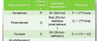
It should be remembered that total power consists of active (P) and reactive (Q) powers:
- Active power is determined by the formula: P=U x I x cosφ , Watt (W)
- Reactive power is determined by the formula: Q=U x I x sinφ , volt-ampere reactive (Var)
- Power factor: cosφ=P/S;
- Reactive power factor: sinφ =Q/S
Formulas for calculating the efficiency (η) of a transformer:
As already mentioned above, the efficiency determines the amount of losses in the transformer or, in other words, the operating efficiency of the transformer and is determined by the ratio of the output power ( P2 ) to the input power ( P1 ):
η=P2/P1
As a result of this calculation, the efficiency value is determined in relative units (in the form of a decimal fraction), for example - 0.92, in order to obtain the efficiency value as a percentage, the calculated value must be multiplied by 100% (0.92*100%=92%).
The closer the efficiency is to 100%, the better, i.e. an ideal transformer is a transformer in which P2=P1 , but in reality, due to losses in the transformer, the output power is always lower than the input power.
This can be clearly seen from the so-called energy diagram of the transformer (Fig. 3):
- P1 is the active power consumed by the transformer from the source;
- P2 - active (useful) power supplied by the transformer to the receiver;
- ∆Pel - electrical losses in the transformer windings;
- ∆Рм — magnetic losses in the magnetic core of the transformer;
- ∆Рdop - additional losses in other structural elements.
In the no-load mode (operation without a load connected to the transformer), the efficiency of the transformer is η = 0. The no-load power P0 consumed by the transformer in this mode is spent on compensating for magnetic losses. With increasing load in a fairly small range (approximately β = 0.2), the efficiency reaches large values. In the rest of the operating range, the efficiency of the transformer remains at a high level. In modes close to the nominal one, the efficiency of the transformer is η nom = 0.9 - 0.98.
The dependence of efficiency on load is presented in the following graph (Fig. 4):
The primary rated voltage U1n is the voltage that must be applied to the primary coil of the transformer in order to obtain the rated secondary voltage U2n in no-load mode.
The secondary rated voltage U2н is the value that is set at the terminals of the secondary winding when the rated primary voltage U1н is applied to the primary winding in no-load mode.
Rated primary current I1н is the maximum current flowing in the primary winding, i.e. consumed by the transformer from the network for which this transformer is designed and at which its long-term operation is possible.
The rated secondary current I2n is the maximum load current flowing in the secondary winding for which this transformer is designed and at which its long-term operation is possible.
Transformation ratio ( kt) is the ratio of the number of turns in the primary winding to the number of turns in the secondary winding k=W1/W2.
Also kt is defined as the ratio of voltages at the winding terminals: kt = U1n/U2n.
For a step-down transformer, the transformation ratio is greater than 1, and for a step-up transformer, it is less than 1.
Note: for current transformers kt is defined as the ratio of the rated values of the primary and secondary currents kt = I1n/I2n
The number of windings for single-phase transformers is usually two, but can be more. One voltage value is applied to the primary winding, and another value is removed from the secondary winding.
When different voltages are required to power several devices, then in this case there may be several secondary windings. There are also transformers with a common point on the secondary winding for bipolar power supply.
The operating frequency of transformers may vary. But with the same primary winding voltages, a transformer designed for a frequency of 50 Hz can be used at a mains frequency of 60 Hz, but not vice versa. At a frequency lower than the nominal one, the induction in the magnetic circuit increases, which can lead to its saturation and, as a consequence, a sharp increase in the no-load current and a change in its shape. At a frequency higher than the rated one , the magnitude of parasitic currents in the magnetic core increases, the heating of the magnetic core and windings increases, leading to accelerated aging and destruction of the insulation.
The dimensions of the transformer directly depend on the frequency of the current in the circuit in which it will be installed. Of course, the transformer must be designed for this frequency. This dependence is inverse, i.e. As the frequency increases, the dimensions of the transformer decrease significantly. That is why switching power supplies (with pulsed high-frequency transformers) are much more compact.
Depending on the purpose, transformers are made single-phase and three-phase.
A single-phase transformer is a device for transforming electrical energy in a single-phase circuit. Basically it has two windings, primary and secondary, but there can be several secondary windings.
A three-phase transformer is a device for transforming electrical energy in a three-phase circuit. Structurally, it consists of three magnetic cores connected by an upper and lower yoke. Each rod is equipped with windings W1 and W2 of the highest (U1) and low (U2) voltages of each phase (Fig. 5).
Types of transformers
All transformers can be divided into the following types:
- power;
- autotransformers;
- measuring;
- dividing;
- coordinating;
- pulse;
- peak transformers;
- welding
Power transformers are the most common type of industrial transformer. They are used to increase or decrease voltage. They are an integral part of the power supply network for enterprises, settlements, etc.
An autotransformer is a transformer that has only one winding with the number of turns W1. Part of this winding with the number of turns W2 belongs simultaneously to the primary and secondary circuits:
This type of transformers is used in automatic voltage regulation devices. These devices are used, for example, in educational institutions for carrying out laboratory work; they can be found in electrical laboratories of various enterprises for carrying out test work.
Appearance of autotransformers:
Instrument transformers are divided into voltage transformers and current transformers. They provide galvanic isolation between high and low voltage circuits. As the name suggests, the main application is to reduce the primary voltage or current to a value used in measuring circuits, for example for connecting ammeters, voltmeters, and electricity meters. They can also be used in various protection, control and signaling circuits. They differ from other types of transformers by increased accuracy and stability of the transformation ratio.
Example of instrument transformers:
→ Read more about instrument transformers here.
Isolation transformers , these devices are not much different from conventional step-down or step-up transformers. The only difference is that absolutely identical windings are placed on a common magnetic core. That is, they completely match such parameters as wire cross-section, number of turns, insulation. Therefore, their transformation coefficient is equal to one.
The task of these devices is to provide galvanic isolation, i.e. exclusion of direct electrical connection between the electrical network and the equipment connected to it through this transformer.
They are used in areas where there are increased requirements for electrical safety, such as connecting medical equipment.
Matching transformers are used to match the resistance of various parts of cascades of electronic circuits, as well as to connect a load that does not correspond in resistance to the permissible values of the signal source, which makes it possible to transfer maximum power to such a load. In this case, the direct change in current and voltage indicators does not matter.
They are used in low-frequency amplifiers as input, interstage and output transformers.
As input, matching transformers are used in sound-reproducing equipment to connect microphones and sound pickups of various types.
Transformers of this type are used to match the signal when connecting antennas to receiving and transmitting devices.
Pulse transformers are devices with a ferromagnetic core that are used to change pulses of current or voltage. Convert the received signal into a rectangular pulse. Used to prevent high frequency interference. Pulse transformers are most often used in electronic computing devices, radar systems, pulse radio communications, and as measuring devices in electricity meters
Peak transformers - convert sinusoidal voltage into pulse peaks while maintaining their polarity and oscillation frequency.
Indispensable where starting the actuator requires a single pulse with a set voltage amplitude. These are, for example, control electronic circuits assembled using thyristors. They are also used as pulse generators, mainly in high-voltage research facilities, communications and radar technology. Peak transformers are most widely used in process automation.
Welding transformers are the main power sources for manual arc welding on alternating current. They serve to reduce the network voltage from 220V or 380V to a safe one and at the same time increase the current value to increase the temperature of the electric arc.
→ Read more about welding transformers here.
Was this article useful to you? Or maybe you still have questions ? Write in the comments!
Didn’t find an article on the website on a topic that interests you regarding electrical engineering? Write to us here. We will definitely answer you.
↑ Up
0
https://elektroshkola.ru/transformatory/transformatory-naznachenie-vidy-i-xarakteristiki/
Connection group table
The table below shows the designations of the connection groups and the phase rotation of the low and high sides.
| Connection group | Designation | Phase rotation |
| 0 | Y/Y-0 | C, B, A |
| c, b, a | ||
| ∆/∆-0 | C, B, A | |
| c, b, a | ||
| 1 | Y/∆-1 | C, B, A |
| c, b, a | ||
| ∆/Y-1 | C, B, A | |
| c, b, a | ||
| 2 | Y/Y-2 | C, B, A |
| c, b, a | ||
| ∆/∆-2 | C, B, A | |
| a, c, b | ||
| 3 | Y/∆-3 | C, B, A |
| b, a, c | ||
| ∆/Y-3 | C, B, A | |
| b, a, c | ||
| 4 | Y/Y-4 | C, B, A |
| b, a, c | ||
| ∆/∆-4 | C, B, A | |
| b, a, c | ||
| 5 | Y/∆-5 | C, B, A |
| c, b, a | ||
| ∆/Y-5 | C, B, A | |
| c, b, a | ||
| 6 | Y/Y-6 | C, B, A |
| c, b, a | ||
| ∆/∆-6 | C, B, A | |
| c, b, a | ||
| 7 | Y/∆-7 | C, B, A |
| c, b, a | ||
| ∆/Y-7 | C, B, A | |
| c, b, a | ||
| 8 | Y/Y-8 | C, B, A |
| a, c, b | ||
| ∆/∆-8 | C, B, A | |
| c, b, a | ||
| 9 | Y/∆-9 | C, B, A |
| b, a, c | ||
| ∆/Y-9 | C, B, A | |
| b, a, c | ||
| 10 | Y/Y-10 | C, B, A |
| c, b, a | ||
| ∆/∆-10 | C, B, A | |
| b, a, c | ||
| 11 | Y/∆-11 | C, B, A |
| c, b, a | ||
| ∆/Y-11 | C, B, A | |
| c, b, a |
Determination by galvanometer method
There are several ways to determine whether the windings are connected correctly. The easiest way is to use a magnetoelectric system voltmeter. It is also called the direct current method.
To do this, a measuring device is connected to the ends of the winding being tested, and a constant voltage is applied to the other winding. The deflection of the arrow at the moment the key is closed will indicate the polarity of the winding connection. Such actions are performed for each winding.
You can also use a simple voltmeter when connecting AC voltage. To do this, a reduced alternating voltage is supplied to one of the windings, and the remaining two windings are connected in series and connected to a voltmeter. Absence or too small readings indicate that the windings are connected in opposite directions.
Examination
If the transformation ratio is known, then using a voltmeter you can determine the number of the main connection group. For this purpose, voltage is applied to ends A and a or x and y and the voltages are measured at terminals B-c and C-c when connected in a star, or By and Cz when connected in a triangle. The following ratios are used for verification:
UBb = UCc = UAa(k-1) Group Y/Y-0
UBy = UCz = Uxy(k+1) Y/Y-6
UBb = UCc = UAa(√(1-√3k+k2)) Y/∆-11
UBy = UCz = Uxy(√(1+√3k+k2)) Y/∆-5
To avoid equipment damage, emergency situations and injury, all measurements should be made at low voltage, without connecting the equipment to the main network of the enterprise.
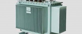
Welding transformers
There are special welding transformers.
Welding transformer
The welding transformer is designed for electric arc welding; it works as a step-down transformer, reducing the voltage on the secondary winding to the required value for welding. The voltage of the secondary winding is no more than 80 Volts. Welding transformers are designed for short-term short circuits of the output of the secondary winding, in which an electric arc is formed, and the transformer does not fail, unlike a power transformer.
Examples of group winding connections
The state standard provides only two groups of winding connections:
- Y/Y-0 or ∆/∆-0
- Y/∆-11 and ∆/Y-11
Strict standardization eliminates accidents and damage resulting from incorrect connections. In addition, for transformers of the same power and transformation ratio, parallel connection of devices becomes possible.
The remaining number of connections is used extremely rarely in some cases when it is impossible to use the standard option.
The type of connection must be specified in the accompanying documentation and duplicated on the device nameplate.
What is transformation ratio?
One of the main parameters of a transformer is its transformation ratio. Let's consider what its meaning is. To do this, we accept the assumption that the magnetic stray field is reduced to a minimum and is practically equal to zero. Then the primary and secondary windings are penetrated by the same magnetic flux PV . And in accordance with the law of electromagnetic induction, the electromotive force at the terminals of the transformer windings is determined by the following expressions
where E1 and E2 are the emf at the terminals of the primary and secondary windings, respectively,
ω1 and ω2 – number of turns of the primary and secondary windings, respectively,
dFV/dt – rate of change of magnetic flux.
Then, equating the last part of both expressions, we obtain the relation that determines the value of the transformation coefficient
where n is the transformation coefficient.
Thus, the transformation ratio n is the ratio of the number of turns of the primary ω 1 to the number of turns of the secondary ω 2 winding.
Depending on the value of the transformation ratio, the transformer can be step-down when n > 1, and step-up when n < 1. In a step-up transformer, the EMF of the secondary winding is greater than in the primary E1 < E2, and in a step-down transformer – E1 > E2.
Erroneous designations
Erroneous connections occur when the rules for connecting the ends are not followed. This occurs as a result of incorrect winding or incorrect designation. As a result, when the device is connected to a three-phase network, the windings connected in opposite directions compensate each other’s magnetic fluxes, so a current begins to flow through them, limited only by the active resistance of the winding wire, which is equivalent to a short circuit.
To eliminate cases of incorrect switching, it is recommended that after repairing equipment or before switching on unknown devices, carefully check the phasing of each winding using several methods to eliminate possible errors.
A preliminary calculation of voltages for measurements using the voltmeter method will help reduce the likelihood of error. The data obtained serve as guide values that need to be taken into account when making subsequent measurements.