Description of the operating principle and device
The main difference between these elements and thyristors is the bidirectional conductivity of electric current. Essentially, these are two SCRs with common control, connected back-to-back (see A in Fig. 1).
Rice. 1. Circuit with two thyristors, as an equivalent of a triac, and its conventional graphic designation
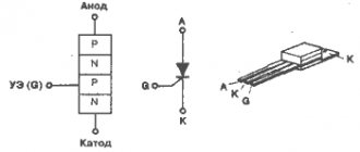
This gave the name to the semiconductor device, as a derivative of the phrase “symmetrical thyristors” and was reflected in its UGO. Let us pay attention to the designations of the terminals, since current can be carried in both directions, the designation of the power terminals as Anode and Cathode does not make sense, therefore they are usually designated as “T1” and “T2” (options TE1 and TE2 or A1 and A2 are possible). The control electrode is usually designated “G” (from the English gate).
Now consider the structure of the semiconductor (see Fig. 2.) As can be seen from the diagram, there are five junctions in the device, which allows you to organize two structures: p1-n2-p2-n3 and p2-n2-p1-n1, which, in fact, are two counter-current thyristors connected in parallel.
Rice. 2. Block diagram of a triac
When negative polarity is formed at the power terminal T1, the trinistor effect begins to manifest itself in p2-n2-p1-n1, and when it changes, p1-n2-p2-n3.
Concluding the section on the principle of operation, we present the current-voltage characteristics and the main characteristics of the device.
I-V characteristics of the triac
Designation:
- A – closed state.
- B – open state.
- UDRM (UPR) – maximum permissible voltage level for direct connection.
- URRM (UOB) – maximum reverse voltage level.
- IDRM (IPR) – permissible direct current level
- IRRM (IOB) - permissible level of reverse switching current.
- IN (IUD) – holding current values.
General information
A triac (triac) is a type of thyristor and has a large number of pn-type transitions. It is advisable to use it in AC circuits for electronic control. To understand the principle of operation of a triac for dummies in this matter, one should consider its structure, function and scope of application.
Key information
Keys are devices that are used for switching or switching in electrical circuits. There are three types, and each of them has its own advantages and disadvantages. Keys are classified according to switching type:
- Mechanical.
- Electromechanical.
- Electronic.
Mechanical keys include switches and switches. They are used in cases where manual switching is necessary to close one or more groups of contacts. The type of electromechanical keys includes relays (contactors). An electromagnetic relay consists of a magnet, which is a coil with a movable core. When power is applied to the coil, it attracts a core with a group of contacts: some contacts close, while others open.
Among the advantages of using electromechanical switches are the following: the absence of voltage drop and power loss on the contacts, as well as the isolation of load and switching circuits. This type of keys also has disadvantages:
- The number of switching operations is limited because the contacts wear out.
- When opened, an electric arc occurs, which leads to the destruction of contacts (electrical erosion). Cannot be used in explosive environments.
- Very slow performance.
Electronic switches come in different bases of semiconductor elements: transistors, controlled diodes (thyristors) and symmetrical controlled diodes (triacs). The simplest electronic switch is a bipolar transistor with a collector, emitter and base, consisting of 2 pn junctions. According to their structure, they are of 2 types: npn and p-np.
Since the transistor consists of 2 pn junctions, depending on the state in which they are located, there are 4 operating modes: main, inverse, saturation and cutoff. In the active mode, the collector junction is open, and in the inverse mode, the emitter junction is open. With two open junctions, the transistor operates in saturation mode. Provided that both transitions are closed, it will operate in cutoff mode.
To use a transistor, only 2 of its states are needed. The cutoff mode occurs in the absence of base current, therefore, the collector current is equal to 0. When a sufficient current value is supplied to the base, the semiconductor device will operate in saturation mode, i.e., in the open state.
If we consider switches on field-effect transistors, then it becomes possible to change its conductivity when the voltage on the gate, which serves as the control electrode, changes. By controlling its operation by influencing the shutter, two states can be obtained: open and closed. Switches based on field-effect transistors are faster than switches based on bipolar transistors.
You might be interested in the principle of operation and design of a magnetically controlled reed switch
Electronic keys made on thyristors have some special features. A thyristor is a semiconductor radio element with pnpn or npnp junctions and has 3 and sometimes 4 outputs. It consists of a p-layer (cathode), an n-layer (anode) and a control electrode (base). It can be replaced with 2 transistors of different structures. It represents 2 transistor type switches that are connected back to back. The base of one transistor is connected to the collector of the other.
When a gate current is applied to the base, the controlled diode will open and remain in this state until the current value is reduced to zero. When the base current is large, the thyristor is an ordinary semiconductor diode that conducts current in one direction.
It can operate on AC circuits, but only at half power. For these purposes, it is necessary to use a triac.
The principle of operation of a triac
The main difference between a triac and a thyristor is conductivity in two directions at once. The triac can be replaced by 2 thyristors, which have a back-to-back connection in Figure 1. It shows the conventional graphic designation of a triac on electrical circuit diagrams. In some literature you can find other names : triac and symmetrical controlled diode.
Figure 1. Triac (circuit for connecting 2 thyristors) and its graphic designation
There is a simple example that will allow even “dummies” to understand how a triac works. The door in the hotel can be opened in two directions, and 2 people can enter and exit it at once. This simple example shows that a triac can carry current in two directions (forward and reverse) at once, since it consists of 5 pn junctions. Its operation is controlled using the database.
The triac switch layers, made of semiconductor, are similar to the transistor junction, but have 3 additional n-type regions. The fourth layer is located near the cathode and is separated, since the anode and cathode perform certain functions when the current flows, and change places when the current flows in the opposite direction. The fifth layer is located near the base.
When a signal is applied to the control pin, the symmetrical controlled diode will be unlocked, since its anode will have a positive potential. In this case, current will flow through the upper thyristor. When the polarity changes, current will flow through the lower thyristor (Figure 1). This is evidenced by its current-voltage characteristic (volt-ampere characteristic) in Figure 2. It consists of two curves rotated by 180 degrees.
Figure 2. I-V characteristics of the triac
The letter “A” indicates its closed state, and “B” indicates its open state. Urrm and Udrm are permissible values of forward and reverse voltages. Idrm and Irrm - forward and reverse currents.
Types and scope of application
Since a triac is a type of thyristor, their main difference is the parameters of the control electrode (base). In addition, they are classified according to other criteria:
- Design.
- The current value at which an overload occurs.
- Base characteristics.
- Values of forward and reverse currents.
- The magnitude of forward and reverse voltages.
- Type of electrical load. There are power and normal ones.
- Parameter of the current required to open the gate.
- The dv/dt ratio or the speed at which switching occurs.
- Manufacturer.
- Power.
You might be interested in AC Ammeter Device
Due to the feature of passing current in two directions, they are used in alternating current circuits, since the thyristor cannot operate at full power. Symmetrical thyristors are widely used in the following devices:
- Devices for adjusting the brightness of light or dimmers.
- Speed controllers for various tools (jigsaws, screwdrivers, etc.).
- Electronic temperature control for induction cookers.
- Refrigeration equipment for smooth engine starting.
- Household appliances.
- Industry for lighting, smooth starting of machine drives and mechanisms.
Among the advantages of triacs are their low cost, reliability and they do not generate interference (mechanical type contacts are not used), as well as a long service life. The main disadvantages include the following: the need for additional heat removal, the inability to use at high frequencies, as well as the influence of interference and noise of various kinds.
To suppress interference, you should connect in parallel to the triac, between the cathode and anode, a chain of a capacitor and a resistor with ratings from 0.02 to 0.3 μF and from 45 to 500 Ohms, respectively. For use in any circuit or device, you should know the basic technical characteristics, since knowledge of this information will help avoid many difficulties for a novice radio amateur.
Peculiarities
To have a complete understanding of symmetrical thyristors, it is necessary to talk about their strengths and weaknesses. The first include the following factors:
- relatively low cost of devices;
- long service life;
- lack of mechanics (that is, moving contacts that are sources of interference).
The disadvantages of the devices include the following features:
- The need for heat removal is approximately at the rate of 1-1.5 W per 1 A, for example, at a current of 15 A, the power dissipation value will be about 10-22 W, which will require an appropriate radiator. For ease of fastening to it for powerful devices, one of the terminals has a thread for a nut.
Triac with radiator mount
- Devices are subject to transients, noise and interference;
- High switching frequencies are not supported.
The last two points require a little clarification. In the case of high switching speed, there is a high probability of spontaneous activation of the device. Interference in the form of a voltage surge can also lead to this result. To protect against interference, it is recommended to bypass the device with an RC circuit.
RC circuit to protect the triac from interference
In addition, it is recommended to minimize the length of the wires leading to the controlled output, or alternatively use shielded conductors. It is also practiced to install a shunt resistor between the T1 terminal (TE1 or A1) and the control electrode.
Specifications
Triacs have characteristics that allow them to be used in any circuit. In addition, they also differ in manufacturer - there are domestic and imported. The main difference between imported ones is that there is no need to adjust their operation using additional radio elements, that is, to assemble an additional triac control circuit. Triacs have the following characteristics:
- The value of the maximum reverse and pulse voltage values for which it is designed.
- The minimum and maximum current values at which its transition opens, as well as the value of the maximum pulse current required to open it.
- On and off period.
- dv/dt ratio.
Characteristics are mainly determined by triac labeling using a reference book. The reference information contains information about what it looks like and gives its pinout. When using a triac, the dv/dt characteristic should be taken into account. It shows the coefficient values at which spontaneous switching does not occur due to voltage surges. The reasons for this inclusion may be interference of pulse origin and a voltage drop when switching the switch. In addition, to avoid consequences, an RC circuit should be used, as well as limiting diodes or a varistor. This chain is connected to the emitter and collector of the triac.
You might be interested in Do-it-yourself generator from an asynchronous motor
When choosing a triac, you should pay attention to all the characteristics, since it does not make sense to use a high-voltage type in low-voltage circuits. For example, if the device operates on a voltage of 36 V, then the foreign triac Zo607 with a voltage of 600 V (its analogue is VTA41600V) should not be used.
In addition, in some sources you can find the concept of a snubberless triac. This is the type that is used for inductive loads. Examples of such a model are m10lz47, mac12n and tg35c60.
Application
This type of semiconductor elements was originally intended for use in the manufacturing sector, for example, to control electric motors of machine tools or other devices where continuously variable current control is required. Subsequently, when the technical base made it possible to significantly reduce the size of semiconductors, the scope of application of symmetrical thyristors expanded significantly. Today, these devices are used not only in industrial equipment, but also in many household appliances, for example:
- chargers for car batteries;
- household compressor equipment;
- various types of electric heating devices, ranging from electric ovens to microwaves;
- hand-held electric tools (screwdriver, hammer drill, etc.).
And this is not a complete list.
At one time, simple electronic devices were popular that allowed smooth adjustment of lighting levels. Unfortunately, dimmers based on symmetrical thyristors cannot control energy-saving and LED lamps, so these devices are not relevant now.
What is a triac and what is it for?
In power electronics, one type of thyristor, thyristor, is often used as a controlled switching element. Their advantages:
- lack of contact group;
- absence of rotating and moving mechanical elements;
- small weight and dimensions;
- long service life, independent of the number of on-off cycles;
- low cost;
- high performance and silent operation.
But when using thyristors in alternating current circuits, their one-way conductivity becomes a problem. In order for the SCR to pass current in two directions, you have to resort to tricks in the form of parallel connection in the opposite direction of two SCRs controlled simultaneously. It seems logical to combine these two SCRs in one shell for ease of installation and reduction in size. And this step was taken in 1963, when Soviet scientists and General Electric specialists almost simultaneously filed applications to register the invention of a symmetrical trinistor - triac (in foreign terminology, triac - triode for alternative current).
How to check the functionality of a triac?
You can find several methods online that describe the testing process using a multimeter; those who described them, apparently, have not tried any of the options themselves. In order not to be misleading, you should immediately note that testing with a multimeter will not be possible, since there is not enough current to open the symmetrical SCR. Therefore, we are left with two options:
- Use a pointer ohmmeter or tester (their current strength will be sufficient to trigger).
- Collect a special circuit.
Algorithm for checking with an ohmmeter:
- We connect the probes of the device to terminals T1 and T2 (A1 and A2).
- Set the multiplicity on the ohmmeter x1.
- We carry out a measurement, a positive result will be infinite resistance, otherwise the part is “broken” and can be gotten rid of.
- We continue testing, to do this we briefly connect pins T2 and G (control). The resistance should drop to about 20-80 ohms.
- Change the polarity and repeat the test from steps 3 to 4.
If during the test the result is the same as described in the algorithm, then with a high probability it can be stated that the device is operational.
Note that the part being tested does not have to be dismantled; it is enough to just turn off the control output (naturally, having first de-energized the equipment where the part that raises doubt is installed).
It should be noted that this method does not always allow reliable testing, with the exception of testing for “breakdown”, so let’s move on to the second option and propose two circuits for testing symmetrical thyristors.
We will not give a circuit with a light bulb and a battery in view of the fact that there are enough such circuits on the network. If you are interested in this option, you can look at it in the publication on testing thyristors. Let's give an example of a more effective device.
Circuit of a simple tester for triacs
Designations:
- Resistor R1 – 51 Ohm.
- Capacitors C1 and C2 – 1000 µF x 16 V.
- Diodes - 1N4007 or equivalent, installation of a diode bridge, for example KTs405, is allowed.
- HL bulb – 12 V, 0.5 A.
You can use any transformer with two independent 12 Volt secondary windings.
Verification algorithm:
- Set the switches to their original position (corresponding to the diagram).
- We press SB1, the device under test opens, as indicated by the light bulb.
- Press SB2, the lamp goes out (the device is closed).
- We change the mode of the SA1 switch and repeat pressing SB1, the lamp should light up again.
- We switch SA2, press SB1, then change the position of SA2 again and press SB1 again. The indicator will turn on when the shutter hits minus.
Now let's look at another scheme, only universal, but also not particularly complicated.
Circuit for testing thyristors and triacs
Designations:
- Resistors: R1, R2 and R4 – 470 Ohm; R3 and R5 – 1 kOhm.
- Capacities: C1 and C2 – 100 µF x 10 V.
- Diodes: VD1, VD2, VD5 and VD6 – 2N4148; VD2 and VD3 – AL307.
A 9V battery, Krona type, is used as a power source.
Testing of SCRs is carried out as follows:
- Switch S3 is moved to the position as shown in the diagram (see Fig. 6).
- Briefly press button S2, the element under test will open, which will be signaled by the VD LED
- We change the polarity by setting switch S3 to the middle position (the power is turned off and the LED goes out), then to the bottom.
- Briefly press S2, the LEDs should not light up.
If the result corresponds to the above, then everything is in order with the tested element.
Now let's look at how to check symmetrical thyristors using the assembled circuit:
- We carry out steps 1-4.
- Press the S1 button - the VD LED lights up
That is, when you press the S1 or S2 buttons, the VD1 or VD4 LEDs will light up, depending on the set polarity (the position of the S3 switch).
Triac? Hear it for the first time
A triac is one of the subtypes of thyristors, which usually consists of many thyristors. In another way it is also called a symmetrical triac.
What does this triac consist of?
Physicists very often present a triac in the form of a five-layer semiconductor. There are also images in the form of 2 thyristors. At the same time, the control is very different from how the switched-on triode thyristors are controlled, which is why they were separated into a separate group. Let's now find out how the controls work.
Triac control
The fact is that an ordinary thyristor has both a cathode and an anode, and each of them performs a strictly defined function, but with a triac everything is a little different. Let's imagine that we have both a cathode and an anode, but when the triac is connected and working, the cathode becomes the anode, and the anode becomes the cathode. This is such a wonderful transformation. That is why we cannot say that they are present here explicitly and will simply call them outputs (electrodes). In order not to be mistaken, let's call the outputs of the triac the conventional cathode and anode. A little more theory.
For a triac, the control works as follows: at the input, the polarity can be either negative - this is the first option. The second option is when it matches the polarity at the anode, which is less common. Then everything is simple - we set the required current strength and it is enough to unlock the triac. Please note that the control electrode is specially made for current, which is what we use for this purpose.
Voila! The main difficulty for us here is to choose the ideal current, that’s all!
Triac circuit
Now that we already know quite a lot about the structure of triacs and how they are usually controlled, it's time to see how they look on the circuits and what is interesting here. Take a look at this diagram for example:
Here we should immediately note what the symbols are so that we can further understand all the schemes without any problems. Triacs usually have 3 electrodes, one of which is the gate. It is denoted by the English letter G. Which is a lot more understanding, right? Great! Now let's look at the circuit of a slightly different triac. Notice the differences? Yes, because here the triac is made up of as many as 2 thyristors!
Yeah, why then is it a triac? Why couldn’t it be possible to put a conventional equivalent thyristor circuit here? But the whole point is that such a scheme is controlled somewhat differently.
Triac regulator
Now it's time for us to discuss how a triac regulates voltage. This is actually very interesting. Look. As soon as the triac starts working, a voltage is immediately applied to one of its electrons, which is always variable. Next, a negative current is supplied to the control electrode, which will control the process. As soon as the switching threshold is overcome (it is always known in advance, this is the convenience), the triac will open and the current will begin to pass through it. Note that the triac will stop working the moment the current changes polarity (in other words, it will close). Then everything goes cycle after cycle and repeats itself.
Yeah, that seems clear. What affects the opening and closing speed of a triac? What affects the output force? Everything here is again very simple. As the input voltage increases, the output pulse also increases. Accordingly, if the input voltage is low, then the output pulse will be short. Let's take an example of an ordinary light bulb with a triac. The more voltage we apply, the brighter the light bulb. Great, isn't it?
Triac operating modes
A triac can operate both under the influence of negative current and under the influence of positive current. In total, there are four main operating modes: everything depends on the polarity and input voltage.
What are the main advantages of a triac
Let's look at a triac as a relay. In this role he has many significant advantages:
- cheap. Yes, that's also a plus. So what? When you need a lot at once, it will be very good if you need to spend less
- lasts a very long time (of course, compared to other devices in this class)
- reliability due to lack of contacts
But it also has disadvantages
Of course, ideal devices have not yet been invented, so we have no right to hide them here either:
- severe sensitivity to high temperatures
- works only at low frequencies (it takes too long to open and close)
- Sometimes there are sudden activations due to natural external electromagnetic influence
Application of triacs
Triacs are reliably used in many electrical household appliances:
- lighting control units or dimmers;
- construction power tools (drills, hammer drills, grinders, etc.);
- electric heaters with heating temperature control (stoves, ovens);
- compressors for refrigerators and air conditioners;
- vacuum cleaners, hair dryers, fans, sewing machines, washing machines and dishwashers.
In industry, the use of triacs is similar to domestic use: it is the control of electric motors, lighting and heating devices.
The volume of production and use of triacs is constantly increasing. The wide range of these ON Semiconductor products allows the designer to find the optimal solution for many tasks. Most of the triacs discussed in the article are supported in the warehouse of the COMPEL company and are almost always available to developers.
Obtaining technical information, ordering samples, delivery - e-mail
Ultra Bright LED Drivers
NCP3066 and NCV3066 drivers provide constant current to power ultra-bright LEDs. They maintain the feedback voltage at a very low nominal value of 235 mV, which is used to regulate the average current of the LED string. In addition, they have a wide input voltage range (up to 40 V), for operation from 12 V DC or AC power sources or from rechargeable batteries. These chips are designed for boost, buck, buck/boost and SEPIC topologies and require a minimum number of external components. They have an on/off function that puts the devices into standby mode (<100 µA), or can be used to directly dim the LEDs. The NCP3066 chip is available in PDIP-8 and SOIC-8 packages, as well as in the DFN-8 package. The NCV3066, which meets the requirements of automotive applications, has PDIP-8 and SOIC-8 packages, as well as a DFN-8 package.
Powerful 40V N-channel MOSFETs
ON Semiconductor introduced power MOSFETs NTD5803T and NTD5807N . The products utilize channel technology, which allows for excellent current performance for products in industry standard DPAK-4 packaging. These transistors can be successfully used in automotive applications, for LCD backlighting, LED drivers, DC motors and synchronous power rectification where system performance and space saving are important. The NTD5803N transistor supports a current of 76 A; The NTD5807T is rated at 23 A. These products follow the existing model NTD5802TN , which operates at 101 A.
•••
Features and Limitations
There are limitations to the use of a triac when switching reactive (inductive or capacitive) loads. If there is such a consumer in the alternating current circuit, the phases of voltage and current are shifted relative to each other. The direction of the shift depends on the nature of the reactivity, and the magnitude depends on the magnitude of the reactive component. It has already been said that the triac turns off at the moment the current passes through zero. And the voltage between MT1 and MT2 at this moment can be quite large. If the rate of change of voltage dU/dt exceeds the threshold value, then the triac may not close. To avoid this effect, varistors are connected in parallel to the power path of the triac. Their resistance depends on the applied voltage, and they limit the rate of change of the potential difference. The same effect can be achieved by using an RC chain (snubber).
Triac power
Now that we already know quite a lot about triacs, it’s time to move on to the technical part. How? Already? Yeah, you're already ready for this. So, the most important aspect that worries all buyers of this wonderful device is power. Of course, this usually means a whole set of technical characteristics of a triac. We will talk about them. Note that we will analyze the characteristics using the example of a fairly popular model - BT139-800.
First let's find out. What are the technical specifications anyway? What we will be most concerned about is:
Yeah, it seems like we’ve already talked about all this, so it’s not that difficult. Fine. Now about each characteristic in a little more detail.
Response time
The response speed of the triac is also a very important parameter. Why? When there are many such triacs in a circuit and if each one takes a long time to operate, then a large device will take a very long time to respond to each command or may even not be able to work at all.
The current also has its own speed, and if a bunch of others are superimposed on its delay, then the device can become very slow, so you also need to pay attention to this. Our triac operates on average in 2 microseconds and this is a very good result. Formally, this is the time that will pass from the moment when the triac starts to open and is already open.
Temperature is also important
Triacs, of course, operate at fairly common temperatures for us. However, when placing it in critical conditions, it will be better if this range is very wide. Our triac operates at temperatures from MINUS 40 to PLUS 125 degrees Celsius. In ordinary life, this range is optimal, so there is nothing to add here.
The highest possible voltage
In the BT139-800 triac this is 800 volts and in other models this parameter may differ. Do not assume that this is the voltage at which the triac works perfectly. No, on the contrary, this is a theoretical voltage from which the triac will not fail. That is, under ideal conditions for a particular model, this triac will still draw such voltage in the circuit, but if it is exceeded, there is almost no chance of further operation. Go ahead.
Do it yourself
Today, the range of triac regulators on sale is not very large. And, although the prices for such devices are low, they often do not meet consumer requirements. For this reason, we will consider several basic circuits of regulators, their purpose and the element base used.
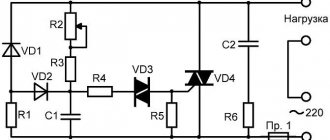
Device diagram
The simplest version of the circuit, designed to work with any load. Traditional electronic components are used, the control principle is phase-pulse.
Main components:
- triac VD4, 10 A, 400 V;
- dinistor VD3, opening threshold 32 V;
- potentiometer R2.
The current flowing through potentiometer R2 and resistance R3 charges capacitor C1 with each half-wave. When the voltage on the capacitor plates reaches 32 V, the dinistor VD3 opens and C1 begins to discharge through R4 and VD3 to the control terminal of the triac VD4, which opens to allow current to flow to the load.
The opening duration is regulated by selecting the threshold voltage VD3 (constant value) and resistance R2. The power in the load is directly proportional to the resistance value of potentiometer R2.
An additional circuit of diodes VD1 and VD2 and resistance R1 is optional and serves to ensure smooth and accurate adjustment of the output power. The current flowing through VD3 is limited by resistor R4. This achieves the pulse duration required to open VD4. Fuse Pr.1 protects the circuit from short circuit currents.
Triacs should be selected according to the load size, based on the calculation of 1 A = 200 W.
Elements used:
- Dinistor DB3;
- Triac TS106-10-4, VT136-600 or others, the required current rating is 4-12A.
- Diodes VD1, VD2 type 1N4007;
- Resistances R1100 kOhm, R3 1 kOhm, R4 270 Ohm, R5 1.6 kOhm, potentiometer R2 100 kOhm;
- Capacitor C1 0.47 µF (operating voltage from 250 V).
Note that the scheme is the most common, with minor variations. For example, a dinistor can be replaced with a diode bridge, or an interference-suppressing RC circuit can be installed in parallel with the triac.
A more modern circuit is one that controls the triac from a microcontroller - PIC, AVR or others. This circuit provides more accurate regulation of voltage and current in the load circuit, but is also more complex to implement.
Triac power regulator circuit
Assembly
The power regulator must be assembled in the following sequence:
- Determine the parameters of the device on which the device being developed will work. Parameters include: number of phases (1 or 3), the need for precise adjustment of output power, input voltage in volts and rated current in amperes.
- Select the type of device (analog or digital), select elements according to load power. You can check your solution in one of the programs for modeling electrical circuits - Electronics Workbench, CircuitMaker or their online analogues EasyEDA, CircuitSims or any other of your choice.
- Calculate the heat dissipation using the following formula: voltage drop across the triac (about 2 V) multiplied by the rated current in amperes. The exact values of the voltage drop in the open state and the rated current flow are indicated in the characteristics of the triac. We get the power dissipation in watts. Select a radiator according to the calculated power.
- Purchase the necessary electronic components , heatsink and printed circuit board.
- Lay out contact tracks on the board and prepare sites for installing elements. Provide mounting on the board for a triac and radiator.
- Install the elements on the board using soldering. If it is not possible to prepare a printed circuit board, then you can use surface mounting to connect the components using short wires. When assembling, pay special attention to the polarity of connecting the diodes and triac. If there are no pin markings on them, then test them using a digital multimeter or a “dragstick”.
- Check the assembled circuit with a multimeter in resistance mode. The resulting product must correspond to the original design.
- Securely attach the triac to the radiator. Don’t forget to lay an insulating heat transfer gasket between the triac and the radiator. The fastening screw is securely insulated.
- Place the assembled circuit in a plastic case.
- Remember that there is dangerous voltage at the terminals of the elements.
- Turn the potentiometer to minimum and perform a test run. Measure the voltage at the regulator output with a multimeter. Smoothly turn the potentiometer knob to monitor the change in output voltage.
- If the result is satisfactory, then you can connect the load to the output of the regulator. Otherwise, it is necessary to make power adjustments.
Triac power radiator
Control signals
The triac is controlled not by voltage, but by current. To open the gate, a certain level of current must be supplied. The characteristics indicate the minimum opening current - this is the required value. Usually the opening current is very small. For example, to switch a 25 A load, a control signal of about 2.5 mA is supplied. Moreover, the higher the voltage applied to the gate, the faster the junction opens.
Voltage supply circuit for controlling a triac
To switch the triac to the open state, voltage must be applied between the gate and the conventional cathode. Conditional, because at different times, the cathode is one power output, then another.
The polarity of the control voltage, as a rule, must be either negative or must coincide with the polarity of the voltage at the conventional anode. Therefore, a method of controlling a triac is often used in which a signal is supplied to the control electrode from a conditional anode through a current-limiting resistor and a switch. It is often convenient to control a triac by setting a certain current strength of the control electrode, sufficient for unlocking. Some types of triacs (called four-quadrant triacs) can be triggered by a signal of any polarity, although this may require more control current (namely, more control current is required in the fourth quadrant, that is, when the voltage at the conventional anode has a negative polarity, and at the control electrode - positive).