How to make a gearbox for a walk-behind tractor with your own hands
Making a gearbox for a walk-behind tractor with your own hands is a difficult and at the same time interesting task. This is one of the important mechanisms, without which the operation of garden equipment using a walk-behind tractor is unthinkable. Its main task is to reduce the speed of the drive shaft and at the same time increase or decrease the torque to the drive.
You can buy a transmission mechanism for your walk-behind tractor in a specialized store, but it is wiser to assemble the gearbox yourself, taking into account all the technical characteristics of the engine. This will be the best option, since when designing a mechanism for a specific power plant, an individual calculation is made, which will simplify the task of pairing it with the engine.
Angular gearbox: device, purpose and principle of operation
Gearboxes are installed on various mechanisms. These can be large ships and a small boat; mechanisms for agricultural machinery and cars are equipped. Inexpensive units are equipped with one-piece, maintenance-free gearboxes. Therefore, you can extend the life of your irreplaceable assistant with your own hands at low cost.
Powerful devices and small gearboxes have the same structure and operating principle.
Gearbox manufacturing process
First, the parameters of the power plant are calculated. The crankshaft speed can be found in the technical specifications.
This is the first quantity required to perform the calculation. The value is not constant, with the addition of “gas” the number of revolutions increases. Basic value: idle speed +10% .
Next, the suspension axle revolutions are calculated . Knowing the size of the wheels, it will be possible to calculate the amount of run-out per revolution. The number of axis revolutions is calculated to ensure a comfortable speed - 3-5 km/h, which is the second value for design.
For example, idle speed +10% is 600 rpm. The required wheel axle speed for 3 km/h is 200 rpm. So, the gear ratio should be 3:1 . The rotation speed of the axis is reduced by three times in relation to the speed of the motor shaft, and the torque increases accordingly by three times. Gearbox types:
Features of creating an angular gearbox with your own hands
Assembling a conical unit is realistic for a person who has certain skills and ability to work with tools. Typically, owners of agricultural machinery have these qualities. You should start working by calculating the rated power. The gearbox for a walk-behind tractor must have power, which is calculated using the formula Pn = P1 x FS, where:
- P1—input power, kW;
- FS is a coefficient characterizing reliability or performance properties.
FS is selected depending on the mode of use of the installation: continuous or intermittent; type of uniform impact load: it can be light or heavy. This calculation will help you find out the angle with the bevel gear. Then the output torque M2 is calculated.
M2 = 9550 x P1 x i x efficiency /100 x n1, where:
- P1—input power value;
- i—gear ratio;
- The efficiency is selected in accordance with the gearbox step;
- n1 — motor shaft rotation speed, rpm.
Since the gearbox for a walk-behind tractor is subjected to axial and radial loads that occur at the ends of its shafts, it is necessary to indicate the possibilities for its safe operation. It is necessary to determine the parameters of the microenvironment, the maximum and minimum temperature conditions, and the type of lubricant. After this, it is possible to begin assembling the gearbox for the walk-behind tractor.
List of necessary tools that need to be prepared for work:
- metal drills, set;
- straight screwdriver and Phillips screwdriver;
- pliers and wire cutters;
- files;
- needle files;
- ruler;
- calipers;
- hammers;
- Workbench;
- rubber gaskets.
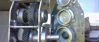
The corner node diagram includes the following components:
- driven gear axis;
- 2 bearings mounted on the driven axle;
- steel housing for these 2 bearings;
- a pulley that carries out V-belt transmission in the cooling system;
- fastening of this pulley;
- fastening the flange directly to the body.
Final drive device
The design of the final drive is so simple that you can assemble it yourself. The basis of the mechanism is a gear that fits onto the splines of a standard drive. The second, driven gear rotates the wheel. To ensure that the direction of rotation does not change, intermediate (parasitic) gears are installed.
Typically the driven gear has more teeth than the drive gear. This allows you to increase the gear ratio and, if desired, equip the car with larger diameter tires.
The same principle applies to heavy tractor gearboxes such as T 170 or truck gearboxes, which are equipped with KamAZ or MAZ commercial vehicles. The only difference is that for tracked tractors and other equipment, the torque is transmitted not to the wheel hub, but to the track sprocket.
If necessary, repairs to the final drive can be done with your own hands. In most cases, to eliminate noise and vibration, it is enough to replace auxiliary elements: oil seals, floating seals, bearings, etc.
Types of gearboxes
There are worm and chain devices. The differences between them are small, but quite important. The difference lies in the characteristics inherent in the two different types: efficiency; angular velocity; number of gears; number of shafts and ratio between gears.
Relatively cheap walk-behind tractors are often equipped with non-separable gearboxes for simplified assembly . In this case, the service life is significantly reduced and additional possibilities are eliminated:
- repair;
- assembly;
- disassembly;
- replacement of parts.
This indicates the low quality of the material used to manufacture the gearbox, and that most of the parts will not be sleeved. The diagram will give an idea of the principle of its operation and service life.
Expensive walk-behind tractors are equipped with gearboxes that are more complex in design and allow further assembly and disassembly. Maintenance can be carried out by correcting all the shortcomings in the operation of the device.
Repairs are carried out in order to extend the service life. It is recommended to replace faulty parts with more expensive ones. Timely lubrication will also extend the service life.
In most cases , the gearbox converts speeds , that is, the angular speed is quickly and efficiently transformed into a low one. There will be a high angular velocity on the input shaft, and a low one on the output shaft.
To prevent unexpected breakdowns, regular high-quality maintenance . When changing speed in steps, the gearbox is called a gearbox. When a step system is not used, the device is called a variator.
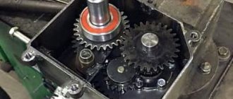
Gears
By means of a gear engagement of two gears, rotation is transmitted from the engine shaft to the gearbox. Gears are cut on special gear cutting machines, so you should make a calculation and buy. The final placement of units and the quality of equipment operation depend on this choice. The number of teeth and gear diameter are two major factors in equipment design.
During installation, it is necessary to maintain the distance between the gears, protecting them from breakage. You should also ensure that the surfaces and teeth are lubricated with gear lubricant. It is poured to the level of the top of the gear, all other parts are lubricated by splashing oil as the gears rotate.
Types of gearboxes
These devices differ in the type of torque transmission.
- Worm gearboxes. The transmission system of these devices contains a worm gear, which allows not only to significantly reduce the speed of the working shaft, but also to change the direction of rotation. The gearbox shaft at the output of the device is usually located at right angles to the input shaft. This feature of worm devices allows the engine to be placed most compactly together with the torque-transmitting mechanism. The gear ratio of this type of gearbox can be up to 1 to 100 or more;
- Gear reducers. Gear mechanisms for torque transformation are often used in units in which it is necessary to implement a different gear ratio between the input and output shafts. A gearbox of this type can be made with one transmission mechanism, or using several gears with a significant gear ratio. The teeth in such devices can have different shapes, but the quality of processing of such parts must be the highest;
- Hydraulic gearboxes. Such devices are installed between the pump and hydraulic mechanisms. A hydraulic gearbox is used for the same purpose as mechanical ones - to reduce the transmitted energy or rotational speed;
- Geared motor. This system is also used for torque transformation and is a gearbox and motor combined in one housing. The most common are gearmotors operating on electric traction. In this case, it is possible to significantly reduce the size of the gearbox and increase the efficiency of the device;
- Planetary gearboxes. The transmission system and planetary type gearbox circuit is a type of gear mechanism, but due to the originality of the applied method of transmitting torque, it can be considered a separate type. Such mechanisms are compact and very reliable in operation, but require precise calculations during production. The teeth of planetary gearboxes must be tightly meshed with each other, but easily set in motion.
The working parts of gearboxes must be lubricated to reduce the coefficient of friction and power loss. The method of applying lubricants depends on the type of gearbox and the power of the transmitted energy. If the transmission system does not operate at high rotation speeds, then a single application of lubricant to the working surfaces during the entire service life is sufficient. For powerful devices, a special system of forced supply of lubricating fluid is used, followed by cooling and cleaning.
Non-separable products, as a rule, operate at low power levels and in those areas where the device is not required to operate in harsh conditions. Gearboxes that are used to transform large capacities are located in a casing of a collapsible design, which allows, if necessary, to carry out scheduled or emergency repairs and adjustments of the mechanism.
The gear housing can be made of various materials. The selection of material depends on the operating conditions and power of the device. The gearbox for low-power household devices can be made of high-strength plastic or aluminum alloy.
Gearbox sliding bearings
The bearing facilitates the rotation of the shafts, removing the friction force through its work. You should remember about the correct selection of this part and proper installation. The sliding support must fit into the seat firmly and forcefully to prevent rotation. It is better to use closed parts. Before installation, it is better to remove the cover and fill the balls and internal support with new grease. When using helical gears or a worm gear, the best option would be to install roller or angular contact ball bearings.
Why use a bevel gear?
A mower is being made for a mini tractor; there is a need to change the direction of the drive shaft by 90 degrees, i.e. you need a bevel gear. Or no reduction at all, or with a slight reduction. What common things can it be used for? It won't work with a grinder. The rear axle of the Ural motorcycle lowers greatly. Maybe agricultural machinery has something like this as standard? Does anyone have experience in manufacturing such gearboxes using automotive differential gears?
I saw something similar on a combine harvester, on this thing in front)) well, where are the knives. The combine in the village is some kind of ancient, either Neva or xs. in general, look for angular gears, they are available in the factory version
off: and here the oil tank builders crawled
Well, if you install a bevel gear with a large reduction, and then increase the speed.
I already thought. but as in the joke: this back and forth annoys me. I would like to avoid unnecessary details... this has already happened a couple of times, you get wiser and wiser, and then you come across a simple solution. Unfortunately, a person’s horizons are not limitless. Right now I’m already thinking about making a turn from two cardans with an intermediate support.
Please note: Original ideas for flower beds made from tires
90 degrees and cardans, well, I don’t know, will they work normally?
turns out 2 at 45 degrees
I saw such a gearbox with a slight reduction in an agricultural machine for sorting potatoes
2Dred Did you decide to come up with a mower for a Lambordini?
On 40s, a drive pulley with an angular gearbox is placed on the rear PTO. In teeth 22-12, if I'm not mistaken..
Yes, my phacelia is blooming, so in a couple of weeks I will need to mow it. Last year, two days of three hours each with a lawn mower did not inspire me; my hand then went numb and did not come off for a month, but this year the area sown has increased.
I tried to find a standard one from the 40, but either the working unit is sold assembled, or it is no longer a gearbox. and the trash...
It turned out that the Ural chainsaw supposedly has an angular gearbox... can anyone explain anything about this? I know where many of these saws are lying without engines.
“Friendship”, “Ural” Electron”, Angular gearbox, gear ratio - 1:2 (I also know where many of these saws are. In the topic “Friendship saw”. There are a lot of them!)
Yes, not supposedly, but it really is worth it, but the gear ratio is about 13
And if you look at the gearboxes of outboard motors? There are so many of them lying around everywhere now. Not very step-down (and if you turn it on the other way around, then step-up), in addition to reverse
there is a gear ratio of approximately 1.5
I’m already thinking about “putting the reduction gear in reverse.” I can only take power from the camshaft, and starting occurs through it, i.e. revolutions from 500 to 1500. For a rotary mower, judging by the characteristics of factory mowers, speeds from 2500 and above are needed. so a 1:3 gearbox will be fine. What do you think about using flanges from a household concrete mixer in a mower? the shape of the disc, there is a seat for the bearing, the diameter is about 500 mm, the price tag is humane and is always available in spare parts.
Here's the device, we'll torture it...
A mower is being made for a mini tractor,
show me what you came up with, maybe we can help you with advice
Yes, I rarely ever make things up, so I decided to stupidly steal the design of an MTZ or forty mower, i.e. a tire made of a channel, on top of it are three flanges of a concrete mixer, we sculpt 3 knives from spring steel onto them, the drive is first with a cardan based on the Ural motorcycle joints through an angular step-up gearbox and then with a motorcycle chain on the sprockets of the flanges, all three are one chain, so the axles of the flanges are not on a straight line, but in a triangle, well, you’ll also have to attach a spring-loaded tensioner. All. The problem is not to invent, the problem is to adapt various standard crap in order to at least bother with a lathe and milling machine. and so that it would be cheap, i.e. crap not from Lexus, it was right now I can throw in a little drawing
LuAZ 969 M › Logbook › Do-it-yourself angular gearbox. It's possible!
Good day.
Today I want to tell you about how I designed an angular gearbox. The idea of making a bevel gear myself arose in my head a long time ago, but this is not an easy task, since it is a rather important component of the car, responsible for traffic safety.
The gearbox must be, first of all, reliable in order to confidently drive around the open spaces and not be afraid that the car will become uncontrollable. Secondly, it is possible to adjust the gear engagement and take out the backlash. Thirdly, be compact, since in my car the space for installing the gearbox is limited. So, after much thought and several sketches of the design of the gearbox, the process of its manufacture was determined, and sketches of the parts requiring turning work were drawn. Based on the sketches, the necessary parts were machined, and the necessary bearings and gears (satellites) were found, which were taken from the UAZ differential.
Here is the entire set of parts for creating an angular gearbox.
Now a little about each component. The threaded bushing is a housing for the bearings; two of them were made; a nut is screwed onto the thread so that the clearance in the meshing of the gears can be adjusted. By the way, the nut was taken from the exhaust pipe of an IZH motorcycle.
A roller on which two bearings and a satellite are placed; a groove was made at the other end of the shaft so that the splines could be fitted and welded. Two of them were also made.
We also made two spacer bushings that are placed between the bearings. Driveshafts, one from a Golf, the other from a Mazda.
From all these parts, two halves of the gearbox were assembled
This is how the two parts form the gearbox.
Then these parts were welded together at a certain angle, which was 65 degrees.
Attached cardan shafts to the gearbox for fitting on a car
Example for a car
To mount the gearbox, a plate like this was made.
Then everything was put on the car and grabbed
The gearbox is almost ready, all that remains is to anoint and close the gears.
I coated the gears with bearing grease...
...and closed the lid on the whole thing.
By the way, I forgot to talk about adjusting the gear gap. The clearance is achieved by tightening the nuts on the bushings, which displace the shafts with gears and bearings along the axis, thereby bringing the gears closer to each other. This is how I resolved the issue regarding the bevel gear. Looking ahead, I’ll say that the gearbox is already on the car, everything turns and turns without any complaints, I haven’t been able to test it on the move yet. I will definitely write the result. I look forward to your comments on this topic.
In the next post I’ll tell you about the pedal assembly and the final part of the steering. All the best!
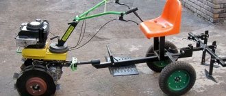
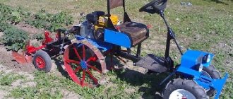
How to make a homemade mini tractor
The simplest option to make a mini tractor with your own hands is to remake a used walk-behind tractor. It contains almost everything you need for construction:
- engine;
- clutch;
- Transmission;
- tractor wheels with axle shafts.
The frame from the walk-behind tractor can be used as a fragment of the frame of a mini tractor. There are mounts for the engine and gearbox. Assembly must be done in the following sequence:
- Weld a frame with all fastening units from rolled metal.
- Install the rear and front axles.
- Secure the engine and transmission elements.
- Assemble the steering.
- Secure the fuel tank, driver's seat, and protective covers.
- Weld a device for installing attachments.
- Conduct electrical equipment and install lighting fixtures.
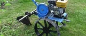
You can take it as a basis. A powerful frame is not required to remake it. A square pipe with a cross section of 100 mm is sufficient. On one side the cultivator itself is attached, and on the other, a steering control with a pedal assembly is installed. The gas and clutch control cables are connected to the pedals. A driver's seat is installed in the middle of the structure. The towbar is welded in the rear part.
Equipment
The converter can be collapsible or non-dismountable. As a rule, budget modifications of walk-behind tractors are equipped with the latter option. Their difference is in less expensive parts that cannot be replaced. If it breaks, you will have to replace the entire gearbox. Manufacturers determine the service life of such models from one to two seasons, no more, provided that the device is used correctly.
More expensive equipment is equipped with a collapsible gearbox, which can be repaired by replacing failed components. Therefore, the service life increases significantly.
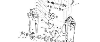
The converter package includes the following items.
- Frame . Depending on the type of gearbox, it may be dismountable or not.
- Rotor shaft , which provides torque.
- Gears of different sizes.
- Chain or belt depending on the type of gearbox.
- With chain transmission, movement is carried out using sprockets - toothed disks .
- With a belt drive, the mechanism is equipped with pulleys onto which the belt is placed.
- Bearings . Since all the parts rotate, it is necessary to reduce friction and ensure that the elements rotate freely. The bearing is designed to cope with this task.
All parts are located inside the case. In addition to the standard set of components, elements for lubricating bearings, for example, an oil pump or a cooling device, can be added inside the device.
Main types, their purpose
A gearbox is equipment that allows the use of an engine in the design of various units. Rotation from the motor is transmitted to the car wheel and boat propeller. In this case, the force increases, with a decrease in the rotation of the motor shaft.
In the household, walk-behind tractors and cultivators are most often used. According to their design features, they can be installed:
- Gear mechanism. Bevel or cylindrical gears are pressed onto the drive shafts. This design allows them to be used in direct transmission of rotation from the engine. Can be used as an angular gearbox for a walk-behind tractor, while the design uses a bevel gear.
- The device is gear-worm. Most often installed with a vertical engine crankshaft. A gear with a certain number of teeth and a worm screw with a certain thread pitch is a schematic description of the type of device. The main feature is the transmission of rotation of the engine shaft at a right angle.
- Chain device. The shafts are equipped with toothed sprockets. They are wearing a special chain, with the help of which torque is transmitted from the motor. For good performance, the chain is tensioned using a tensioner roller.
- Belt device. Rotation is transmitted using belts. Pulleys with grooves for belts are pressed onto the shafts, and the belt is tensioned using a tension screw.
To make a homemade bevel gear, you need to know its operating principle and how to make them at home.
Safety clutch
How to make a scissor lift with your own hands video
It is installed to prevent gearbox destruction during emergency jamming. Can be made in the form of friction clutches or a pin.
You can complete the work of self-assembly and selection of the necessary parts by reading the instructions and recommendations on the Internet.
Most often, it is used to reduce the rotation speed. For example: a boat cannot reach the speed its engine produces. Therefore, an angular gearbox is installed that reduces the propeller speed.
A correctly selected and high-quality bevel gearbox protects your equipment from overloads during operation. Maintenance and timely repair work will allow the equipment to perform its task without accidents and major repairs.
Self-manufacturing of the gearbox - simple about the complex
Each of the listed types of converters has its own disadvantages. Therefore, in order to repair the walk-behind tractor gearbox as rarely as possible, some farmers prefer to equip their equipment with homemade converters. A self-made structure often turns out to be of higher quality and more reliable. To work you will need:
- Phillips and flathead screwdrivers;
- Hacksaw for working with metal;
- Pliers;
- Vise;
- Welding machine.
First you need to weld the body. For this you can use stainless steel plates. Gears and shafts will also be needed for the job. You can “borrow” them from the Druzhba chainsaw. In this case, you will need to drill a hole inside one of the tool shafts. On the opposite side of the gearbox it is necessary to install a second shaft, and after it - bearings and a cage. The output shaft of the device is attached to a pulley. After this, the finished device should be placed in the previously welded housing and machine oil should be poured inside.
The made converter is connected according to the same principle as the standard gearbox. As you do this, pay attention to the position of each gear. The elements should not be skewed, and their teeth should have perfectly straight ends without kinks or other deformations.
Finally, you will need to test the converter. We advise you not to load it immediately after creation. To begin, stretch the wound-up walk-behind tractor along the ground - let the elements of the converter connect and establish interaction. Only after this can the equipment be used for its intended purpose.