Difference between automatic and semi-automatic
The difference between automatic machines and semi-automatic machines is that on a semi-automatic machine the operator performs the following actions:
- installation and securing of the workpiece;
- equipment start-up;
- release and removal of the finished product.
Automatic bar lathes are designed for use in serial and mass production. This is explained by the fact that the design of such machines involves the use of rather complex instrumental settings, which take a lot of time to prepare. Their profitability is achieved only when a large batch of parts needs to be processed.
Options and explanation of modification options
The marking of equipment shows what features it has and its scope of application.
Lathes have a letter and a number name. Letter designations characterize its design features: level of automation, degree of processing accuracy, modification, type of CNC.
Meaning of letters in device markings:
- C – special accuracy.
- B – high accuracy.
- N – normal accuracy.
- A – particularly high accuracy.
- P – increased accuracy.
The numbers indicate:
- the first digit 1 indicates that it is a lathe;
- the second digit indicates the device type;
- the third and fourth show the processing features.
For example, 16K20T means:
- 1 – lathe;
- 6 – frontal type;
- 20 – 200 mm main parameter;
- T – modified.
Classification
Automatic and semi-automatic lathes are classified as follows:
- according to idle and working modes;
- by the number and location of spindles;
- by type of workpiece;
- as intended.
By purpose
- Universal . They are intended for performing turning and other operations on various elements.
- Specialized . Used to perform certain operations on certain elements.
The semi-automatic machine is intended for the manufacture of elements only from piece blanks.
Mostly in the cartridge (cartridge-mounted semi-automatic machines), less often in the center. In automatic bar machines, a rod is inserted into a hollow spindle and subsequently fed and clamped automatically for each part being manufactured.
In magazine machines, blanks are loaded into a hopper or magazine, and from there they are automatically fed to the clamping device of the machine.
By spindle location
- Devices with a vertical spindle.
- Device with a horizontal spindle.
By number of spindles
- Single-spindle . Can only process one element at a time.
- Multi-spindle . Can process multiple elements simultaneously. The number of elements is equal to the number of spindles or one less.
The history of the appearance of a multi-spindle vertical semi-automatic lathe
The appearance of multi-spindle vertical semi-automatic lathes was preceded by a rather long history.
The American Civil War (1861-1865), which created a labor shortage, required automation of production. Then the first automatic machine appeared. K. Vipil created an automatic machine for processing wood back in 1842, and in 1876 Chr. Spencer automated the lathe. His namesake, the English engineer S. Spencer, built his own automatic lathe back in 1860. The multi-spindle machine (in which a product automatically passes through a number of positions and at each of them is subjected to one or more processing operations) appeared in 1895. On the eve of the First World War, automated lathes appeared, on which the workpiece passes sequentially through six to eight positions, and at For each of them, the workpiece is subjected to different turning operations. This machine is known as Bullard's "Multomatic" (Fig. 1). Rice. 1. Bullard's "Multomatic"
Single spindle machines
Single-spindle machines have different varieties. The most common automatic machines are single-spindle bar type ones. These include:
- automatic turning-turrets;
- longitudinal turning;
- shaped-cutting.
Shaped-cutting
Shaping and cutting machines are designed for the production of short parts with a small diameter, which have a simple shape. The material is fixed in a spindle, which rotates using a collet chuck. The machine has 2 or 4 supports , which move only in the transverse direction and carry cutting and shaped cutters.
To obtain a part of the required length, the machine has a movable stop, which is automatically installed after the end of the cycle along the spindle axis. The material is fed using the feed mechanism until it comes into contact with the stop. The main movement of such machines is the rotation of the spindle and the feed movement - the movement of the transverse supports. Some models of shaping and cutting equipment have a longitudinal support that moves along the axis of the spindle and allows holes to be drilled.
Longitudinal turning
This equipment is intended for the production of large quantities of elements from coil or rod of small diameter, but long. Such equipment is used in precision industry enterprises (instrument making, watchmaking, and others). High demands on surface cleanliness and precision of parts determined a number of design features of such machines.
The workpiece is secured in a rotating spindle using a collet chuck. The spindle head moves along the guides of the frame, imparting a feed movement to the workpiece relative to the stationary cutter, which is fixed in the support. Support for the cutter - adjustment movements when switching to processing a step of a different diameter and the movement of the transverse feed during shaped turning and cutting. The machine has a balanced type support and two or three vertical supports. A balanced-type caliper carries two cutters and performs a rocking motion around an axis that is fixed in the bracket. To increase the rigidity of the system, the rod (workpiece) moves in a steady-state bushing. Threading, reaming, countersinking, drilling can be carried out using special devices that are installed opposite the workpiece being processed.
Often the spindles of these devices have independent drives for translational and rotational movements.
Turning and turret
These devices are turret lathes, which are intended for the production of parts of complex shapes. These machines are mainly designed to perform work from rods, but some models can also process piece products. The rod is fixed in a rotating spindle .
The turret makes automatic movements that are associated with the longitudinal feed, including automatic rotations for changing tools. Cross feed is carried out by two or three supports. The operating principle and design of such equipment are studied in laboratory conditions.
Parallel action semi-automatic devices
Parallel-action semi-automatic machines are also designed according to a similar scheme, on all spindles of which, unlike sequential-action semi-automatic machines, identical operations are performed simultaneously and in one cycle of work the processing of as many workpieces is completed as the number of spindles the machine has. Such a machine has a base 5 (lower block) installed a fixed vertical column 4, around which a table with spindles and a hexagonal sleeve with six supports 2 continuously rotate, representing a single whole - carousel 1 (Fig. 5).
Rice. 5. Scheme of operation of a vertical multi-spindle semi-automatic machine : 1 - carousel; 2 — caliper; 3 - drum; 4 - column; 5 - base.
When the liner is rotated, the calipers move along its vertical guides from the stationary drum 3 (upper block), with which they are connected by rods. In a semi-automatic machine, each spindle has its own support, from which the part is processed while the carousel rotates. In one full revolution of the carousel, each spindle passing through the loading zone completes the processing of the part. In this zone, the spindle rotation is first automatically switched off and the part is released from the clamp, and the corresponding support quickly moves up, the finished part is removed and a new workpiece is installed. Then it is automatically clamped, the spindle is given rotation, and the support is quickly brought to the workpiece. Modern semi-automatic machines of this type have four or more working spindles.
Multi-spindle machines
This equipment is divided into two types:
- parallel action;
- sequential action.
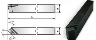
The camshaft is a characteristic part in semi-automatic and automatic lathes.
Cams of various shapes and designs are mounted on it (depending on the purpose). They control all auxiliary and working movements of machine tools through a system of mechanical and other connections. The most commonly used cam designs are:
- drums _ They are designed to control auxiliary and working movements of machine tools. It is a cylinder that is equipped with overhead cams or shaped milled grooves;
- disk _ They are needed to set the working parts of semi-automatic and automatic machines in motion - calipers and turrets.
Discs with end-mounted cams are used only to activate auxiliary movements (rotation of the turret, clamping and movement of the rod, etc.). The discs have a separate scale. Most often it is divided into hundredths of revolutions. This scale is necessary to install the cams in the right place.
Multi-spindle horizontal
They are needed for processing elements from calibrated rods of hexagonal, square and round profiles, as well as from pipes in mass and large-scale production of various branches of mechanical engineering.
The main technological operations performed on this equipment are:
- shaped turning;
- thread rolling;
- segment;
- thread cutting;
- deployment;
- drilling;
- grinding.
All necessary movements in the equipment occur automatically with the help of cams, which are located on the camshaft. With one revolution, a full range of movements of the device mechanisms occurs , which is necessary for the production of one processed element. This complex determines the processing cycle, and the cycle time is the period during which one revolution of the camshaft is made.
In a multi-spindle horizontal bar device, the spindles are arranged in a spindle block along a circumference. Transverse supports are located at the end of the spindle block, and the longitudinal support can move on the central sleeve. The spindles of the device receive rotation from the central shaft through gears. After the finished product is cut, the spindle block is rotated at an angle that corresponds to the number of spindles.
Kinematic diagram of a vertical multi-spindle semi-automatic machine of sequential action
The kinematic diagram of one of the seven sections of the main movement and feed drive (the other six sections are similar), as well as the drive and mechanism for rotating the table with spindles is shown in Fig. 3 33
During the main movement, the working spindles VIII receive high rotation speeds from the electric motor M1 (N = 10 kW; n = 1460 min-1) through the gear 16-39 • 39-118 • 118-31, and low speeds through the gear 16-39 • 22 -39 • 22-39 • 39-118 • 118-31 and further from shaft V through replaceable wheels ab, cylindrical pairs of wheels 35-40 and 37-50 (for high-speed versions - through a pair of wheels 37-37). A gear wheel with z = 35 during table rotation is disengaged from a wheel with z = 40, and after rotation it engages with the same gear wheel of another spindle that has come to this position. After each indexing of the table, the spindles acquire the rotation speed of the position in which they crossed. The rotation speed of the spindles in each position is regulated by its own setting link a - b. Synchronizers ensure a smooth, shock-free start of rotation of the spindle in each position. Each spindle, starting with shaft V, has an individual drive chain, but identical with the chains of other spindles. There are as many of these chains as there are working positions (the 1K285 machine has seven of them). The brake that stops the loading position spindle has a mechanism that is activated by a drive common with the synchronizers, engages with the conical cups of the pre-spindle shafts and is similar in design to the synchronizer, but has no rotating elements.
Rice. 4. Kinematic diagram of a vertical multi-spindle semi-automatic lathe model 1K285
The chains of working feeds and rapid movements of the caliper are concentrated in the feed boxes. Using electromagnetic friction clutches built into them, the feed speed is switched from high to low or vice versa (in a ratio of 2.63 times).
The working feed of the calipers is carried out from shaft VI through the worm gear 1-32, a set of replaceable gears cd e-f and then through gears 35-62 (when the electromagnetic clutch EM1 is turned on) or through wheels 58-39 (when the electromagnetic clutch EM2 is turned on ) on shaft XIII. From this shaft, through bevel gears 27-38, rotation is transmitted to the caliper lead screw nut (P = 12 mm). By switching the EM1 and EM2 clutches, you can automatically set two working feeds of the support (small and large) during the processing of the workpiece.
Accelerated feed of the support is carried out from shaft V through bevel gears 20-20 and a pair of cylindrical wheels 70-40 to shaft X. Further, with accelerated supply of the support to the workpiece (electromagnetic clutch EM3 is turned on), rotation is transmitted through gear 57-39 • 38-59 • 27-38 on the caliper lead screw nut. With accelerated retraction of the caliper (electromagnetic clutch EM4 is turned on), rotation is transmitted to the lead screw nut through gears 58-31 • 31-38 • 38-59 • 27-38. In the rapid feed chain, it is possible to reverse the direction of movement by switching on different kinematic chains using two clutches.
Electromagnetic fast-speed clutches of the caliper are interlocked with the same working feed clutches. The clutches are activated using limit switches installed in the control device.
The rotation of the command apparatus shaft is carried out from shaft XIII through a helical gear drive 18-13 and a worm pair 1-66. The command device controls the working and auxiliary strokes of the caliper in the automatic and adjustment cycles. In addition to the limit switches, its body contains a cam shaft and levers. Limit switches do not have springs, which is why the command given to them is remembered until the next press.
After completing the working operations in all positions and retracting all the supports to the upper position, a command is given to turn off the drive of the electric motor M1 and braking the entire system, followed by rotation of the table.
The table is rotated by the M2 electric motor (N = 2 kW; n = 1300 min-1) through a 1-25 worm gear, 14-105 gears and a Maltese cross. A bar with two rollers is installed on the hub of a gear with z = 105. When you turn the wheel with the bar, the rollers fit into a groove on the bottom of the table, turning it. When the bar is rotated 180°, the table rotates one position (1/8 of a turn), and when rotated 360°, it rotates by two positions at once (1/4 of a turn). After the table is rotated, but before the spindles turn on, it is locked.
The table rotation and fixation mechanism is controlled by the action of two cams 2 on the limit switches of the table indexing command apparatus. The cams are mounted on shaft XXII, which receives periodic rotation through gear 105-15 • 4-28.
At the end of the table rotation, the electric motor M2 is turned off and the starting clutch of the main drive motor M1 is turned on.
The machine is equipped with an automated hydraulic device for clamping the part, has a mechanized loading device and a chip removal system. The machines in the six-spindle version are available with chuck diameters of 630 and 800 mm, in the eight-spindle version - 250 and 400 mm.
In addition to the five types of supports already mentioned, special supports can be supplied with the machine upon request, which are a modification of the universal one and allow you to expand the technological capabilities of the machine - to perform:
- processing of longitudinal shaped surfaces using a copy machine;
- processing cones using a cone ruler;
- processing of cylindrical surfaces with rebound at the end of the working stroke;
- machining the end surface simultaneously with the conical surface;
- boring of spherical surfaces
Among the various devices that are equipped with a semi-automatic machine, the most complex is the kinematic chain of the drive of a multi-spindle drilling head. When the head is used, an additional gearbox is attached to the feed box of the corresponding position.
Automatic longitudinal turning
An automatic longitudinal turning machine is one of the types of specialized turning equipment, included in the classification group “Automatic and semi-automatic lathes”. Such equipment is used in the mass production of high-precision small-sized parts such as rotating bodies. In catalogs of production equipment (especially foreign ones), a different name is used for these machines - “Swiss-type lathe”.
This is due to the fact that lathes with longitudinal movement of the spindle head and a fixed support were created at the end of the nineteenth century by Swiss watchmakers. For more than a hundred years, the basic layout and operating principle of such machines have not changed at all, but at the same time they have received many additional capabilities. Currently, one of the most common types of such equipment is a CNC automatic longitudinal turning machine, which, in addition to traditional fixed supports, usually includes a counter spindle and several positionable blocks of driving and cutting tools.
Varieties and design features
There are actually a lot of machines and they perform all kinds of metal processing operations, but we will highlight the most famous types
Multi-incisor
Designed for processing complex parts made from pipes, shaped profiles or rods of different sections. Multi-cutter or multi-spindle machines are mainly used in batch production.
Performed operations:
- drilling;
- thread;
- turning;
- pruning;
- boring;
- countersinking;
- deployment.
Multi-cutting machines have high productivity due to the large area of the drive mechanism, rigidity of the structure, and the ability to perform several operations simultaneously.
Carousel
A group of machines for working with large-sized parts and workpieces. The parts processed on them are short in length, but have significant weight and diameter.
Features of carousel models:
- used for processing conical or cylindrical surfaces;
- grooves of various configurations are made;
- You can also do grinding, milling, trimming ends;
- thread cutting.
In addition to the basic elements of any lathe, this type has additional equipment:
- table with faceplate;
- racks for moving the traverse.
Backing
The machines are designed for processing the back surfaces of tool teeth. It can also be used to perform other turning operations. The backing machine is distinguished by its special support design. The part is backed up as follows:
- rotational movement of the part;
- reciprocating movement of the cutting tool towards the part.
Screw-cutting
The most common group of machines. Widely used in serial and individual production. Screw-cutting models can be found in workshops, schools, and in any industry. They are easy to operate and maintain.
REFERENCE! The screw-cutting lathe is a universal model for all kinds of processing of metal workpieces. It can be used to make various types of threads: modular, inch, metric.
Structural elements:
- bed;
- front and rear stock;
- caliper;
- apron;
- gearbox.
Revolver
Revolver group machines are designed for processing parts from calibrated rods. Operations that can be performed on this equipment:
- turning;
- boring;
- shaped turning;
- countersinking;
- drilling;
- thread formation;
- deployment.
REFERENCE! The name of the machines in this group comes from a special holder. It can be driven or static. The drive type gives more possibilities for carrying out various operations.
Universal
Universal lathes include screw-cutting machines, since they can perform almost any metal operation.
Main technical characteristics of the universal machine:
- rotation speed (number of revolutions); accuracy class; it is indicated in the product labeling with the letters S, B, N, A, P;
- number of gears;
- what sizes of parts can be installed;
- weight and dimensions of the machine;
- the amount of feed and maximum movement along the axis.
Equipment design
Traditionally, in lathes, the forming movement is the rotation of the main spindle, and the feed movement is the movement of the support in the direction opposite to the rotation axis. With such a cutting process scheme, a number of design difficulties are inevitable in ensuring rigidity, vibration resistance and positioning accuracy of the caliper, especially when processing high-precision parts at high speeds. To solve this problem, Swiss designers found a non-standard and revolutionary solution for those times. They created a manual lathe (and then an automatic lathe), in which the support with the tool is stationary, and the feed movement is carried out by a movable spindle head in the direction of the rotation axis (i.e., the rotating part slides onto a stationary cutter).
Although the CNC automatic longitudinal turning machine differs significantly in its production characteristics from the first machines of this type, it has the same traditional layout and composition of the main components and assemblies:
- solid cast bed with guides for the headstock;
- movable headstock with a hollow spindle and collet clamp;
- steady bushing;
- block of fixed supports with cutters;
- device for feeding bar blanks through a spindle.
A modern automatic lathe is a multifunctional machining center with numerical control. In addition to traditional components, such equipment may include:
- counter spindle;
- block or turret with driven tool;
- cutter blocks positioned in different planes;
- supplies store;
- parts catcher and conveyor for finished parts;
- coolant supply system;
- chip removal conveyor.
On machines of this type, it is possible to perform independent processing with cutting and driving tools simultaneously of two parts fixed in the spindle and counter-spindle. In addition, precise synchronization of spindle rotation makes it possible to transfer the workpiece being processed from one spindle to another, which allows processing of both ends of the part in one installation. And the presence of a turret head and various blocks of cutting and driving tools makes it possible to perform the entire range of necessary technological operations on one part installation: from turning, drilling and threading to flat and contour milling.
The specific features of automatic longitudinal turning machines include high requirements for the quality of workpieces.
It is believed that the accuracy of the processed rod, profile or wire should be of a higher quality than the part obtained from them. Another feature is the need to use non-rotating steady rest bushings, which are prone to wear and heat, to improve processing accuracy.
The main components that make up a metal lathe
Any metal lathe includes basic structural components and elements.
bed
The main and largest element on which all other parts are attached. This is a stationary part, consisting of two parallel walls, fixedly connected to each other by crossbars. The bed has cabinet legs in which the tool is stored.
The top rails serve as guides along which the lathe support and tailstock move. They can be flat or prismatic. The guides are made strictly parallel to each other.
Headstock
This part may also be called a spindle head. Inside it are the following parts:
- spindle;
- bearings (two);
- pulley;
- gearbox.
The headstock supports the workpiece and gives it rotation.
Spindle
The spindle is the main part of the headstock. It is a cone-shaped metal shaft. It holds various tools, mandrels and other devices.
The lathe spindle, journal and bearings must be smooth, cleanly ground, without backlash, because this affects the quality of boring parts. The spindle has a thread, and in some machines it also has a special groove so that the chuck does not unscrew spontaneously.
Transverse and longitudinal feed mechanism
The caliper can move lengthwise and crosswise thanks to the feed mechanism. The direction is set by a snaffle located in the headstock housing. There are handles on the outside of the machine that can be used to change the direction and amplitude of movement of the support.
Important!
Caliper
A support is a characteristic element of any lathe, with the help of which the cutting tool moves in the longitudinal, transverse and inclined directions. The longitudinal movement along the frame slide is carried out by the carriage, and the transverse movement is made by the upper part of the support. Tool holders (single or multiple) are installed in the upper part of the support.
Apron
Behind the apron body there are mechanisms connecting the caliper with the rack and lead screw. The apron control is located on the machine body, which simplifies the adjustment of the caliper stroke.
Tailstock
The tailstock is where the part is attached to the spindle, so this element is movable. The part consists of two parts: the lower one – the plate and the upper one – the spindle holder. The tailstock of the lathe moves along the bed and can be locked anywhere thanks to the lever handle. The cone of the tailstock is called a quill. A tool or device is attached to it. The tailstock also serves as a second support when processing long parts.
Carriage
The carriage is designed for longitudinal movement of the caliper along the bed slide. The free movement of this element depends on its serviceability.
Shaft
The spindle rotation shaft has two switching handles. When the handles are in the middle position, it is turned off. Up position – the shaft rotates counterclockwise (working movement), down position – the shaft rotates clockwise (reverse movement).
Application of automatic longitudinal turning machines
Automatic longitudinal turning machines are used for the serial production of small-sized cylindrical parts of high precision from calibrated rods, shaped profiles and wire. Their productivity can reach several dozen finished parts per minute. The ranges of geometric dimensions of these products are usually: diameter - 1-60 mm, length - 5-300 mm, and quality characteristics - sixth to eighth quality in diameter and at least eighth quality in length. Typical examples of such products are shafts, bushings, axles, crossbars, collets, hollow cylinders and precision threaded products for precision mechanisms.
Classification of automatic lathes
Automatic and semi-automatic lathes are a separate group of turning equipment designed for high-speed mass production of small-sized cylindrical parts. One of their characteristic features is that many types of this equipment use a calibrated rod or wire as a workpiece, fed into the processing zone through a hollow spindle. The main types of materials processed on these machines are ordinary and alloy steels, aluminum alloys, brass and other copper alloys.
Classification of automatic and semi-automatic lathes is made according to the following criteria:
- scope of application (specialized, universal);
- layout (vertical, horizontal;
- number of spindles;
- principle of feeding and fixing the workpiece;
- type of control (mechanical, electromechanical, electronic with digital drive);
- processing method;
Within classification groups, additional features related to technological features, purpose and types of processing are used. Therefore, single-spindle semi-automatic lathes, simple cam lathes and machining centers with longitudinal turning have identical names, which differ only in the type of control and additional equipment. For example, the full name of one of the groups of modern automatic longitudinal turning machines according to this classification may sound like this: “universal horizontal single-spindle bar longitudinal turning automatic lathes with CNC, counter-spindle and turret head.”
The additional spindle of a longitudinal turning machine is classified as additional equipment, therefore, taking into account the presence of a turret head, it can also be called a “single-spindle lathe-turret longitudinal turning machine.”
A multi-spindle automatic lathe is a machine with a spindle unit consisting of several parallel spindles, which is mounted in the headstock. The total number of spindles in such equipment is from two to six. Two-spindle machines are rare, but the most common is the six-spindle automatic lathe.
In such a lathe, the number of stationary supports with cutters arranged in a circle corresponds to the number of simultaneously rotating spindles. When the block is rotated, each spindle with a workpiece clamped in it moves to the next position to the next support. Each support has different cutters that perform turning on a specific surface of the workpiece. Thus, for six fixed positions of rotation of the spindle block, each of the six parts is processed by different cutters of six supports.
Turret machines
A distinctive feature of turret lathes (Fig. 1) is the presence of a specialized multi-position head. This head is called a turret and has several tool holders. The cutting tool is changed during operation by rotating the turret head to a certain angle.
Figure 1. Turret lathe.
Figure 1. Turret lathe.
The turret lathe structurally consists of the following main parts.
- Bed with base plate and guides. Serves to place machine components.
- Caliper feed box. Designed to set the automatic feed speed.
- Front (spindle) headstock. Contains an electric motor, a gearbox gear system and a spindle drive.
- Cartridge. The workpiece is secured in the chuck.
- Tool holder. Serves to secure a turning tool. Standard lathe equipment.
- Caliper. Creates a feed movement of the cutter into the processing zone. Equipped with a drive screw, which is connected to the feed box. The feed box, in turn, can work in tandem with the gearbox. This allows you to set the automatic feed rate, which depends on the spindle speed. Used for cutting threads or when turning at a precisely specified feed rate.
- Revolver type tool holder. The presented model of the turret machine has six slots that serve to secure axial cutting tools (drills, countersinks, reamers). Also, a regular cutter can be installed in the turret head.
- Revolver head support. Performs the same functions as a standard caliper. It is also connected to the feed box using a lead screw.
- Turret caliper drum.
Today, turret lathes are gaining increasing popularity, especially in the segment of CNC metal-cutting equipment. This is explained by the rather extensive technological capabilities of CNC turret lathes.
Automatic and semi-automatic lathes: purpose and principle of operation
Automatic and semi-automatic lathes are mainly used for turning complex-shaped parts from rods and piece workpieces in large-scale and mass production. An automatic machine is a machine in which all the main and auxiliary movements necessary to perform the technological cycle of processing a workpiece, as well as loading the workpiece and unloading the processed part, are automated. Maintenance of the machine comes down to the periodic supply of material - a workpiece or rod - and control of the processed parts.
Semi-automatic lathes are called lathes in which all the main and auxiliary movements that make up the processing cycle of one workpiece are automated. At the end of the cycle, the semi-automatic machine stops; to repeat the cycle, it is necessary to remove the finished part, place and secure a new workpiece and start the machine again.
Automatic and semi-automatic lathes are designed for the manufacture of parts of complex configurations by processing the workpiece with several tools. Along with automatic lathes and semi-automatic machines, which are most widespread in mechanical engineering, there are automatic and semi-automatic machines for milling, grinding, drilling and others.
Automation of the operating cycle of modern machine tools is carried out using mechanical, hydraulic, electrical and electronics, pneumatics or a combination.
Machines with a mechanical automation base are productive and reliable in operation. However, reconfiguring such machines takes a lot of time. Therefore, automatic machines with a mechanical automation base are used, as a rule, in conditions of mass production, and semi-automatic machines are used in conditions of serial and large-scale production. Machines automated by other methods allow for quick changeover and are therefore most often used in mass production.
A special place is occupied by CNC machines , this is equipment with numerical digital program control of the cycle. Such machines can be effectively used for the production of parts in small and medium series.
Automatic and semi-automatic lathes are divided according to various criteria:
- purpose - universal and specialized;
- type of workpiece - rod and cartridge;
- number of spindles - single and multi-spindle;
- arrangement of spindles - horizontal and vertical.
The production of lathe group machines makes up the majority of the total production of machine tools. The range of their standard sizes is extremely wide: from tabletop to heavy (weighing up to 1300 tons).
Scientific and technical achievements in machine tool building, mechanical engineering technology, theory of metal cutting, radio electronics, electrical engineering, as well as in the field of creating automatic control systems have created conditions for the production of a new class of machines in terms of automation level - high-performance metal-cutting machines equipped with a numerical program control system.
Automatic and semi-automatic lathes are high-performance machines that are widely used in large-scale mass production. These machines should be considered as program controlled machines on a mechanical basis. The main control element of such machines is the camshaft, on which there are cams that control the individual mechanisms of the machine, ensuring reliable synchronization of all movements of the machine’s operating cycle. In this case, the cams (copiers) are the carriers of the operating program of the automatic or semi-automatic device. Therefore, such machines are often called cam machines. It is necessary to skillfully use this complex technological equipment in mechanical shops of machine-building plants in order to ensure maximum removal of parts from the machine with minimal time, with high precision of manufactured parts.
Vertical multi-spindle semi-automatic device of sequential action
The schematic diagram of a six-spindle semi-automatic machine with sequential action (Fig. 3) includes a base 1 with an installed fixed hexagonal column 5, around which a table 2 with six spindles 3 periodically rotates. Five supports 4 serve five spindles simultaneously. The workpiece is installed in a loading position that does not have a support. After the table is rotated 60°, the spindle begins to rotate and the part is processed in position I. At the end of the first operation, the table rotates again, moving the workpiece to position II, etc. Thus, a certain operation is carried out in each position and, at the end of processing, into the loading The finished part arrives in position. The machine drive consists of an electric motor 7 and a gearbox 6. In general, the machine is composed of three blocks: upper, middle and lower. The upper block contains an electric motor 7 with a gearbox 6 and five gearboxes 8 and feeds, command devices 9, etc.
Rice. 3. Schematic diagram of a six-spindle semi-automatic sequential action
In the middle block, on a hollow column, initially having a prismatic shape, then cylindrical, turning into a cone, components are mounted that determine the accuracy of the machine and its rigidity: guides, supports 4, a rotary spindle table 2 is based. Position drive shafts 10 pass through the cavity of the column, and also a pull rod for the brake and synchronizers 11. On the lower bowl-shaped base block there are synchronizers 13, a brake, a gearbox, a table rotation mechanism and a lock 14, a coolant pump, an electrical cabinet 12, an oil tank and other mechanisms. A rotary spindle table is centered on the hardened conical surface of the column.
Working position command devices are used to control the initial position of the support, control its rapid approach and switch to the working feed and change it during processing, quickly withdraw and control the overload of the support.
The spindle speeds at different positions can be different, and after rotating the spindle table to a new position, the spindle must receive the speed set for this position. For shock-free connection of the gear wheels rotating the spindle with the main drive, a synchronizer is used. The brake stops the spindle, which continues to rotate by inertia, after it has been rotated to the loading position, then releases it, allowing it to rotate when installing the workpiece manually. The spindle table carries spindles with chucks or installation devices and securing workpieces and serves to transport spindles from one position to another. The thrust bearing of the spindle table affects the processing accuracy, reliability of the table and maintaining the position of the spindles under the influence of cutting forces.
The rotation mechanism of the Maltese-type spindle table and the collet clamp ensure smooth indexing and shock-free pairing of the stopper and the table. The table indexing command device is used to adjust the angle of rotation of the table for single or double indexing, determine its position at which loading and processing are permissible, set command points for the end of rotation and turning on the spindles and the clamp, as well as to control the position of the clamp.
Standard calipers allow you to perform the most common types of processing. All main five types of supports are mounted on column guides and provide:
- vertical - vertical movement of the tool, has the simplest and most rigid design;
- universal - longitudinal vertical, and then horizontal or angular movement;
- parallel action - processing of a part by two groups of tools, one of which has vertical movement, and the other - sequentially vertical and horizontal. This support is the least rigid and is used when there is a lack of working positions;
- a support with a drilling head drive - processing off-center holes with planetary heads without stopping the spindle;
- caliper with boring head - finishing of central holes with a diameter of 20 to 100 mm.
Multi-spindle semi-automatic lathes are widely used in large-scale and mass production because they have wide technological capabilities in the manufacture of a variety of parts and provide a high degree of processing concentration. The use of such machines helps to increase labor productivity, reduce machine intensity, reduce production space, and simplify transport connections.
Vertical multi-spindle semi-automatic machines are used for processing relatively large parts in a chuck or fixture, less often in centers. A large number of working positions (usually 6-8) allows them to be used in different combinations. Parts of complex shape are processed at all positions of the machine, moving in the next cycle to the next position (single indexing). For simple parts that can be processed at a small number of positions, more productive parallel-sequential processing is used. There are several options: most often the machine is used as two parallel working machines, turning the table into two positions in each cycle (double indexing). You can process two parts on one side or one, but on both sides, you can process two different parts.
The machines are available in power and speed versions.
Setting the cutting modes—spindle rotation speed and caliper feed speed—is performed by installing replaceable gears and making corresponding switches on the feed boxes. Coordinates for changing the speed and direction of movement of the caliper with an accuracy of 0.3. . . 0.5 mm are adjusted by position controllers using cams. Additionally, rigid stops are used at the end of the stroke. The size of the product is finally adjusted by adjusting the tool.