Cutting edges for welding
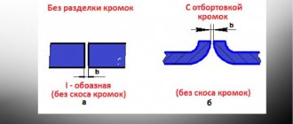
To obtain high-quality welds, it is necessary to cut the edges of the parts. Grooving is a change in the geometry of the edge of a part. Simply put, the end of the part is cut off at a certain angle on one or both sides.
The angle and shape of the groove are determined by a regulatory document, most often this is GOST for the type of welding that will subsequently be used to connect the parts. Most often this is GOST 5264 (for sheet and profile products) and GOST 16037 for pipes.
Why is edge cutting done when welding?
Edge cutting is carried out in cases where it is necessary to weld parts with a thickness of more than 3-4 mm. Thinner parts can be welded without cutting, since the arc will melt metal of such thickness. The cutting of the edges ensures uniform filling of the cross-section of the parts with filler (electrode) metal.
In simple terms, edge cutting is necessary to weld the parts and not leave unfused areas. It provides a smooth transition between the weld and the base metal. The latter, in turn, reduces the stresses that appear in the metal during welding as a result of heating.
Edge bevel angle
As already mentioned, the bevel angle is determined by the regulatory document. The most commonly used angle is 45 degrees at connections such as C8, C9, C10, C11 and C12, C15 and C43. Also an angle of 25 degrees at connections C17, C18, C20, C21, C25, C39, C45. The designations are taken from GOST 5264. These are the 2 most common edge cutting angles for sheet structures and profile structures.
If we talk about the pipe, then the most common cutting angles are 30 degrees used in such connections as: C17, C18, C19, C46, C49, C50, C51, C54, C55, C56 and a less common angle of 50±3 degrees which is used in compounds C8, C10, U15, U17, U8, U19, U20, U21.
Types of edge preparation
Let's consider all types of edge cutting that are found in regulatory documents for welding.
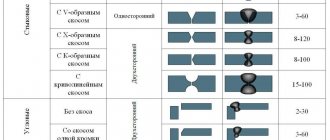
V-shaped
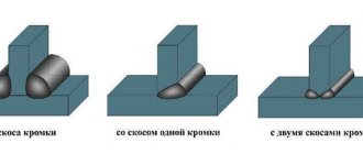
The V-shaped edge groove is the most common and easiest to perform. The ends of the parts are ground down and when viewed in cross-section, the edges seem to create the outline of a Latin letter - V.
When performing such cutting, the edges are also blunted, which prevents burning and leakage of the weld pool metal.
X - shaped
Now let's consider this type of cutting as an x-shaped cutting. It, like the V-shaped cutting, is used quite often. It is actually a V-shaped cut of the upper and lower parts of the part, forming, as it were, the letter X.
It is used in cases where thicknesses exceed 8 mm, this is when welding sheet and profile structures. If we are talking about welding pipelines, then the X-shaped groove is used already with a thickness of 3 millimeters or more (for example, connection C56 according to GOST 16037). Its use provides a less wide seam than if a V-shaped groove was used. This will correspondingly reduce the stress in the weld metal.
U-shaped
U-shaped cutting of edges is used in cases where high welding quality is required at the same time (minimal welding deformation design) and at the same time the parts being welded have a sufficiently large thickness of 15 mm or more in accordance with GOST 5264. This cutting is most often performed in the factory , it is quite difficult to perform during installation.
K - shaped
The K-shaped edge groove is very similar to the X-shaped one, except that the groove is made on only one wall of the part. It is used for welding products with wall thicknesses from 12 mm up to 100 mm.
Let's make a short summary: V and U-shaped cuttings are done on one side, K and X-shaped ones are cooked on 2 sides. This must be taken into account before starting work and at the design stage, because if there is no access to the reverse side, then there is no point in planning such cutting.
Primary requirements
A quality connection can only be made if certain requirements are met:
- Joints of workpieces are performed exclusively in places to which free access is provided. The requirement is relevant even if the connections are made using additional devices.
- Workpieces are fixed only rigidly, accurately and in the position specified by the project. This will prevent deformations from occurring.
- Changes in product positions are excluded to prevent the formation of distortions.
- Any process is planned in advance so that each subsequent operation is carried out without difficulty.
It is also necessary to observe safety precautions when preparing metal for welding, since during such work dangerous tools are often used, including an angle grinder (electric angle grinder).
In preparation for welding, the following activities must be performed:
- check that the electrical network allows you to connect the welding machine and is able to withstand its load;
- make sure that the power cable has proper insulation;
- check the complete serviceability of all auxiliary equipment, some of which are especially dangerous (grinder).
It is also necessary to take care to protect the eyes from electric arc radiation. For this purpose, special masks, glasses and welder shields are used. The respiratory organs are also subject to protection. This is especially true if work is carried out indoors. To protect the respiratory system from harmful gases, masks with special filters are used. It is also necessary not to forget about overalls, including leggings, boots, fireproof jackets, overalls, trousers and other similar things.
Absolutely all preparatory operations preceding the welding of parts are carried out in accordance with the technical conditions determined by the technology.
Advice! After completing the creation of a metal structure, it is necessary to check the seams and dimensions of the finished product, which must correspond to the calculated dimensions.
Designations on the drawings
The main types of edge preparation for welding are not indicated in the drawings. When designating a weld seam, the drawing indicates the regulatory document in accordance with which the seam is made, as well as the type of connection itself, its symbol. You can read more about how welding seams are designated in a drawing in our article - How welding seams are designated in drawings - welding symbol.
Bottom line
To understand how to properly clean welding seams, you need to familiarize yourself with GOST, which describes in detail the technology for processing joints. There are two main methods for cleaning a weld seam: mechanical treatment and chemical treatment.
In the first case, the metal, for example stainless steel, is subjected to grinding and polishing. In the second case, etching and passivation technology is used. Special solutions are used to pickle stainless steel after welding. Most often, these methods are combined to achieve the best results.
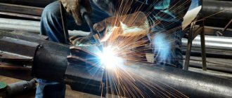
Preparation of edges for welding
Cutting is carried out mechanically or thermally. If cutting is carried out mechanically, then most often a grinding machine (angle grinder), special machines - chamfers, using a milling or lathe, and occasionally files are used. If the cutting of edges is carried out thermally, that is, the metal is removed using gas or plasma cutting, air-arc gouging, and then the edges are still processed mechanically. We'll talk more about the equipment later.
Do you know all types of metal welding? Follow the link and check yourself.
Features of cutting methods
When oxyfuel cutting of alloy steels, free carbon forms carbides, which are very difficult to remove. Therefore, the preparation of alloys such as chrome-plated stainless steel, for example, is carried out in other ways. Gas beveling is used mainly for carbon steels.
The quality of manual thermal cutting almost always leaves much to be desired, so it is necessary to additionally treat the cut with abrasive. In addition, the composition and properties of the top layer change, which leads to deformation of the products.
Plasma cutting allows you to get a high-quality cut of almost any metal. Air is used as the plasma-forming gas. Portable thermal cutting devices are equipped with gas and plasma torches. When installing three burners, you can make K-shaped bevels on the edges.
With machine thermal cutting, the quality of the edges is high and meets the requirements of GOST standards. Laser cutting of edges is used when there is nothing to replace it with, it is very expensive.
Mechanical cutting ensures high-quality edge bevels. The advantages include the creation of bevels of complex shapes. But there are also significant disadvantages, including low productivity and difficulty in forming edges on large workpieces.
When forming double-sided bevels using a mechanical method, turning of the workpieces is required. Cutting joints with abrasives is hazardous and requires a lot of manual labor. Abrasive elements cause cracks.
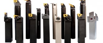
Mechanical cutting equipment
To create a bevel of edges for welding, various equipment is used, ranging from the simplest files to complex automatic systems with program control.
If you want to know what the NAKS registry is and how you can work with it to check your IDs, if so, follow the link.
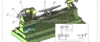
Machine tools
If we are talking about the factory production of parts and blocks, then cutting the edges is most often performed on lathes and milling machines, depending on the configuration of the parts. In installation or small-scale production conditions, manual machines called chamferers are used. Currently, there are a very large number of them, ranging from simple manual ones like “Mongoose” to automated complexes of German and Czech production, for example BDS (made in Germany) NKO Machines (Czech Republic).
Edge cutting machines are divided into edge milling, edge planing, and edge splitting. Edge planers are used only for straight workpieces, but they can be used to produce even curved edges.
Edge milling machines - machines belonging to this group cope with curved surfaces; the working tool is a milling cutter. Often these machines are equipped with CNC. Edge splitting machines are the most highly productive, but the processing is rough and is used for large parts. Afterwards, additional edge processing is required.
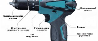
Equipment and hand tools
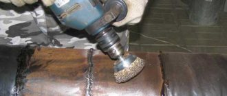
Most of the time during installation construction work, cutting of edges is carried out using grinding machines with abrasive wheels with diameters of 125 and 250 mm. If the thickness of the parts is small, then you can use a file.
Cutting methods
Cutting an edge involves removing part of the metal from the end of the part at an angle. The angle is determined between the plane of the end and the resulting bevel.
Cutting can be done mechanically and thermally. Subsequently, depending on the quality of the formed surface, mechanized or manual finishing is carried out.
Mechanized finishing is carried out on boring equipment for rotating bodies. For straight surfaces, milling machines or pneumatic grinders are used.
If there is no special equipment, then the surface for welding can be modified manually using a chisel and file.
Thermal methods for cutting edges are gas (using oxygen), plasma and laser cutting. When thermal cutting, you can get K-, V-, and X-shaped edge bevels. Mechanical methods include milling, planing, abrasive cutting and slotting devices.
Edges for parts of different thicknesses
There is often a situation where you need to weld parts that differ greatly in thickness. In this case, GOST has special tables, guided by the data from which you can understand how to assemble the connection. If the values from the table do not exceed the permissible values, then the edges are cut as for a thicker part with a smooth transition from a thin part to a thicker one.
It looks something like the picture below.
If the condition is not met, then it is necessary to make a smooth bevel for the thicker part to the thickness of the second (thin) part.
Table for parts of different thicknesses
| For pipelines according to GOST 16037 | |
| Thin wall thickness | Thickness difference |
| Until 3 | 1 |
| More than 3 to 7 | 2 |
| More than 7 to 10 | 3 |
| More than 10 | 4 |
| For metal structures according to GOST 5264 | |
| Thin wall thickness | Thickness difference |
| Up to 4 | 1 |
| More than 4 to 20 | 2 |
| More than 20 to 30 | 3 |
| Over 30 | 4 |
Marking and basting
Upon completion of straightening and cleaning, the second stage of metal preparation before welding begins. These are the so-called “procurement” operations, which involve marking or drafting parts.
The first of them consists of transferring the contours of the workpiece to a prefabricated product, followed by punching the metal along the entire cutting line, as well as marking it.
Basting is carried out by transferring dimensions taken from a pre-made template made of cardboard, thin metal plate or plywood.
During the transfer process, the contours of the template are outlined with a special scriber, and then a core is applied along the resulting line while simultaneously marking the part.
Metal scissors, hand cutters, or automatic gas-flame mechanisms can be used to cut out welded products of varying thicknesses.
Edge processing methods
Now let's talk about how edges are processed for welding. Processing is a very important stage, because if there is dirt on the edges, various inclusions, as well as lubricants or paint, they will certainly lead to the formation of unacceptable defects.
To avoid this, after they have already been prepared, the edges are re-cleaned, wiped, and also degreased using solvents, degreasers or a water-alcohol solution. In some cases, acids and alkalis are used to degrease edge cleaning.
Editing and bending
Eliminating any irregularities in the metal is a mandatory process when preparing it for welding. It is necessary to eliminate all defects in the material, including curvature. Its editing is carried out using pressure.
Advice! Editing must be carried out for non-ferrous and ferrous metals. They can be hot or cold. Defects in rods, wire, pipes, strips, and steel circles must also be eliminated.
The event is carried out in the following ways:
- by machine method using special correcting devices;
- manually using a hammer, anvil, straight plates of cast iron or steel.
Metal bending is another stage in preparing the material for welding. During the event, the workpiece is bent at the required angle with the required radius. As a result, it takes on the desired shape. The process is carried out using machines or manually. Bending of parts is carried out according to templates, samples or by eye.
Edge cutting technology
The edge cutting technique itself, as a rule, does not cause difficulties in understanding when the process is performed using angle grinders (grinding machines) or a file. The parts are taken and the end is ground down and the required edge angle is created. As a rule, this is followed by dulling of the edges.
If the edges are prepared on a milling machine, the product is fixed at the required angle relative to the cutter, which grinds down the metal in the process, then we require an angle. The result is edges with precisely maintained geometric dimensions.
In cases where the edges are prepared on a lathe (this applies to rotating bodies such as round timber, pipes, etc.), the products are installed in the chuck of the lathe, and the excess metal is ground off with a cutter to the required dimensions, creating the desired angle and bluntness. This method also ensures dimensional accuracy.
Sometimes thermal cutting methods are used to cut edges, such as plasma, gas, air-arc and laser cutting. With the exception of laser, after all of the methods given here, the edges must be machined, as the surface will be uneven. It will have deep channels, as well as sagging and splashes of metal. We will not dwell in detail on the preparation and implementation of the cutting process within the framework of this article.
The technology itself consists in cutting off a layer of metal from the end of the product at a close to a given angle. Thermal methods are usually used when thicknesses are greater than 10 mm.
At smaller thicknesses there is not much point in using them, since eliminating defects obtained during the cutting process takes quite a lot of time. And at these thicknesses, this is comparable to the same time that would be spent if the process were performed manually using a grinding machine.
Using manual edge cutters simplifies and speeds up the process of obtaining the desired angle. This device is installed on the end of the product, it is connected and the metal is removed. The quality of the edges is higher than when using an angle grinder, but lower than when using a milling or lathe.
Such devices speed up the process, especially when the diameters are small and there are a lot of joints. In these cases, it is actually an irreplaceable thing.
Butt joint
A butt connection is a type of connection in which parts are connected to each other at their ends. As mentioned earlier, if the thickness of the part is up to 2.5-3 millimeters, then edge cutting is not performed (unless, of course, there are special requirements for the welded joint).
Gusset
Corner joints (seams) have an angle between the part and the edge of the surface being welded. For them, just as for butt joints, the condition of up to 2.5-3 mm is met; you can not cut the edges, because such a small thickness can be welded just like that. Corner connections (pipes insertions) with a diameter of more than 100 mm must be made with mandatory cutting of the edges. This requirement applies to steam and hot water pipes, as well as petrochemical pipes.
Useful article - How to weld using electrodes correctly
Cutting pipes for welding
In this section we will talk in more depth about cutting the edges of the pipe. Welding of pipelines accounts for more than 60% of all welding work, therefore pipe cutting is an extremely pressing issue.
When preparing pipe joints, the following connections are used:
- Angular
- Overlapping
- Butt
Angular - used when welding a pipe with a pipe, a pipe with an insert (fitting and boss), as well as a pipe with a flange.
Lap - used to connect a pipe to a sheet (plug) or welding flat flanges. As such, edge cutting is not performed in this case. The end of the part to be welded and the welding area are simply prepared and cleaned.
Butt welding - used for welding pipe to pipe, to an outlet, to a tee, collar flanges, to shut-off valves, and so on. This is the main type of connection when welding pipelines.
When welding pipelines, the most common is the C17 butt joint with one-sided groove without the use of backing rings. Almost 80% of pipelines are welded with this type of connection. The second most popular are connections C18 and C19 with a remaining or removable backing ring. The bevel angle of the edges for all these types of joints is 30 degrees, with a tolerance of ± 3.
Pipelines with a wall thickness of 2 to 3 (sometimes up to 5 mm) are welded without cutting edges according to connection C2. With this connection, the ends of the parts are simply cleaned to a metallic shine and degreased, and then the joint is assembled, tacked, and welding is performed.
As a rule, of course, starting from a part thickness of 3 millimeters, the edges are cut to ensure penetration and prevent defects at the root of the seam.
Before starting to cut the edges, a very important condition is the perpendicularity of the ends of the pipe.
The deviation from perpendicularity should not be more than one millimeter, otherwise there will be a very large gap in the joint, which, even if it can be welded, will still be a defect since there will be multiple defects in the seam.
Another very important condition is the straightness of the already assembled joint. There should be no fracture at the junction exceeding 1.5 millimeters. This is checked by applying a 400 mm long ruler in 3 different planes.
For bends and tees
It is difficult to imagine a long pipeline without a branch. An elbow is a curved piece of pipe. Bends are made from flexible pipes (sometimes bends are made from pieces of metal - sectors that are welded together). In most cases, bends are welded to the pipe using a butt joint. The cutting of edges is usually performed at an angle of 30±3 degrees (the angle between the axis perpendicular to the axis of the pipe) since the C17 connection method is most often used.
Useful article - What kind of silumin alloy is this?
For fittings and bosses
Fittings and bosses are used to extract part of the medium from a pipeline or to insert various sensors. The fittings are made from pipes, and their length is usually not large, from several tens to several hundred millimeters.
Fittings and bosses are characterized by one-sided cutting of edges of 50±5 degrees, or without cutting of edges at all in cases where this is allowed by the design. If the thickness of the fitting is more than 3 mm and the edges are not prepared, then such a connection will have a structural lack of fusion. The cutting used is U17, U18, and in the case when the edge is cut then U19, U20, U21.
For vessels and tanks
For welding vessels and tanks operating under pressure, there are regulatory documents that tell you how to perform welding work and what is normal and what is defective. But if we are talking about cutting edges, then GOST 5264 still helps us.
Do you know what TIG welding is? If you want to find out, follow the link to our article.
Most often, a one-sided V-shaped cut is used where the thickness is not large (up to 12-15 mm) and there is no possibility of welding on the reverse side. If the thickness is more than 15 millimeters, then it is U-shaped. If it is possible to reach from both sides and the thickness is more than 8 millimeters on both sides, then an X-shaped one is used.
For I-beam
During manufacturing, I-beams or I-beams are welded using a T-joint, and during installation they are connected to each other using butt welds. Here everything is still decided by GOST, according to which the choice of cutting is made.
To weld the upper and lower flanges and the I-beam stand, a cutting with a bevel angle of 45 degrees is used with a permissible deviation of ±2 degrees (connections T8 and T9). Beams can also be welded without cutting the edges, but only when structural lack of penetration is allowed. This is determined by designers at the design stage and supported by calculations.
Cutting cracks in metal
If a crack(s) appears in the metal and needs to be repaired, this is done in several stages. The first thing you need to do is make a sample - select the crack itself and the metal around it. The shape of the sample should resemble the shape of a bowl, with smooth transitions to “healthy” metal and an inclination of the walls from 25 to 60 degrees.
If the crack is through, then it needs to be drilled with a drill with a diameter of 3–5 mm. A plate 2–3 mm thick is installed on the crack, which exceeds the length of the crack by 5–8 millimeters. After which it is tacked at several points (usually 5–6).
For elements of different thicknesses
butt joint with flange (for thin metal)
Different structures and elements have different wall thicknesses:
- when working with thin-walled products (up to 5 mm), cutting edges is not required;
- the presence of edge flanging also does not require cutting them;
- if the wall thickness of the parts is from 5 to 20 mm. It is recommended to carry out a one-sided bevel;
- with product thicknesses from 20 to 60 mm. two-sided cutting should be done.
These rules are standard for different parts and for different types of connections.
#10
Sent 14 February 2022 - 12:35
For what? After all, on the flange of the angle there is already a ready-made edge for welding (radius) and on the channel it’s the same... I roughly imagined how you want to weld it.. But it would be better if they showed the assembly. If the edge for welding is standard, then choose from the GOST 5264 table. And if it is not standard, then the designer must show all dimensions (gap, bluntness, chamfer..)
ingenerkons and Chertil like this
Sincerely
Olzhas
One is groping through the dark labyrinth - maybe he will stumble upon something useful, or maybe he will break his forehead. Another will take at least a small flashlight and shine it in the dark. And as he walks, his lantern glows brighter and brighter, finally turning into an electric sun, which illuminates everything around him and explains everything. So I ask you, where is your lantern! (D.I. Mendeleev.)
#11
Sent 14 February 2022 - 20:45
What’s strange is that there is a procurement shop, where they cut it to size with an allowance and take it to sections.
In addition, technologists often skip such details without a drawing, and it turns out that the work is done, but there is no paperwork to pay for.
#12
Sent 17 February 2022 - 00:04
and why did such a question arise? The technologist cannot decide on standard seams according to GOST??? and why are you worried about the technologist, who is supposedly supposed to be helped by the designer, is this what you decided among yourselves???
Whether he should lay the edges for welding or not is a question for the designer, his boss and the chief. engineer, not yours, he doesn’t discuss whether you owe him anything together with the technologist
And what GOST regulates for welding should be known by the technologist and your master...
if you said a non-standard seam, what to do, and without looking at GOST, immediately saying that someone must do something is somewhat fleeting
(I would answer if you can’t weld the butt joint properly, I’ll lay down the edges with weld root welding, and also on the lining, and I’ll also give an x-ray 100%, so that’s my right, we decided so, so I’ll show off my mind)) just for fun )
#13
Sent 17 February 2022 - 20:16
And such questions arise when one boss wants to push more work onto a neighboring department, we now almost have this as a rule at the enterprise, we need edges, which means there will be a drawing.
Edge surface quality control
The inspection of the surface of the edges is primarily carried out by the welder himself, visually inspecting for defects, and also measuring the bevel angle and bluntness. Next, the edges are checked by a level II–III welding specialist (this is a welding master or engineer). This is a standard control scheme at enterprises. If non-destructive testing is required, the inspection is also carried out by a flaw detector.
When carrying out control, the following is checked:
- Distance of stripped metal from cutting.
- Edge bevel angle and bluntness dimensions.
- Are there any unacceptable defects on the surface (metal peeling, cracks and rough nicks).
- If the part being welded is critical, in some cases non-destructive testing of edges is used (ultrasonic, magnetic or PVC)