The nuances of cutting edges
Cutting for welding has its own characteristics. When cutting, the width of the weld increases. This leads to additional consumption of materials. In some situations, there is no edge preparation, and welding is performed without this preparatory stage. If thin parts are welded, then flanging is used.
Beading is the bending of the edges of the parts being connected. Flanging is carried out manually or by machine. It can be done manually on an anvil using a hammer or sledgehammer. Mechanical processing can also be carried out by planing, milling, chiselling, and the use of abrasives, which requires appropriate equipment, for example, planing or milling machines.
The design of planing machines is quite simple. A high-strength cutter, passing along the end at a set angle, removes a layer of metal with each pass. Then the machine mechanism changes its position and the operations are repeated. Milling machines are used when the surface of parts has a curved shape. The chamfer is formed using a cutter that moves along the seam line.
For large structures and pipelines, edge splitters using the chiselling method are used. Abrasive processing is used for small workpieces and for final finishing after planing and milling. You can remove the edge using a gas cutter. For the machine method, a zig machine is used.
Chamfers on the edges are made on one side or both. One-sided bevels on straight parts make the welding process easier. With double-sided bevels, the welder must have access to both sides of the joint.
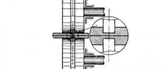
Design parameters
The types of edge preparation for welding differ depending on the selected design parameters:
- Bevel angle . Denoted by the letter "β". This is an acute angle between two planes: the end and the beveled surface. It ranges from 10 to 30 degrees. If only one edge is beveled, then the angle is 45 degrees.
- Cutting angle . Denoted by the letter "α". This term refers to the angle between beveled surfaces. When the bevel angle of both parts is the same, then the cutting angle is equal to its double value. Accordingly, it ranges from 20 to 60 degrees. The correct choice of opening angle ensures that the electrode penetrates deep enough for good welding of the root of the seam.
- Amount of dullness . Denoted by the letter "C". The part of the edge end that remains unbeveled may have a sharp shape. This can interfere with the welding process and cause metal burns in this thin part. To avoid this, they resort to blunting the edges. The size of the bluntness is about 2 mm.
- Gap . Denoted by the letter "b". Is the distance between the edges in the root zone of the weld. A gap is left for better penetration in this area. Its value is usually about 1.5 mm. This value can be reduced or increased depending on the welding process technology.
- Bevel length . Denoted by the letter "L". Adjusts the smoothness of the transition from the minimum size of the beveled part to the thickness of the part. The correct value will eliminate additional stress in this area.
- Height and width are designated as "h" and "b" respectively.
- Seam leg . Denoted by the letter "K". This is the smallest distance from the plane of one part to the border of a triangular seam on another.
Elements of geometric preparation of the shape of edges for welding have their own designation, which is used in the drawings, in technological and design documentation.
Editing the metal sheet
There are two ways to perform straightening: manual - using a sledgehammer or hammer on an anvil, and machine - using special machine tools.
Manual straightening involves the use of a round-faced hammer . Thin sheets and parts made of non-ferrous metals must be leveled using hammers with soft metal inserts. There are metal and wooden smoothers that are used when straightening thin sheet metal.
Machine processing is usually done using straight rollers and presses . When using the correct rollers, the workpiece passes between cylindrical rollers that rotate in different directions, thus aligning the part. When using a press, the workpiece is placed on two supports, after which the convex part of the part is pressed with the press slide. As a result of this effect, the uneven workpiece is straightened.
Types of cuts
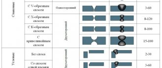
The classification offers various types of edge preparation for welding. They are used depending on the thickness of the elements, the technology used, and the type of seam. Each species is named after the Latin letter it resembles. Three types have a straight bevel, and one has a curved bevel.
V-shaped
It is the most commonly used. This is explained by the ease of implementation and the possibility of use for various thicknesses of welded parts. The thickness range is from 3 to 26 mm.
It consists of cutting both edges on one side. The cutting angle is 60 degrees. Used for butt, corner and T-joints.
X-shaped
It is also used quite often. Bevels are made on both sides. The method is used to connect parts with a thickness from 12 to 60 mm. The cutting angle is the same as in the previous version. There are several passes on each side. With this method, the consumption of electrodes during welding is significantly reduced. Residual deformations during heating are insignificant.
U-shaped
The only type of curved bevel. Sometimes called "skin glass". Cutting edges for welding in this way is the most difficult. The use is justified when it is necessary to obtain a high quality seam. Both edges are beveled equally on one side. Suitable thickness of parts is from 20 to 60 mm. When welding edges in this way, there is a reduced consumption of electrodes. It is difficult to do manually, so edge cutters are used.
K-shaped
The most rarely used method. The bevel of edges for welding in a joint is done only for one part. One of the edges is one-sided, and the second has two bevels at once. If you have any difficulty determining which edge cutting is suitable for welding, the table will help you make the right choice.
It shows that the shape of the edges depends on the type of connection, the nature of the seam and the thickness of the parts being welded.
Metal cutting
To give the workpiece the desired size, mechanical and thermal cutting is used.
Mechanical cutting is carried out using hand or mechanical tools . A band saw, a grinder, and a stationary circular saw are often used.
Thermal cutting is the process of melting metal according to marked marks . To carry out such work, a plasmatron, an oxygen torch, or arc welding are used. This type of cutting is universal, as it allows you to cut workpieces not only in straight lines, but also in curved lines.
Offset parts
The edges do not have to be symmetrical or parallel to each other. However, the displacement of the edges of butt welded joints is limited. All tolerances are specified in regulatory documents. The amount of permissible displacement depends on the thickness of the parts being connected.
Welding pipelines and other various pipes has its own nuances. This will require increased precision. The permissible displacement of the edges when welding pipes will be much less than for parts that have a flat shape. A way to prevent the occurrence of significant displacement is to securely fix the elements being connected. A proven method of fixation is to use tack welds—short transverse seams.
Methods for marking blanks
To obtain parts with the required parameters, it is necessary to cut the profile correctly, and before that it must be marked.
There are three marking methods: manual, optical, measured cutting.
For manual marking, the simplest tools are used, such as a ruler and calipers . When producing small batches of the same type, prepared templates can be used. The significant disadvantages of this method are: low speed and high labor intensity.
In the optical method, markings are applied using special marking machines . These machines have a built-in pneumatic roller that applies markings according to the specified parameters. This method is characterized by high speed.
Measured cutting differs from other methods in that it does not involve profile marking . According to a given program, which specifies the required parameters of the part, the device immediately cuts the workpiece.
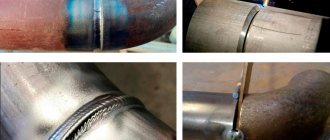
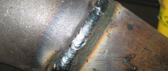
Pipe edges
Pipe connections, in particular pipelines, are subject to increased demands. They are the most difficult to weld and require strength, reliability and durability. The cutting of edges for welding of steel pipelines is determined by the requirements of GOST 16037.
Great importance is attached to the perpendicularity of the pipe axis to its end surface. To meet this requirement, before starting to cut the edges, you should trim the ends and ensure that the required right angle is obtained. The opening angle should be 60-70 degrees. The amount of edge dulling is 2-2.5 mm. Edges for welding pipes can be processed in various ways: using mechanical processing, gas cutting and others.
When assembling the connection, it is necessary to ensure that the axes and joint surfaces coincide. Strict requirements are imposed on the size of the gap. Its value is in the range of 2-3 mm. To avoid misalignment of the connection, the gap must be the same around the entire circumference.
Features of assembling products for welding
The final stage of preparation is the correct assembly of the parts. It is necessary to fix the parts properly so that after the work they remain in the desired position.
Spot welding of parts is often used, since simple fixation is not enough. This welding guarantees the preservation of the structure’s shape and its reliability. This also allows you to conveniently position the workpiece for making a horizontal seam.
Rules for assembling products for welding:
- free access to the place where parts are welded is required , even when using special products for fixation;
- parts must be fixed very firmly and with high precision to avoid deformation during work;
- it is necessary to follow the established sequence of assembly of the structure;
- it is necessary that the structure does not change its position in space.
Common Mistakes
Very often, correction of defects and modification of welding joints is caused by inaccurate preparation of the seam. To get good welding results, avoid these common mistakes:
- Very often you can find beveled edges with an angle that is too sharp, which leads to poor penetration of the weld seam into the depth of the weld joint.
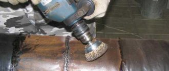
- Not good enough to remove oil, dirt, paint or varnish from the base metal. Improper cleaning methods can cause the grout to become porous. Using grinders is the fastest way to clean the welding area. Make sure you clear at least 2-5cm from the end of the piece to prevent foreign material from getting into the seam.
- Not following welding procedures may seem like a good way to save time and increase productivity, but it can also lead to further rework, corrections, and failed welds. Before welding pipes, you should familiarize yourself with the specifications and technological processes, they usually contain the correct bevel angle, gap size, weld root size and other important details.
Preparation of edges of process pipelines (NGDO4,12, OKHNVP16, MO2, GDO)
Deviation from perpendicularity of the end of the pipe relative to the generatrix: 05 mm. for DN up to 65mm; 1.0mm. for DN over 65mm. up to 125mm; 1.5mm for DN over 125mm. up to 500mm; 2.0 mm for DN over 500 mm (clause 7.1.18. PB 03-585-03)
The edges of pipes (elements) and adjacent areas on the internal and external surfaces are at least 20 mm wide. must be cleaned from rust and dirt to a metallic shine and degreased (clause 7.1.19. PB 03-585-03)
Gas, air-arc or plasma cutting of pipes made of hardening heat-resistant steels must be carried out with preheating at 200-250 C and slow cooling. After cutting, the edges must be checked by penetrant or powder flaw detection. Detected cracks are removed by mechanical cleaning along the entire edge. (clause 7.1.16., 7.1.17 PB 03-585-03)
After thermal cutting, the edges of pipes made of hardening steels must be cleaned to a depth of at least 3 mm, and those of carbon and austenitic steels to a depth of at least 0.5 mm. from the largest depression of the cut (clauses 18.20,18.21 RD 38.13.004)
Preparation of pipeline edges for boiler equipment (KO1,2)
The ends of pipes made of carbon and low-alloy steels can be processed by oxygen, plasma-arc or air-arc cutting, followed by cleaning the edges with a cutting or abrasive tool until traces of fire cutting are removed. The edges prepared for assembly must be free of breaks, burrs, sharp transitions and sharp corners.
The edges and adjacent areas of the surfaces of the parts must be cleaned to a metallic shine and degreased to a width of at least 20 mm along the outer surface. from the cutting edge, at least 10 mm on the inside. When installing the fitting, the surface on the seam side must be cleaned to a width of 15-20 mm. from the hole, and the surface of the glasses to the entire depth. (clause 6.2.4. RD 153-34.1-003)
Oxygen cutting of pipes made of chrome-molybdenum and chrome-vanadium steels with a wall thickness of more than 12 mm. at air temperatures below 0 C, it is necessary to carry out preheating at 200 C and slow cooling. (clause 6.1.5. RD 153-34.1-003)
When thermally cutting high-alloy steels (martensitic, martensitic-ferritic and austenitic classes), an allowance of at least 1 mm must be provided. for subsequent mechanical processing (clause 6.1.4. RD 153-34.1-003)
Preparation of edges of building structures
Immediately before welding, the edges and adjacent areas are 20 mm wide. for manual or mechanized arc welding and at least 50 mm. for automatic, as well as the junction of the initial and output strips must be thoroughly cleaned of scale, dirt, paint, oil, rust, moisture, snow and ice. (clause 5.6. RD 3415.132, clause 1.4.2 OST 36-58, clause 6.5 OST 36-60)
Fire cutting of edges of parts made of steel C345 and more durable at ambient temperatures below minus 15 C should be carried out with preheating of the metal in the cutting zone to 100 C. (clause 5.5. RD 3415.132)
After thermal (oxygen, air-arc, plasma) cutting, the cut surfaces must be mechanically processed:
- on elements made of steels C235 to C285 - until cutting marks are removed
- on elements made of steels C345 to C375 - with removal of a layer with a thickness of at least 1 mm.
- on elements made of steels C390 to C440 - with removal of a layer with a thickness of at least 2 mm.
When processing with an abrasive tool, the stripping marks should be directed along the edges (clause 5.3. RD 34 15.132).
Preparation of edges of pressure vessels (GOST R 52630-2007) (KO 3, OKNVP 1.2)
The form of edge preparation must comply with the requirements of the technical documentation or project.
The edges of vessel elements prepared for welding must be cleaned to a width of at least 20 mm. The edges must be free of traces of rust, scale, oil and other contaminants. Edges must undergo visual inspection to identify metal defects. Delaminations, sunsets, cracks, and for two-layer steel, also peeling of the corrosion-resistant layer are not allowed.
When the thickness of rolled sheets is more than 36 mm, the area adjacent to the edges should additionally be monitored using an ultrasonic method over a width of at least 50 mm to detect cracks, delaminations, etc.