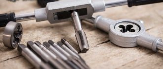
Thread measuring instruments. Thread measuring wires.
One of the more progressive methods of control is active.
It is more correct to use it in the conditions of mass and large-scale production. Active control devices with a certain dimensional measurement allow you to automatically change the course of the technological process and ensure the specified processing accuracy. Active control devices can be turned on at the end of the processing cycle and, based on the measurement results, issue a command for sub-adjustment of the cutting tool (they are called sub-adjusters) or create a check of the dimensions of the product specifically during the processing process in order to regulate the amount of movement, cutting modes and other characteristics of the technological process. Active control devices that regulate the characteristics of technological actions are used in computer-controlled machines.
For automatic control and adjustment, contact and non-contact devices are used. For contact action devices, the tip is in contact with the product being measured and, when triggered, can be a source of device error. To reduce this ability, the tips of active control devices are made of carbide, diamonds, agates or other particularly hard materials.
Devices for measuring threads.
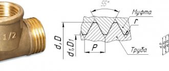
The main controlling parameters of threads are the external middle and internal diameters, profile angle and pitch. When measuring threads, comprehensive and element-by-element inspection tools are used.
For comprehensive control of external metric threads, solid limit ring gauges ( GOST 17763 - 72 and GOST 17764 - 72 ) or threaded clamps are used. Internal threads are checked with thread plug gauges ( GOST 17756 - 72 and GOST 17759 - 72 ). When used with thread plug and ring gauges, the all-encompassing gauge is the bore size. The no-go size is used to measure the maximum size of the average diameter.
With element-by-element inspection, the outer diameter of the bolt can be checked by any measuring instrument used to control the diameter of the shafts, and the internal diameter of the nut by any measuring instrument used to control holes.
To control the average diameter, contact or non-contact methods are used. The contact control method is based on the use of micrometer inserts or three wires.
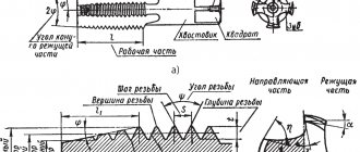
Thread micrometer inserts.
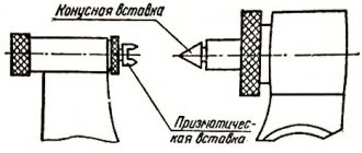
A micrometer with inserts is used to control the average diameter of triangular threads with profile angles of 60 and 55°. The measurement is made in the range from 0 to 350 mm, while for each interval of 25 mm either separate micrometers or special interchangeable anvils are used. The set of inserts for the micrometer consists of two inserts (Fig. 1): a prismatic one, which is installed instead of the heel of the micrometer, and a conical one, installed in the hole of the micrometer screw.
Rice. 1. Inserts for thread micrometer.
The micrometer is equipped with five sets of inserts, which are installed in relation to the pitch of the thread being tested: 0.4 - 0.5; 0.6 - 0.8; 1 - 1.5; 1.75 - 2.5 and 3 - 4.5 mm.
Measuring threads using the three-wire method.
When checking the average diameter, a set of three wires of similar diameter is used. During the measurement process, two wires are installed in the thread recesses on one side, and the third in the opposite recess. The size of the wires is selected according to a special table depending on the pitch and angle of the thread profile. The perfect size for wires is the diameter d = tan α /2c, where cs is the pitch, and α /2 is the profile angle of the thread being tested.
Measurements of the average diameter of the thread.
Depending on the required accuracy when measuring with wires, micrometers or optical-mechanical devices are used, which provide the most clear readings. If the axes of the wires are placed vertically during measurement, then the wires are suspended on a bracket mounted on the device being used (Fig. 2). Measuring surfaces are brought to the wires and the distance between the protruding points of the three wires located in the recesses of the thread is determined, then the average diameter is determined using the formulas.
Calculation of the average diameter of the thread.
Average thread diameter with a profile angle of 60°:
Dcp = M – 3 d + 0.866 s ,
where M is the size acquired as a result of measurement, mm;
d—wire diameter, mm;
s — pitch of the measured thread, mm.
If the profile angle is 55°, then the average diameter of the cylindrical thread:
Dcp = M – 3.165 d + 0.9605 s .
Rice. 2. Measuring the thread using three wires.
Non-contact methods for monitoring threads using the average diameter of the thread are based on three wires, the use of measuring microscopes with goniometric eyepiece heads, and also projectors.
Indicating measuring instruments.
Monitoring the accuracy of the thread pitch and measuring the profile angle is also carried out using measuring microscopes or projectors.
Control of the average diameter of the internal thread can be carried out by indicator devices with sliding half-plugs, indicator devices with sliding inserts, also on horizontal optimeters using measuring arcs for internal measurement equipped with ball measuring tips.
Interesting read: How to solder wires correctly?
At most factories, when boring holes for preparatory measurements, they use plugs and punches, as well as calipers. Setting the cutter to remove chips to the required size is done along the dial of the machine's transverse support based on the readings of the caliper. When machining holes according to the 2nd and 3rd accuracy classes, this accepted measurement method is associated with a greater amount of time spent on removing test chips, and often on extra passes.
You can measure the dimensions of a number of parts during processing using an indicator device (Fig. 3), which, thanks to the special design of the stubborn bar 1, allows you to install the indicator holder 3 4 in a comfortable place, in front of the transverse slide of the caliper. When feeding the transverse slide away from you, the indicator pin rests against the protrusion of bar 1. Screw 2 protects the indicator from breakage. This device is universally suitable; it can be used both for boring and turning. For turning, the stubborn bar and indicator 3 are rotated 180°.
Rice. 3. Indicating device for active control of dimensions during machining on a lathe.
Practice has shown that the use of indicators and setting rings with the nominal size of the hole being machined, as well as the use of an indicator device (Fig. 3), can reduce auxiliary time and ensure the highest accuracy of measurements of internal dimensions.
When processing holes, you need to use the indicator to adjust the cutter to remove the first chip with an allowance of 0.1 - 0.2 mm per side, see the indicator reading and remove the first chip. After this, measure the acquired hole size with an indicator device adjusted to the setting ring that has the nominal hole size (when adjusting, the indicator device is set to zero).
Having measured the hole, it is determined which layer of alloy needs to be removed with a cutter to obtain the final size of the hole, and using the indicator, the cutter for boring the hole is set to the finishing size. This measurement method simplifies boring holes according to the 2nd and 3rd accuracy classes, and it is completely accessible to unskilled workers.
With large batches of small parts, from time to time it is deliberate to first carry out preparatory boring of the entire batch of parts with an allowance of 0.3 - 0.5 mm per diameter and then, in one pass, using a hard cutter, carry out finishing boring.
Taking into account that the cutter wears out during operation, as a result of which the size of the hole is miniaturized, during the processing of each subsequent part, you should inspect the actual size of the hole of the already processed part with an indicator for internal measurements and, based on the indicator readings, adjust the indicator device taking into account the wear of the cutter.
The advantage of working with an indicator is that its readings are not affected by wear on the threads of the screw and the nut of the transverse caliper, whereas the readings on the dial depend on the degree of thread wear.
It must be emphasized that the accepted methods of boring holes do not provide the highest accuracy. When processing a hole whose diameter is smaller than this, the turner does not have a clear idea of how many hundredths of a millimeter must be additionally removed to obtain the final size. Therefore, he is often forced to resort to additional passes, which significantly increases the processing time and worsens the quality.
The use of indicator devices makes it possible to work confidently and with greater accuracy. The introduction of an indicator does not exclude the introduction of limit calibers. Checking the holes with the limit gauge is indispensable during the final size control.
TECHNICAL REQUIREMENTS
2.1. Wires and rollers should be manufactured in accordance with the requirements of this standard according to drawings approved in the prescribed manner, dimensions:
| from 0.045 to 0.346 mm for type I, |
| » 0.115 » 4.980 mm » » II, |
| » 5.176 » 35.00 mm » » III. |
2.2. The design of the wires must ensure the possibility of their use with devices for hanging or installation on the device.
Note. The device for hanging wires on the device must have a hanging hole with a diameter of at least 2.5 mm and provide a distance from the center of this hole to the middle of the wire length of at least 55 mm.
2.3. Wires and rollers should be made of carbon steel U10A, U12A in accordance with GOST 1435; made of chromium steel X - according to GOST 5950; made of bearing steel ШХ15 - according to GOST 801.
It is allowed to make wires and rollers from high-speed steel.
2.4. The working surfaces of wires and rollers with mm must have chrome or other wear-resistant coating.
2.5. Non-working surfaces of wires and rollers without a wear-resistant coating must be subjected to anti-corrosion treatment.
2.6. The hardness of the working surfaces of wires and rollers made of carbon and chromium steel is not lower than 58 HRC; from high-speed steel - not lower than 62.1 HRC.
Type I wires can be produced with a hardness of at least 49.7 HRC.
2.7. Wires and rollers for measuring the average diameter of external threads should be made of two accuracy classes: 0 and 1. Wires and rollers for measuring the parameters of spline involute connections - accuracy class 1.
2.8. The roughness parameter according to GOST 2789 of the working surfaces of wires and rollers is no more than 0.04 microns.
2.9. There should be no defects on the working surfaces of the wires and rollers that impair their performance.
2.10. Wires and rollers should be produced in sets consisting of:
of 3 pcs. one type with equal nominal diameters - for measuring the average diameter of external threads;
of 2 pcs. of the same type with equal nominal diameters - for measuring the parameters of spline joints.
2.11. The symbol for wires and rollers must consist of the name (“wires”, “rollers”) of the type, nominal diameter, accuracy class and designation of this standard.
An example of a symbol for smooth wires with a diameter of =0.101 mm, accuracy class 0:
Wires I-0.101 class 0
GOST 2475-88
An example of a symbol for stepped wires with a diameter of = 2.095 mm, accuracy class 1:
Wires II-2,095 class I
GOST 2475-88
An example of a symbol for rollers = 5.207 mm, accuracy class 0:
Rollers III-5,207 class 0
GOST 2475-88
2.12. Wires and rollers should be subjected to aging and demagnetization.
2.13. The full installed life of wires and rollers is at least 2000 measurements.
The limit state criterion is non-compliance with the requirements of clause 1.8.
Methods and instruments for monitoring thread characteristics
Thread control is a set of procedures for measuring the main features of a cut. To properly measure the characteristics of a thread, it is worth finding the right methods and means of control. When monitoring the main characteristics of cutting, three-wire methods are often used; the means of control are measuring devices with indicators and micrometers. There are 2 main methods of thread control:
- Method of differentiation: any component is measured separately.
- Comprehensive testing method: all characteristics are checked together using scale-free instruments.
To control pipe and cone threads, gauges are often used to measure the dimensions, shape and relative position of the surface of the part.
Specifications
| Characteristic name | Meaning |
| Roughness parameter Ra according to GOST 2789-93 of working surfaces of wires and rollers, microns, no more | 0,04 |
| Terms of Use: - normal temperature range, °C for: roller wires — relative air humidity, %, no more | From +15 to +25 From +17 to +23 80 |
| Full installed life of wires and rollers, measurements, not less | 2000 |
Disadvantages of threaded connections
When inspecting threaded surfaces, the following defects in threaded connections can be identified:
- Torn tenderloin. This disadvantage occurs when the diameters of the hole and the rod differ from the nominal diameter. Also, the basis may be the unsatisfactory sharpness of the cutting tool. To prevent difficulties, you should carefully check the values of all diameters and replace the dull tool with a sharpened one.
- Dumb cut. Such a disadvantage appears if the nominal diameter is smaller than the diameter of the hole, but larger than the diameter of the rod. Eventually, when cutting, the profile becomes incomplete. To avoid a similar drawback, you need to take clear measurements of the diameters before cutting.
- Thread taper. The basis for the appearance of this defect is the incorrect size of the cutting object, the teeth of which cut off excess alloy. The only solution to this difficulty is to correlate the established dimensions of the part and the cutting device.
- Tight cut. If the dimensions of the part and the roughness of the tool thread are not observed, the cutting process takes place with great difficulty. This shortcoming is prevented by correctly measuring the characteristics of the workpiece and determining the clear dimensions of the cutting tool.
Interesting read: Why doesn't tin stick to the wire?
To control thread defects, gauges are used. They are divided into the following varieties:
- Location size. This type of gauge is created according to the average permissible dimensions of the part under control. The check is carried out by inserting the location gauge into the workpiece. If the cutting is done properly, then the entry should be made with more or less density, slowly and smoothly.
- Calibers with limits. This type of caliber is made in accordance with the maximum dimensions of the initial workpiece. It is divided into 2 sides. One of them corresponds to the largest size of the part, the other – to a very small one. One side must not go into the hole being measured so that the specialist can find the true dimensions of the part.
- Control calibers. This type of gauge is intended to check the characteristics of holes directly during the work process.
- Receiving gauges. These calibers are special instruments that are the primary working devices for employees of the technical control department (QCD), who do their work at inspection points.
Thread control devices
To calculate the characteristics of the metric variety of threads using a comprehensive inspection method, gauges in the form of rings and staples are used. Measurements are carried out in accordance with GOST 17763. Internal threading is controlled by plug gauges. Control of a cut with a profile angle of 55° is carried out using a micrometer with special inserts. 5 sets of inserts are placed on the measuring device; their size is set by the thread pitch. There are 2 main types of inserts:
- prismatic: placed on the heel space of the micrometer;
- conical: placed in the hole of the micrometer screw.
To control the angle of the thread profile, QD workers use devices with hidden indicators: microscopes and projectors. They are equipped with sliding inserts and ball-shaped tips. The system of devices with indicators consists of a stubborn rail, a holder and indicators. The fundamental advantage of indicator devices is their versatility. With their help, you can carry out measuring work both during boring and when turning a part. They provide enormous measurement accuracy in a short period of time.
There are additional devices with indicators for monitoring the taper of the part. They are made according to the Western API standard and form the size of threaded connections in the range from 1.5 to 24 inches. The design of these devices is demonstrated with removable measuring tips. They transmit measurement results to a separate indicator, which displays the data received on the screen. A master who uses indicator instruments to determine the taper of a part will not need approximate templates for control. This characteristic is caused by the fact that the device tips are constantly trying to present the highest aspects for the indicator at the smallest distance of 1 inch.
When checking threads, factory employees use calipers and weights to measure linear units of measurement. They help you find the cutter size that will remove the appropriate amount of chips from the workpiece. These measuring instruments make it possible to save time when machining holes of medium and high precision.
Thread pitch measurement
To control similar properties, such as thread pitch, ordinary rulers with millimeter and inch divisions, as well as thread gauges, are used. The results of pitch calculations using a ruler are inaccurate and are performed by measuring a certain number of turns. The main task of measurement is to find the number of turns that fall on a single thread pitch. In the conventional case, when there are 5 turns per 1 inch, the pitch is equal to 1/5 inch. For convenience, the acquired results in inches are converted to millimeters. During the process of measuring turns using a ruler, a person must keep in mind the following characteristics:
- To achieve the greatest accuracy, you need to measure not just certain sections, but the entire part of the part profile.
- Before the measurement procedure itself, it is necessary to calculate the whole number of turns.
- The thread pitch is set after measuring the depth and main characteristics of the threaded connections.
As a result of the measurements, the average step value is found. The calculation error depends on the correctness of the part cut.
A thread gauge can provide clearer pitch measurements for pipe tapered threads because it can handle very tight spacing.
Its design includes plates made of iron alloys. Any plate is equipped with cutouts equivalent to the profile of the cutout and its pitch. To determine the pitch size, the thread gauge is applied to the part being measured. The thread gauge plate makes a clear control only when it is parallel to the axis of the cutting. It is important that the plate and the thread hole match in size.
Interesting read: How to properly solder a wire to a board?
ACCEPTANCE
3.1. To check the compliance of wires and rollers with the requirements of this standard, state tests, acceptance inspection, periodic tests and reliability tests are carried out.
3.2. The procedure for conducting state tests is in accordance with GOST 8.383* and GOST 8.001*. _______________ * PR 50.2.009-94 is in force on the territory of the Russian Federation.
3.3. When carrying out acceptance inspection, each wire or roller should be checked for compliance with the requirements of paragraphs 1.8 and 2.9.
Check according to paragraph 1.8 (regarding the error in the shape of the working surface of wires with a nominal diameter of up to 0.346 mm), 2.2; 2.6; 2.8; 2.10; 2.12 (regarding demagnetization), 5.1; 5.4 should be carried out selectively according to GOST 18242 and GOST 18321.
Sampling plan:
control level - II;
type of control - normal;
type of control plan - single-stage;
sample size from the batch - according to GOST 18242*;
the method of selection from the batch is “blind” according to GOST 18321;
acceptance level of defects - =0.65. _______________ * GOST R 50779.71-99 is in force on the territory of the Russian Federation.
The batch meets the established requirements if the number of defects in the sample is less than or equal to the acceptance number and does not meet the established requirements if it is equal to or greater than the rejection number for a given inspection plan.
3.4. Periodic tests are carried out at least once every three years for compliance with the requirements of paragraph 1.1; 1.7; 1.8; 2.2; 2.4; 2.5; 2.6; 2.8; 2.9; 2.10; 2.12.
For testing, at least 10 sets of wires and rollers are selected from those that have passed acceptance control, including at least two nominal diameters of the 0th and 1st accuracy classes.
If during periodic testing it is discovered that the wires or rollers do not comply with at least one requirement of this standard, then twice the number of wires or rollers of a given size are tested.
The results of repeated tests are final.
3.5. Compliance with the requirement of clause 2.13 is confirmed by the results of an analysis of the controlled operation of at least 10 sets of wires or rollers, which can be combined with periodic tests.
Measuring the average thread diameter
The average diameter of the cut is checked with a micrometer. The main components of this tool are replaceable tips that are placed in the screw hole. This measuring device provides clearer thread measurements.
If only average values of the thread diameter are needed for work, then you can use a special device - calipers. Its device is demonstrated by ball tips, the dimensions of which must match the type and pitch of threaded connections. The tips of the calipers are placed according to the thread gauge, giving the average diameter size. Then it is necessary to create similar actions with the sides of the part. To control the acquired results, threaded staples are used. The accuracy of the diameter is assessed by comparing the resulting thread with the initial template.
If it is necessary to create control of the average diameter of a short length, consisting of a maximum of 2 turns, then the craftsmen use a method in which 2 wires are used. This option for measuring threads is distinguished by the fact that wires are placed on the reverse projections and valleys of the thread, the diameter of which is considered a tabular unit. The distance between the ends of the wires indicates the number of the average diameter of the part. For any accuracy class, certain wires are produced, created in accordance with GOST 2475-88. When determining the final numbers, it is very important to be aware of the permissible errors, because 2 wires do not make it possible to obtain very clear values.
Also, this thread parameter can be measured using a microscope. The device is applied to the sides of the workpiece profile. The microscope eyepieces are aimed at the profile image from all sides to determine its size. The acquired values are added up and divided by the number of sides. The resulting arithmetic average is considered the real value of the average diameter of threaded connections.
For production work, it may be necessary to additionally control the average diameter of the shaft. They contain bearings, couplings, flanges and gears, thanks to which the part rotates. Its diameter is calculated during the torsion process. The final value is found by the formula d=(T/0.2[t]) 1/3. Extraneous factors (hole size and side height) can affect the final result.
LABELING, PACKAGING, TRANSPORTATION AND STORAGE
5.1. The following must be applied to devices for hanging or installing wires and to non-working surfaces of rollers:
nominal diameter;
accuracy class for products of accuracy class 0;
manufacturer's trademark;
release date designation;
image of the state Quality Mark when it is assigned in the manner established by the USSR State Standard.
Notes:
1. For Type I wires, markings should be applied only to the case.
2. It is allowed to apply the image of the state Quality Mark only in the operational documentation.
5.2. Before packaging, wires and rollers must undergo preservation in accordance with GOST 9.014.
The conservation period is at least 2 years.
5.3. Wires and rollers wrapped in capacitor paper in accordance with GOST 1908 must be placed in sets in cases to ensure their safety.
Note. Wires measuring up to 0.118 mm are packed in four sets in one case.
5.4. Each case must be marked with:
nominal diameter;
accuracy class;
manufacturer's trademark;
designation of this standard.
5.5. For transportation, a batch of wires (rollers) packed in cases must be placed in boxes in accordance with GOST 2991, lined inside with waterproof material.
It is allowed to use other boxes for transportation that ensure the safety of the wires (rollers) during transportation and are made according to drawings approved in the prescribed manner.
5.6. Each batch must be accompanied by a document certifying the compliance of the wires (rollers) with the requirements of this standard.
5.7. Transport marking - according to GOST 14192.
5.8. Wires and rollers in packaging according to clause 5.5 are transported by all types of transport in covered vehicles or containers in accordance with GOST 13762.
5.9. Packed wires and rollers should be stored in a dry room under conditions according to group 1 (L) of GOST 15150.
Measuring the outer thread diameter
Control of the outer diameter of the thread is carried out when using micrometric tools, the design basis of which is microscrews. The calculation occurs in accordance with the following method:
- Microscrews are applied to the thread profile. To adjust the position of the tool, it is necessary to make several rotations of the micrometer.
- Record the cutout profile size for one side. The value is calculated based on the division value on the microscrew scale.
- Place a micrometer on the back end of the profile and find its size.
- Find the outer diameter of the cut by subtracting the value of the second calculation from the result of the initial calculation.
Measuring the diameter inside the thread
The diameter inside the notch is controlled by a measuring device with pointed legs - calipers. To organize computational work, you need to install the tool on a template part using a thread gauge, and later create a comparison with the initial internal diameter of the threaded connections. The caliper must be at an angle relative to the axis being measured.
Also, measuring internal threads can be done with devices for cylindrical threads. This is due to the fact that the inside diameter has a flawless surface, which is perfect for the shape of the tips used in these instruments. The purchased measurements are checked using plug gauges.
Completeness
Table 7 — Completeness of measuring instruments
| Name | Designation | Quantity |
| Wires or rollers: | — | |
| - with equal nominal diameters for measuring the average thread diameter | 3 pcs. | |
| — with equal nominal diameters for measuring the parameters of spline connections | 2 pcs. | |
| Case | — | 1 PC. |
| Passport | PR.01.001.PS | 1 copy |
Measuring threads using the three-wire method
The three-wire method is mainly used to control the average diameter of the thread. The designation of diameter values occurs by placing wires of the 1st and the same diameter on the cavities of threaded connections. The size of the structure that came out is measured with a micrometer. The profile error can greatly help the final result of calculations. To eliminate this incorrectness for us, it is necessary to place wires on the profile so that they are connected at the level where the width of the depressions is equivalent to the width of the protrusions. The wires should lie like this: 1 wire is located on the depression on the left side, and the other 2 wires are located on the depressions on the other side. It is important that during measurements the part was not deformed and the wires were not bent
In addition, the area of use of the three-wire method is considered to be control of the diameter of trapezoidal threads. Only in this version, the part is checked using three specialized rollers.
If you find an error, please select a fragment of text and press Ctrl+Enter.
APPENDIX 1 Recommended
SELECTION OF WIRES AND ROLLERS FOR MEASUREMENT OF THE AVERAGE DIAMETER OF EXTERNAL THREADS
1. Terms and explanations
1.1. - the nominal diameter of the wire or roller, which, in the process of measuring a thread with a symmetrical profile, provides points of contact with the measured profile at the level of the average diameter (Fig. 4).
Damn.4
For a thread with an asymmetrical profile, the point of contact of a wire of nominal diameter with the profile being measured is provided only on the side of the cavity with a large angle of inclination (Fig. 5).
Damn.5
1.2. ; - limiting values of the diameter of the wire or roller, at which the points of contact with the sides of the thread profile are removed from the points of contact (provided by wires with a diameter of ) at the maximum permissible distance (Fig. 6 and 7).
Damn.6
Damn.7
2. When using wires and rollers of the preferred diameter, the measurement error is minimal.
3. When using wires and rollers of preferred diameters to measure the average diameter of threads with an asymmetrical profile, the error of the largest angle does not affect the measurement result, but the error of the smallest angle affects the measurement result and must be taken into account.
4. The use of wires and rollers with a preferred diameter is not allowed if:
the point on the wire or roller with a diameter that is farthest from the thread axis is located below the outer diameter of the thread;
In trapezoidal threads, the diameter of the wire or roller touches the internal diameter of the thread.
In the above cases, wires with a diameter of more than .
If wires or rollers of preferred diameters are not available or cannot be used, then for each specific measurement case the sizes of wires and rollers can be selected from those given in Appendix 2.
In this case, the selected diameter of the wire or roller must be equal to or less and greater, and the measurement results must be corrected.