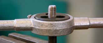
Cutting - tapered thread
Cutting a conical thread on a screw-cutting lathe is done using a copy ruler, which is set to a cone angle of 9 - The thread pitch is set in the same way as for cylindrical threads.
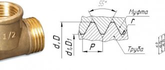
[1] Taper thread cutting is carried out on machines with a tapered ruler. The bisector of the conical thread profile, according to the standards adopted in the USSR, is perpendicular to the thread axis. The pitch is measured in a direction parallel to the thread axis. The average diameter of a tapered thread in each section perpendicular to the axis has a different value, therefore, on a tapered thread, the measurement plane is set at a distance a from the end. In the measurement plane, the values of the outer, middle and inner diameters of the thread are indicated. [2]
Taper thread cutting is carried out on machines with a tapered ruler. The bisector of the conical thread profile, according to the standards adopted in the USSR, is perpendicular to the thread axis. [4]
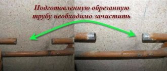
It is unacceptable to cut a tapered thread from the side of the untreated surface due to possible size fluctuations from this surface to the measuring base. Therefore, before cutting a tapered thread, the raw surface should be counterseen. [6]
Conical and self-opening taps are used to cut conical threads. [7]
To cut conical threads, heads with large combs are used, designed for cutting cylindrical threads. [8]
Round cutters are usually used to cut conical threads. Rod incisors are used very rarely; but their designs are almost no different from rod cutters for cylindrical threads. [9]
For cutting conical threads with a taper K - y - - it is advisable to use dies with an uneven cutting offset. [10]
To cut conical threads on pipes, pipe cutting chucks are used, installed on special machines. During threading, the chucks rotate, but the pipe does not rotate. [eleven]
Dies of a special configuration are used for cutting conical threads. [12]
To cut conical threads, dies with conical threads are used. [13]
To cut conical threads with a taper k - j, it is advisable to use dies with an uneven cutting offset. [14]
A diagram of cutting conical threads with taps is shown in Fig. In some cases, this scheme is also used for cutting cylindrical threads. [15]
Threaded connections are the most reliable of detachable connections. They were first used in antiquity, and have been significantly improved since then. Before the invention of the screw-cutting lathe in the 17th century, each bolt-nut pair was made individually; they were not interchangeable. In the 19th century, during the development of railways in England, inventor Sir Joseph Whitworth proposed and introduced a threading standard that has since bear his name. For cutting external threads, a screw-cutting lathe or special dies are used; for cutting internal threads, taps, a type of milling cutter, are used.
GOST requirements
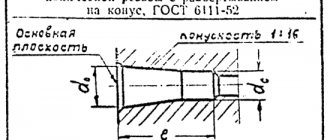
Basic requirements of GOST 6111-52:
- the deviation of the axis of the base plane to the nominal diameter should not exceed the thread pitch;
- the position of the base plane is specified by the distance from the end of the workpiece;
- the diameters of the tapered thread are located in a single main plane and are determined by the design section;
- the length of the external thread l2 is determined based on checking the average diameter with a corresponding ring gauge, and the external thread - with a plug;
- when screwing on pipes and couplings of nominal sizes, the plane of the thread must coincide with the end part of the coupling;
- the number of turns on the large diameter of the cone should not be less than two;
- the length from the base plane to the end of the tube can be reduced, but still meet other requirements of the standard;
- the generatrices of the cone with the center line should make an angle of 1047'24”.
Conical thread according to GOST (Photo: Instagram / metall_detal)
Requirements GOST 6211-81
The values of the average d2 and internal d1 diameters must be calculated using the formulas:
d2=d-0.640327•P;
d1=d-1.280654•P;
where d is the outer diameter;
P - step.
- the length of the internal thread should be 0.8(l1-Δ1l2), where Δ1l2 are the values indicated in Table 2, GOST 6211-81;
- the distance of screwing the external thread onto the internal thread should be l1+Δ1l2;
- the displacement of the base plane is a total value determined by the pitch, the angle of inclination of the profile, the angle of the cone, the average diameter;
- Tolerances for the average diameter are indicated in Table 3, GOST 6211-81.
Design features
At first, the internal thread was cut using simple devices in the form of a tetrahedral rod sharpened to a cone. At the conical end, cutting teeth were cut out, which, when screwing the rod into the hole, scratched a thread into it. Further improvements resulted in the tap having a positive rake angle, chip ejection flutes, and a better fit of the cutting edges to the thread profile.
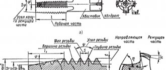
A modern tap contains the following mandatory structural elements:
- The head (or intake) part is in the shape of a gentle cone, which serves to begin the formation of the thread profile.
- A certain number (2-6) of lateral grooves that provide chip removal and lubricant (coolant) flow.
- The calibrating part, in the form of an extended cylinder, completes the precise formation of the profile.
- A shank used to secure the tap in the chuck or collar clamping device.
In cross section, the shape of the groove is determined by its two surfaces: the front edge of the cutting tooth of the tap and the back of this tooth.
The following types of chip flutes are distinguished:
- Single-radius - the cross-section is an arc of a circle, used on calibration tools.
- Straight - U-shaped cross-section, used for cutting nut threads.
- Mixed - straight front and arched back. This is how most universal tools are made.
Types of tap grooves
In addition, the grooves are divided into:
- Straightforward. Used in a universal tool.
- Left spiral. Left-handed ones are used for cutting threads for passage. The chips are pushed into the space in front of the tap, thus protecting the already formed profile from damage.
- Right spiral. Right-handed taps are used for cutting blind holes; with such grooves, chips are pushed out and do not clog the hole.
The conical shape of the head makes it easier to center the tap in the hole and start cutting the first threads of the thread. The angle of inclination of the cone varies between 3° and 20°, the specific value is determined based on the purpose of the tool - roughing, intermediate or finishing pass.
The cylindrical part is actually an inverse cone with a very small taper angle. The underestimation reaches 0.1 mm, this helps reduce friction during cutting.
Adaptations
Manual or automatic cutting methods provide results in various classes of accuracy and roughness. Thus, the main tool remains a tap, which is a rod with cutting edges.
- manual, for metric (M1-M68), inch - ¼-2 ʺ, pipe - 1/8-2 ʺ;
- machine-manual - attachments for drilling and other machines, used for the same sizes as manual ones;
- nuts, which allow you to cut a through version for thin parts, with nominal sizes of 2-33 mm.
- For cutting metric threads, use a set of rods - taps:
- rough, having an elongated intake part, consisting of 6-8 turns, and marked with one mark at the base of the shank;
- medium - with a fence of average length of 3.5-5 turns, and markings in the form of two marks;
- the finishing part has a fence of only 2-3 turns, without marks.
Tolerance control of metric thread placement
When cutting manually, if the pitch exceeds 3 mm, then use 3 taps. If the product pitch is less than 3 mm, two are enough: roughing and finishing.
Taps used for small metric threads (M1-M6) have 3 grooves that carry chips and a reinforced shank. The design of the others has 4 grooves, and the shank is through.
The diameters of all three rods for metric threads increase from rough to finish. The last threaded rod must have a diameter equal to its nominal diameter.
The taps are attached to special devices - a tool holder (if it is small) or a crank. They are used to screw the cutting rod into the hole.
Preparing holes for cutting is carried out using drills, countersinks and lathes. It is formed by drilling, and by countersinking and boring it is increased in width and improves the quality of the surface. The fixtures are used for cylindrical and conical shapes.
A drill is a metal rod consisting of a cylindrical shank and a helical cutting edge. Their main geometric parameters include:
- the helical lift angle is usually 27°;
- point angle, which can be 118° or 135°.
Drills are rolled, dark blued, and shiny - ground.
Countersinks for cylindrical shapes are called counterbores. They are metal rods with two cutters twisted into a spiral and a fixed guide pin to insert the countersink into the cavity.
Types by purpose
According to their purpose, the following types of taps are distinguished:
- Locksmiths. Designed for manual use, they have a square shank. They are supplied complete with a crank, which ensures rotation of the tool and cutting threads. They are used as part of a set of two or three taps, slightly different in diameter. Each person removes their own part of the allowance from the surface of the hole. Inside the set, tools are distinguished by the number of lines engraved or stamped on the shank; the roughest, rough one has one line, the intermediate one has two and the finishing one has three.
- Machine or machine-manual. With such taps, cutting is carried out both manually and using equipment. Lathes, drilling machines or machining centers are used. Unlike metalworking machines, they have a shorter intake part, since alignment is ensured by the design of the machine. Made from higher quality tool steel, heat-resistant and resistant to mechanical loads.
- Nuts. Designed for cutting threads in nuts in automatic machines. Structurally they differ in a longer shank of a smooth cylindrical shape. After passing the thread, the nuts are moved one by one to the shank, and the entire series is expected to be completed there. At the end of the group operation, the shank is removed from the chuck, and all the nuts are shaken off into the receiving tray.
Inch and metric taps are also produced and used separately.
Application of the tap
Before you start threading, you need to determine the diameter of the preparation hole and drill it. To facilitate this task, a corresponding GOST was developed, which contains tables that allow you to accurately determine the diameter of the threaded hole. This information makes it easy to select the drill size.
To cut metric threads on the inner walls of a hole made with a drill, a tap is used - a screw-shaped tool with cutting grooves, made in the form of a rod, which can have a cylindrical or conical shape. On its side surface there are special grooves located along its axis and dividing the working part into separate segments, which are called combs. The sharp edges of the combs are precisely the working surfaces of the tap.
Tap: design and parameters
In order for the turns of the internal thread to be clean and neat, and for its geometric parameters to correspond to the required values, it must be cut gradually, by gradually removing thin layers of metal from the surface being treated. That is why for this purpose they use either taps, the working part of which is divided along the length into sections with different geometric parameters, or sets of such tools. Single taps, the working part of which has the same geometric parameters along its entire length, are needed in cases where it is necessary to restore the parameters of an existing thread.
The minimum set with which you can sufficiently perform machining of threaded holes is a set consisting of two taps - rough and finishing. The first one cuts a thin layer of metal from the walls of the hole for cutting metric threads and forms a shallow groove on them, the second one not only deepens the formed groove, but also cleans it.
Types of thread taps and their differences
Minimum set of taps
Combination two-pass taps or sets consisting of two tools are used for tapping small diameter holes (up to 3 mm). To machine holes for larger metric threads, you must use a combination three-pass tool or a set of three taps.
To manipulate the tap, a special device is used - a wrench. The main parameter of such devices, which can have different designs, is the size of the mounting hole, which must exactly match the size of the tool shank.
Some types of tap drivers
When using a set of three taps that differ both in their design and geometric parameters, the sequence of their use must be strictly observed. They can be distinguished from each other both by special marks applied to the shanks and by design features.
- The tap, with which the hole for cutting metric threads is processed first, has the smallest diameter among all the tools in the set and cutting teeth, the upper part of which is heavily cut off.
- The second tap has a shorter fence and longer combs. Its working diameter is intermediate between the diameters of the other tools in the set.
- The third tap, with which the hole for cutting metric threads is processed last, is characterized by full ridges of cutting teeth and a diameter that must exactly match the size of the thread being formed.
Set of three taps
Taps are used primarily for cutting metric threads. Much less often than metric ones, taps designed for processing the internal walls of pipes are used. In accordance with their purpose, they are called pipe, and they can be distinguished by the letter G present in their markings.
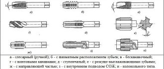
Types by design
Taps vary greatly in their design:
- Fluteless have very short grooves and are used for working with tough materials: light metal alloys and some low-carbon high-alloy steels.
- Helical - grooves are arranged in an ascending spiral; they are used to cut threads in blind holes on high-performance machines.
- Stepped. The working part is divided into two zones, the first cuts and the second smoothes.
- Combined - there is a drill in front of the lead-in part, in one pass a hole is made and a thread is cut into it.
- Broaches. Used for cutting threads in through holes using a lathe.
- With an internal cavity for coolant supply.
- Bell type. They are used for cutting large diameters (up to half a meter) and consist of several cutting systems mounted in a common mandrel.
There are other tap designs for rare and special applications.
Types of threads to be cut
There are different sets of taps for cutting each type and size of thread. They are not interchangeable, as are threaded elements of different types. The following main types are distinguished:
- Metric. The profile is in the form of an isosceles triangle with an angle at the apex of 60°, all profile dimensions are expressed in millimeters. Marked with the letter M.
- Inch. The profile has a more acute angle - 55°. The diameter is expressed in inches and their fractions in the form of simple fractions, and the pitch is expressed in the number of turns per inch. Some are marked with the letter W (in honor of J. Whitworth).
- Pipe. It is distinguished by different inclinations of the front and rear parts of the profile to ensure the reliability of the connection and prevent its spontaneous unwinding. There are both cylindrical and tapered pipe threads.
There are other thread types available for special applications.
Checking the thread pitch
In industry, for mechanical control and checking the thread pitch, a calibrator or profile dies (templates) are used, and the diameters are measured with a caliper.
In everyday life, the simplest method for determining dimensions is to screw a part with an unknown thread into an element with established parameters.
Another option for finding the pitch in the absence of inch thread gauges is to apply the part with the profile to a millimeter ruler and count the number of turns in a section 25.4 mm long.
If the type of thread is completely unknown, study its profile and take into account the type of part on which it is applied.
Typically, fastening bolts use a metric thread knurl with a triangular cross-section and a pointed tip. An inch thread with a cut off top is applied to pipeline fittings, and a variety with a rounded triangle peak is applied to pipes.
You can also use the tables above to determine the step. To do this, you need to measure the outer diameter with a caliper, then compare it with the tabular data and find out the pitch or number of threads per inch.
Stages of thread-cutting work with a clamp
Materials for the production of taps
The elements of the tap experience high mechanical and thermal loads; it must be capable of cutting several hundred holes during its operation, while a machine tap can cut many thousands of holes. Therefore, high-quality tool steels are used for their manufacture:
- For manual models - high-carbon U10A or U 12A.
- For machine machines - high-speed cutting PM5, etc.
- For high-performance automatic equipment - carbide with increased heat resistance.
Tapping threads
In addition to the advantages of high performance and durability, such materials also have one drawback - in the event of a breakdown, the tap for threading cannot be drilled.
How to cut threads by hand correctly and without wasting a tool
The technological process of thread cutting is divided into several operations.
- Preparation. Using the correspondence table, select a drill of the required diameter and accurately drill the hole, preventing the drill from slipping. The drill must be sharpened correctly, otherwise the material will overheat and the thread strength will decrease. Countersink the hole. In case of a blind hole, give an allowance for depth.
- To cut threads, use taps of standard sizes only.
- Slicing. Movements should be neat and measured. Do not skip numbers; all three should be used sequentially - from rough to final.
- After each full turn, the driver should be given a half turn in the opposite direction to chip the chips and push them out of the grooves.
- Cleaning. Pass-through holes are cleaned with a wire brush, blind holes are cleaned with an industrial vacuum cleaner or a stream of compressed air.
- Examination. Screw the screw into the hole. It should fit in without distortion and follow the thread smoothly and effortlessly.
Sequence of thread cutting with a tap
There are other secrets of hand-cutting in folklore, but to obtain high-quality carving it is enough to strictly follow the above
How to unscrew a broken tap
If you nevertheless violated the recommendations and broke the tap, do not despair. Despite the fact that it is almost impossible to drill out a broken tap - its strength is higher than that of a conventional drill, there are ways to save the situation.
- Extractor. For taps, a special extractor is used with hardened curved thin pins, which are inserted into the grooves at one end and clamped at the other in a special cylindrical mandrel. By carefully rotating the mandrel with a crank, you can unscrew the damaged instrument.
- Spot welding. An L-shaped rod is welded to the fragment, behind which the structure is unscrewed with pliers.
- Acid etching. An acid is selected that has a stronger effect on the material of the tap than on the material of the part. The method is dangerous and is not recommended for use in home workshops.
- Electric spark method. A minus is applied to the part, and the positive contact welding electrode is gently touched to the fragment. During an electric spark discharge, it loses tiny particles of metal in the form of hot splashes. After a few discharges, as a rule, the jamming disappears and the fragment can be unscrewed.
But the best way is not to break the tap at all.
Hole diameter for metric thread: size table according to GOST
Despite the fact that cutting internal threads is not a complex technological operation, there are some features of preparation for this procedure. Thus, it is necessary to accurately determine the dimensions of the preparation hole for threading, and also select the right tool, for which special tables of drill diameters for threads are used. For each type of thread, it is necessary to use the appropriate tool and calculate the diameter of the preparation hole.
The thread diameter and through hole must comply with the standards, otherwise the grooves will come out too small and the threaded connection will be unreliable
Preparing to cut internal threads
In order for the thread to be cut without problems, it is necessary to carefully prepare the hole.
A table of correspondence between drill diameters and a specific tap for metric, inch, pipe and trapezoidal threads is given at the link.
Download the table of threaded hole diameters
The drill must match the material of the part and be properly and well sharpened. The sharpening angle should be no more than 140°. This avoids overheating and involuntary heat treatment of the part material, leading to deterioration in thread quality.
The drill must be carefully secured; it is necessary to prevent runout of both the drill in the chuck and the chuck itself.
When drilling blind holes, you need to carefully control the depth and be sure to give an allowance in depth relative to the specified cutting depth - even the best tap will not cut the thread to the end.
You will need the following tools and supplies:
- Low speed drilling machine. The use of hand drills is not recommended.
- Drill selected according to the table.
- A drill of a larger diameter (about twice as large) for countersinking.
- Set of taps with a collar.
- Vise for securing the part.
- Core and hammer.
- Mineral oil to lubricate the tap and hole during operation.
- Wiping material.
The rules for cutting pipe threads generally coincide with those stated above, only for cutting large diameters special equipment is used for more accurate alignment
Threaded hole diameter: size table according to GOST and calculation
The strength of fastening the parts to each other is ensured by screwing the external thread carrier into the internal thread of the second product. It is important that their parameters are maintained in accordance with the standards, then such a connection will not be damaged during operation and will ensure the necessary tightness. Therefore, there are standards for the execution of carvings and its individual elements.
Before cutting, a hole is made inside the part for the thread, the diameter of which should not exceed its internal diameter. This is done using metal drills, the dimensions of which are given in the reference tables.
Features of the technology
The sequence of actions when passing an internal thread using a tap is as follows:
- Mark the hole.
- Hammer it with a hammer and core.
- Lubricate the part and drill.
- Secure the part in a vice or press it to the workbench with a clamp.
- Secure the drill in the machine chuck, set the lowest speed and start drilling; after the drill head is immersed in the metal, you can add more speed.
- Once drilling is complete, remove the chips and countersink the hole.
- Lubricate tap No. 1 and the part, align the tap strictly along the axis of the hole.
- Carefully begin the first turns of thread cutting with a tap. After each full turn, make a half turn in the opposite direction. Add lubricant every few turns.
- If the force on the driver increases sharply, it is necessary to move it back to throw off the chips.
- After passing No. 1, go through holes No. 2 and No. 3 in the same way.
The most important feature when cutting threads is thoroughness, accuracy, lack of haste and unnecessary effort. It's better to spend a few seconds making an extra half-turn back than to spend hours fiddling with a broken and jammed tap, removing it at the risk of damaging the part, and then finding yourself in front of the same hole again.
Selecting drill size
The diameter of the drill for a hole for a metric thread is also determined by formula (2), taking into account its main parameters.
It is worth noting that when cutting in ductile materials, such as steel or brass, the turns increase, so it is necessary to choose a larger drill diameter for the thread than for brittle materials, such as cast iron or bronze.
In practice, drill sizes are usually slightly smaller than the required hole. Thus, Table 2 shows the ratio of the nominal and outer thread diameters, the pitch, the diameters of the hole and the drill for cutting metric threads.
Table 2. The relationship between the main parameters of metric threads with normal pitch and the diameters of the hole and drill
Marking
The marking of taps begins with a letter indicating the type of thread. M for metric; G for pipe; Tr for trapezoidal. Taps for inch threads are marked without a letter.
Features of marking a tap for threading
Next comes the diameter in millimeters for metric and in inches with whole fractions for inch
If the thread has a non-standard pitch, the next step is the designation of the pitch in millimeters or in turns per inch.
If the tap is made of hardened stainless steel, HSS (Hardened Stainless Steel) is added to the marking
For left-hand thread taps, LH (Left Hand) is added at the end of the marking.
Designation on drawings
Due to the fact that when using tapered pipe threads, various types of such solders can be used, it is necessary to know the dimensions properly. According to GOST 6111-52, dimensions are indicated by a fraction, where the denominator is the outer diameter, and the numerator is its inner diameter.
Designations of pipe conical threads in the drawing are represented by letters such as:
- R – designation of conical thread with external thread.
- Rc – conical internal grooves are indicated.
- Rр – internal thread of a cylindrical profile.
- LH – cutting with a left spiral.
- RH – right-handed helix.
- MK – metric cone-shaped.
- M – metric.
- K – conical inch thread.
- Pipe conical thread – K pipes ½ GOST 6211-69.
- With a shortened profile - K pipes ½ cut GOST6211-69.
- Shortened conical with increased accuracy – K pipes ¾ in. exact GOST 6211-69.
Cylindrical threads are used directly together with external tapered threads, which have the same pitch.
Current standards
The design and parameters of taps for thread cutting are described in GOST 3266-81: “Machine and hand taps. Design and dimensions."
- Machine taps for metric threads - GOST 8859-74.
- Nut taps for metric threads - GOST 1604-71
- Nut taps with a curved shank for metric threads - GOST 6951-71.
Foreign standards DIN 352, ISO 529 and others do not contradict GOST, with the exception of the tail section being shorter by 1 cm
If you find an error, please select a piece of text and press Ctrl+Enter.
A tap is a tool that can be used to quickly and accurately cut a thread in a prepared hole. This is a rod divided into a working part and a shank. The shank is used for fixation in the driver or chuck of the machine. Chip removal is provided by longitudinal or helical grooves located on the cutting part. For the manufacture of this tool, carbon or high-speed steels are used. To cut internal threads efficiently, you need to know how to choose the right tap and prepare the hole.
Types of instruments
The appropriate tool is selected depending on the characteristics of the material being processed, the required productivity and other parameters. Using different types of taps, you can cut metric or inch internal threads with a cylindrical or conical profile.
According to the method of conducting the process, models are distinguished:
- Pass-through (universal) . Their working part consists of three zones. The first performs rough cutting, the second – intermediate, and the third – finishing.
- Complete . To perform a full range of work, several tools are used - for roughing, intermediate and finishing cutting. The sets consist of three taps, less often of two (for roughing and finishing). For processing particularly strong metals, kits with 5 tools are used.
The tool is made of two types: for processing holes manually or using metal-cutting equipment.
- Machine-manual . Has a square shank. Works complete with a holder with two handles - a knob.
- Machine . Installed in the chuck of metalworking machines of various types.
Taps of different designs are used for cutting threads in blind and through holes:
- For non-passable holes, use a complete tool without a conical tip. The work is usually done with a crank.
- In through holes, threads are made using taps with a conical tip. Most often these are varieties of universal type tools.
The channels for removing chips have different shapes: straight, screw, shortened.
Chip channels of any shape are suitable for processing materials of low hardness. To tap threads in high-hardness materials, such as stainless and heat-resistant steels, use only a tool in which the cutting segments are staggered.
Threading Tool Design
The cutting tap consists of several parts:
- Shank;
- Working part;
- Fence element;
- Calibrations
The shank is used to mount it in the spindle.
machine or chuck when it becomes necessary to cut internal threads.
The cutting is done by the working part. Its appearance resembles a screw, equipped with several helical and also longitudinal grooves.
A tool with helical grooves has one important advantage. The tapping operation is performed under more favorable conditions than performing the same operation with a thread tap that has longitudinal grooves.
Almost every instrument has a front part, which is given the name “fence”. It has a conical appearance. The intake part of the tool is the first to start threading. It is continued by the calibrating part. Its functions include calibrating and cleaning the hole.
The teeth used to cut threads are called cutting feathers
. Their shape resembles incisors located along the entire diameter of the tool. Each tooth is sharpened according to the technological requirements for cutting parts.
The recesses that separate the cutting feathers from each other are called grooves. They form cutting edges, and chips are removed from the cutting zone along them. The dimensions of the grooves can be seen in the corresponding standardized tables.
Small parts with a diameter of less than 20 mm are equipped with three grooves. Tool with a maximum diameter of 40 mm, manufactured with four grooves
.
Metric taps
They are measured in millimeters and refer to the metric system. The instrument is marked with the letter "M", indicating a metric measurement. For example, the M8 marking means that this tool can produce an 8 mm thread.
The size range of metric taps has a wide range. From 2 mm to 60 mm
. That is, you can cut absolutely any thread. All data about such a tool is summarized in special tables.
Depending on the purpose, the design of the tap is selected. They are divided into several groups:
- Machine;
- Manual.
Only hand tools are used for locksmith work.
. It, in turn, is divided into several types:
- Nut;
- Spot;
- Uterine;
- Special.
Locksmith
A set of such hand taps usually consists of three tools:
- Chernovoy;
- Average;
- Finishing.
First, the “black” thread is cut, for which a roughing tap is used
. To obtain thread accuracy, use a medium tap. The final cutting of the thread is carried out using a finishing tap and its calibration is carried out.
A special mark is made on the shank of each tap, by which the type of tap is determined. It can be digital or in the form of printed circular rings. The number of marks determines the purpose of the tap:
- Chernova – one ring;
- Finish - three rings.
In addition, the size of the thread that can be cut with this tap is marked on the tail.
Bench taps are supplied with two tools. They have a slightly longer intake cone, as well as an increased size of the first tap.
When cutting metric threads in the range of 8 - 18 millimeters, single taps are used
.
For threads 6 - 24 mm, use two taps, one for roughing, the other for finishing.
Three taps cut threads in the range of 2 - 52 mm. Inch threads are also cut with several tools depending on the size. In more detail, what taps are needed can be seen in the guest table. It indicates the diameters, type of tap and the required kit.
Depending on the direction of the grooves, taps are divided into groups:
- Straight;
- Screw.
Moreover, the direction of the grooves also has different designs:
- Rights;
- Left.
Tools with helical grooves are in most cases used for cutting very precise threaded holes.
The cutting part of the tool is divided into two types:
- Conical;
- Cylindrical
Conical
They differ in the design of the intake part, which is made slightly elongated and has an incomplete thread, which gradually becomes a calibrating part. These taps are used to cut threads in through holes.
Cylindrical
This tool cuts threads in parts where a through hole is not required.
When cutting nuts, nut devices are used without the use of machine tools
. Thanks to the extended shank, the cut nuts remain on the tool.
The die parts have a large intake cone. With this tool, preliminary thread cutting is carried out in dies. The operation is performed in one pass. The threads are cleaned with master parts having grooves in the form of a right-hand spiral.
In addition to ordinary machine tools, grooveless tools are also used. They do not have longitudinal grooves. Moreover, their receiving cone is made much shorter. These tools are highly durable
, they break very rarely, so the number of defective parts due to such a breakdown is minimized. The threaded part is long, making it possible to resharpen such tools several times.
The main advantage of grooveless parts is their high productivity. They can cut threads in any holes. For such a tool, a through or blind hole does not matter.
Universal parts are manufactured as prefabricated parts. Each part is separated by a special neck. The roughing operation is performed by the first part, preliminary cutting is carried out, and the second part is done by finishing the thread.
Working with such equipment saves time
. After all, only one tool is needed to cut threads. There is no need for a whole set, the installation of which requires a lot of additional time.
Pipe taps
Inches are taken for measurements, since pipes use a different system of change.
All pipe parts are marked with the letter G, which indicates pipe threads. Here are some examples:
- G 1/2 – half-inch thread;
- G 3/4″ – three-quarter;
- G1 – inch.
Half-inch pipe threads are most commonly used. This is especially true for plumbing in residential buildings, where the pipes are of such dimensions.
The pipe tap kit contains two parts. One has a sharp approach, the other is blunt.
As mentioned above, there are a lot of varieties of such instruments. Therefore, when making a choice, it is worth turning to special tables. They will tell you which tool you need to take, what diameter and what type.
The article talks about things you need to know when working with tapered threads. But first, we should consider what a metal threaded connection is now used for.
Iron pipes can currently only be found in houses that have not been renovated for several decades. Iron was replaced by pipes made of metal-plastic and polypropylene. Recent developments allow for complete sealing of the connection, which has led to the abandonment of steel as a material for risers and other systems.
But in places where the required reliability exceeds normal values, the use of metal continues and is often the only way out of the situation.
There are two main reasons for this:
- mechanical loads from the outside;
- high pressure values in the pipeline.
For example, a passing vehicle could easily crush a shallowly buried plastic pipe, whereas the pipe would most likely withstand the load.
It is worth considering that welding to connect sewer and water pipes is not possible or desirable everywhere. This may result from inability to access the welding site or danger of explosion. Also, it is often necessary to create a detachable connection that allows various measuring devices to be connected to the pipe as needed. Connections through threads are used for this purpose. The feature in the form of smooth thread edges ensures a tight connection using sealants or special ones.
How to correctly determine the hole diameter?
Before cutting a thread, a hole is made, the diameter of which is determined according to standardized tables. If you prepare a hole whose cross-section is smaller than the recommended size, the tool will fail; if it is larger, the result will be of poor quality.
Correspondence table for metric threads and hole diameters for them
| Thread designation | Diameter, mm | Thread designation | Diameter, mm | Thread designation | Diameter, mm |
| M 2 | 1,6 | M 8 | 6,7 | M 22 | 19,4 |
| M 2.2 | 1,75 | M 9 | 7,7 | M 24 | 20,9 |
| M 2.5 | 2,05 | M 10 | 8,5 | M 27 | 23,9 |
| M 3 | 2,5 | M 11 | 9,5 | M 30 | 26,4 |
| M 3.5 | 2,9 | M 12 | 10,2 | M 33 | 29,4 |
| M 4 | 3,3 | M 14 | 12,0 | 31,9 | |
| M 5 | 4,2 | M 16 | 14,0 | M 39 | |
| M 6 | 5,0 | M 18 | 15,4 | M 42 | 37,4 |
| M 7 | 6,0 | M 20 | 17,4 | M 45 | 40,4 |
Correspondence table for inch threads and hole diameters for them
| Thread size, inches | Diameter, mm | Thread size, inches | Diameter, mm |
| 1/8 | 8,8 | 7/8 | 28,1 |
| 1/4 | 11,7 | 1 | 30,5 |
| 3/8 | 15,2 | 1 1/8 | 35,2 |
| 1/2 | 18,9 | 1 1/4 | 39,2 |
| 5/8 | 20,7 | 1 3/8 | 41,6 |
| 3/4 | 24,3 | 45,2 |
Hole parameters
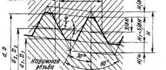
The following thread parameters are distinguished:
- diameters (internal, external, etc.);
- profile shape, height and angle;
- step and entry;
- others.
The condition for connecting parts to each other is the complete coincidence of the external and internal threads. If any of them are not performed in accordance with the requirements, the fastening will be unreliable.
The fastening can be bolted or stud, which, in addition to the main parts, includes nuts and washers. Before joining, holes are formed in the parts to be fastened, and then cutting is carried out.
To perform it with maximum accuracy, you should first form a hole by drilling, equal to the size of the internal diameter, that is, formed by the tops of the protrusions.
When performing a through design, the diameter of the hole must be 5-10% larger than the size of the bolt or stud, then the following condition is met:
where d is the nominal diameter of the bolt or stud, mm.
To determine the hole size of the second part, the calculation is carried out as follows: the pitch value (P) is subtracted from the value of the nominal diameter (d) - the resulting result is the desired value:
The calculation results are clearly demonstrated by the table of threaded hole diameters, compiled according to GOST 19257-73, for sizes 1-1.8 mm with small and main pitches.
An important parameter is the drilling depth, which is calculated from the sum of the following indicators:
- screw-in depth;
- reserve of external thread of the screwed-in part;
- her undercut;
- chamfers.
In this case, the last 3 parameters are for reference, and the first is calculated through the coefficients for taking into account the material of the product, which are equal for products from:
- steel, brass, bronze, titanium – 1;
- gray and ductile cast iron – 1.25;
- light alloys – 2.
Stages of thread cutting with a machine-hand tap
Work order:
- The first step is marking in accordance with the drawings.
- According to the marks, punching is carried out with a sharply sharpened core.
- Drill with medium pressure at low speeds. The drill should be at right angles to the surface. Before starting work, the drill is lubricated. If the hole depth is large, then lubrication is carried out not only before starting, but also during operation. The depth of the blind hole should be slightly greater than the length being cut. If there is no reserve, the thread may be incomplete.
- The quality of the result can be improved by countersink processing, which reduces the taper and ensures parallelism of the side surfaces.
- The tap is secured in the driver, its tip is lubricated and inserted into the hole strictly at right angles to the surface. Make the first turn, lightly pressing the knob from above. After the first turn forward, make a half turn back to remove chips. Particular care is taken when using a multi-tool - it is fragile and easy to damage. It's easier to work with complete models.
Types and classification: inch Fanuc and others
According to the shape of the surface of the pipe on which the thread is made, it can be:
- Cylindrical – traditional cutting on rolled products of constant diameter;
- Conical - here the base is a conical pipe, that is, one whose outer diameter gradually decreases towards the end.
In this case, internal and external screw threads are distinguished in accordance with their location on the walls. There can be only one purpose: the internal tapered pipe thread, like the external one, forms fastening and sealing connections.
According to the linked measurement system, two types of threaded pipes are produced:
- Metric (with a profile angle of 60º) is the most common type of connection used in our country in the production of new equipment.
- Inch (α=55º), whose outer diameter and other parameters are tied to the English system of measures, that is, expressed in inches. Conical inch threads are different in that they are not tied to the cutting pitch. Instead, the number of turns per unit length is used.
The direction of the turns can be right, less often left. You should also take into account the number of their visits.
Normal
For diameters from 1" to 6" a thread of 11 threads per inch is more often used.
Small
It is distinguished by a large number of turns per unit length due to the reduced cutting step. This is done to maintain the thickness and strength of the walls, maximum tightness of connections or fine adjustment of the relative position of parts.
For pipes with a diameter of no more than an inch (½ʺ and ¾ʺ), 14 turns are accepted, but cutting 19 and 28 threads is possible with d from 1/16ʺ to 3/8ʺ.
Useful tips
- In order to correctly cut threads in metals with low hardness and high viscosity, such as aluminum, alloys based on it, copper, babbitt, it is recommended to periodically remove the tap to clean the channels from adhering chips.
- When using complete models, the complete set should be used. Skipping the roughing tool does not speed up, but slows down cutting. Such a violation of technology leads to a decrease in the quality of the result, and sometimes to failure of the tap.
- To prevent the tap from skewing, check the verticality of its position after 2-3 threads using a square. This precaution is especially important for blind and small holes.
The process must be carried out using liquids intended for lubrication and cooling:
- emulsions, linseed oil, and drying oil are used in steel elements;
- in products made of aluminum and its alloys - kerosene;
- when processing copper - turpentine.
It is possible to cut threads in parts made of cast iron or bronze without the use of lubricant.
Methods for cutting tapered pipe threads
Unlike standard cylindrical threads, where the diameter is the same throughout the entire length of the part, conical threads are made taking into account the characteristics of the connection. It is performed on machines that allow the movement of the support at a given angle, or with the help of metalworking tools: dies and taps
When cutting tapered threads, it is important to accurately observe the direction of movement and position of the tool. Control the process using a square. Deviations seriously impair quality and the thread can no longer be used in critical connections
The working tool may consist of a set of taps, dies with numbers indicated on them
Deviations seriously degrade the quality and the thread can no longer be used in critical connections. The working tool may consist of a set of taps and dies with the numbers indicated on them.
How to cut threads yourself? First of all, it is necessary to securely fix the part in a vice in such a way as to ensure access to the measuring square. If you have a drilling machine, then it is enough to clamp it without distortions. When using a drill, it is more difficult to control the angle. You can use additional devices, for example, a jig or a guide coupling. Particular care should be taken when finishing passes with a conical drill or reamer. An accurately made hole will allow the tap to make the correct entry. When the slope of the outer cone of the part corresponds to the specified angle, the die will easily self-orient along it and the thread will be of high quality.
Slicing equipment
In practice, an ordinary mechanic does not often have to make a conical thread, if the specifics of production are not related to the manufacture of parts with this type of connection. A home master encounters this operation even less often. A table for determining diameters will be an assistant in your work.
| Size in inches | Hole diameter, mm | Drilling depth, mm | |
| dc | do | ||
| ⅛ | 8,10 | 8,57 | 15 |
| ¼ | 10,80 | 11,45 | 20 |
| ⅜ | 14,30 | 14,95 | 24 |
| ½ | 17,90 | 18,63 | 29 |
| ¾ | 23,35 | 24,12 | 31 |
| 1 | 29,35 | 30,29 | 37 |
| 1¼ | 37,80 | 38,95 | 40 |
| 1½ | 43,70 | 44,85 | 42 |
| 2 | 55,25 | 56,66 | 44 |
The largest diameter of the cone is denoted by do, and the smallest by dc. To facilitate the entry of the tool, a chamfer is made. It is difficult and time-consuming to make a tap in a cylindrical hole. To reduce labor intensity and speed up the operation, use conical drills and reamers of the required size. If the tool is complete, then first take a tap or die with number 1. This is rough cutting. Then they pass with tool No. 2. Sometimes a set may contain 3 types of taps. In non-ferrous metals, tapered threads can be made in one pass if cutting fluids are used. When working with steel, it is advisable to go through the hole sequentially with all taps.
You can also see the cone from the jaws for internal measurements. It is enough to insert them inside and you will see the slope on the die relative to the parallel jaws of the caliper. Conical dies are wider than regular dies because they must completely cover the length of the workpiece. They are harder to work with. The load is distributed over the entire cutting surface, so use a powerful wrench with long handles, or extend them to create a lever. Designated machine die 2684-0015, manual 2684-0015r. All characteristics are specified in GOST 6228-80. The tap has the abbreviation 2680-0016. Technical characteristics are described in GOST 6227-80.
Conical connections are used in critical components, so the requirements for surface finish are high. This can only be achieved by using high-quality cutting fluids. The choice of compositions is wide. But if professional materials are not at hand, then at home you can use animal fat for work. According to its characteristics, it is excellent for this purpose. Many experienced masters often use it in their practice. It guarantees good glide and high-quality cutting of metal without chipping.
The cutting tool is made of tool, high-speed steels. GOST specifies the recommended service life of dies and taps. It is calculated for a tool made of R6M5 alloy using workpieces made of steel 45. The die must be guaranteed to process from 125 (more than 1 inch) to 225 (less than an inch) external threads that meet the requirements of GOST. Accordingly, if more durable alloys of parts are used in the work, the service life decreases. To check the quality of processing, geometric dimensions and compliance with the profile, special templates are used - calibers. The same devices are used when sharpening cutters for lathes.