Bolt table with thread pitches for bolts, nuts, screws and threaded rods.
How to determine the thread size without a thread gauge, read our special article.
| Thread diameter | Thread pitch, mm | |||
| Main thread pitch, mm / Thread hole diameter, mm | Fine thread pitch, mm / Thread hole diameter, mm | |||
| Small | Petty 2 | Superfine | ||
| M 1 | 0.25 / 0.75 | (0.2) / 0.8 | — | — |
| M 1.2 | 0.25 / 0.95 | (0.2) / 1 | — | — |
| M 1.4 | 0.3 / 0.9 | (0.2) / 1.2 | — | — |
| M 1.6 | 0.35 / 1.2 | (0.2) / 1.4 | — | — |
| M 1.8 | 0.35 / 1.5 | (0.2) / 1.6 | — | — |
| M 2 | 0.4 / 1.6 | (0.25) / 1.75 | — | — |
| M 2.2 | 0.45 / 1.75 | (0.25) / 1.95 | — | — |
| M 2.5 | 0.45 / 2.05 | (0.35) / 2.15 | — | — |
| M 3 | 0.5 / 2.5 | (0.35) / 2.65 | — | — |
| M 3.5 | 0.6 / 2.9 | (0.35) / 3.15 | — | — |
| M 4 | 0.7 / 3.3 | 0.5 / 3.5 | — | — |
| M 4.5 | 0.7 / 3.8 | — | — | — |
| M5 | 0.8 / 4.2 | 0.5 / 4.5 | — | — |
| M 5.5 | — | (0.5) / 4.5 | — | — |
| M 6 | 1 / 5 | 0.75 / 5.2 | 0.5 / 5.5 | — |
| M 7 | 1 / 6 | (0.75) / 6.2 | 0.5 / 6.5 | — |
| M 8 | 1.25 / 6.7 | 1 / 7 | 0.75 / 7.2 | 0.5 / 7.5 |
| M 9 | 1.25 / 7.7 | 1 / 7.95 | 0.75 / 8.2 | 0.5 / 8.5 |
| M 10 | 1.5 / 8.5 | 1.25 / 8.7 | 1 / 9 | 0.75 / 9.2 |
| M 12 | 1.75 / 10.2 | 1.5 / 10.5 | 1.25 / 10.7 | 1 / 11 |
| M 14 | 2 / 12 | 1.5 / 12.5 | 1.25 / 12.6 | 1 / 13 |
| M 15 | — | 1.5 / 13.4 | 1 / 13.95 | — |
| M 16 | 2 / 14 | 1.5 / 14.5 | — | 1 / 15 |
| M 18 | 2.5 / 15.4 | 2 / 16 | 1.25 / 16.6 | 1 / 17 |
| M 20 | 2.5 / 17.4 | 2 / 18 | 1.25 / 18.6 | 1 / 19 |
| M 22 | 2.5 / 19.4 | 2 / 20 | 1.5 / 20.5 | 1 / 21 |
| M 24 | 3 / 20.9 | 2 / 22 | 1.5 / 22.5 | 1 / 23 |
| M 27 | 3 / 23.9 | 2 / 25 | 1.5 / 25.5 | (1) / 26 |
| M 30 | 3.5 / 26.4 | 2 / 28 | 1.5 / 28.5 | (1) / 29 |
| M 33 | 3.5 / 29.4 | 2 / 31 | 1.5 / 31.5 | — |
| M 36 | 4 / 31.9 | 3 / 33 | 2 / 34 | 1.5 / 34.5 |
| M 39 | 4 / 34.9 | 3(4) / 35.9 | 2 / 37 | 1.5 / 37.5 |
| M 42 | 4.5 / 37.4 | 3(4) / 37.9 | 2 / 40 | 1.5 / 40.5 |
| M 45 | 4.5 / 40.4 | 3(4) / 40.9 | 2 / 43 | 1.5 / 43.5 |
| M 48 | 5 / 42.8 | 3 / 44.9 | 2 / 46 | 1.5 / 46.5 |
| M 52 | 5 / 46.8 | (4)3 / 48.9 | 2 / 50 | 1.5 / 50.5 |
| M 56 | 5.5 / 50.4 | 4 / 51.9 | 3(2) / 53 | 1.5 / 54.5 |
| M 60 | 5.5 / 64.4 | 4 / 55.8 | 3(2) / 67 | 1.5 / 58 |
| M 64 | 6 / 57.8 | 4 / 59.8 | 3 / 61 | 2(1.5) / 62 |
| M 68 | 6 / 61.8 | 4 / 63.8 | 3 / 65 | 2(1.5) / 66 |
Full table with threads from M0.25 to M600 is available in PDF
The letter “M” near the thread diameter lets us know that the thread is metric, i.e. not inch, but metric
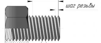
Metric thread pitch
Metric thread pitch is the distance in millimeters between two identical points located on the same side adjacent turns of the profile. Measured parallel to the thread axis. This is one of the key parameters of a threaded product, along with diameters (nominal, internal, external), direction of rotation, profile type, number of strokes. GOST 8724-2002 indicates the compliance of these characteristics in the range of diameters from 0.25 to 600 mm and pitches from 0.075 to 8 mm.
In accordance with the regulatory document, manufacturing enterprises can produce fasteners with 2 types of metric thread pitches - small and large. For one size of fastener, the standard defines only one large and several small thread pitches. For fasteners with a nominal diameter of less than 1 mm, in accordance with GOST, only large ones are installed, from 1 mm to 64 mm - large and small, from 72 mm to 600 mm - only small.
Thread length: 8.8, 10.9 high strength nut bolts
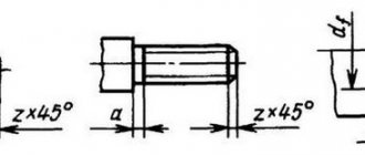
The thread length is the length of the surface area on which the thread is formed, including the thread runout and chamfer. As a rule, only the full profile thread length is indicated on the drawings.
It is possible to produce bolts with long threads: standard, full, without thread.
Thread length:
| Standard | The standard thread length of bolts of the same size group is the same regardless of the length of the bolts. When designating bolt parameters, the standard thread length is not indicated. Standard threads are widely used in fasteners |
| Full | Full thread is called a thread up to the bolt head. When designating bolt parameters, it is additionally used when the fastener or bolt is screwed into the body; when installing clamps for plumbing equipment; when tightening materials of different thicknesses. |
The calculation of thread parameters is based on the nominal thread diameter, thread pitch and internal thread diameter:
| D… Nominal outer diameter of internal thread (nut) d… Nominal outer diameter of male thread (bolt) D/d Nominal thread diameter D2/d2 Nominal mean thread diameter D1/d3 Nominal internal thread diameter )> Thread pitch |
The value of metric thread diameters is calculated using the formulas:
D2 (d2) = D(d) - 0.6495P D1 (d1) = D(d) - 1.0825P
External thread (bolt) dimensions are measured with gauges, micrometers or optical gauges, while internal thread (nut) dimensions are measured with cylindrical gauges.
METRIC THREAD DIAMETER CALCULATOR
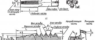
Metric thread is the most common. It is used in the manufacture of hardware, shafts, fittings for high-pressure hoses, instrument parts, parts of measuring instruments, etc. A thread profile is a cross-section of a thread with a plane passing through the axis of the cylinder on which the thread is formed. The metric thread profile is triangular with a profile angle of 60°. Threads can be single-start or multi-start. Single-start threads are characterized by a pitch, while multi-start threads are characterized by a pitch and a stroke. The thread pitch is the distance between adjacent turns. The thread lead is the distance between turns of one thread. The stroke is equal to the distance that the bolt or nut moves along the axis in one revolution. The stroke is equal to the pitch multiplied by the number of thread starts. The stroke and pitch of a single-start thread are equal.
Figure 1 - Pitch and thread progress
Threads can also be right-handed or left-handed. The thread is also characterized by such a parameter as the angle of the thread. This angle is determined by the formula:
Using the calculator on the website you can calculate thread parameters according to GOST 24705-2004. This GOST defines the parameters of a metric cylindrical thread for general purpose with a profile angle α = 60°
Figure 2 - Thread parameters
When calculating, the following letter designations are used:
- D is the nominal diameter of the internal thread;
- d is the nominal diameter of the external thread;
- D 2 - average diameter of internal thread;
- d 2 - average diameter of external thread;
- D 1 - internal diameter of the internal thread;
- d 1 - internal diameter of the external thread;
- d 3 - internal diameter of the external thread along the cavity;
- S—thread stroke;
- P - thread pitch.
d 3 is used for strength calculations. When making calculations, it is also necessary to take into account the upper deviation of the average diameter according to GOST 16093-2004.
| Thread(steps) | Thread(steps) | Thread(steps) | Thread(steps) | Thread(steps) |
| 0.25(0.075) | 0.3(0.08) | 0.35(0.09) | 0.4(0.1) | 0.45(0.1) |
| 0.5(0.125) | 0.55(0.125) | 0.6(0.15) | 0.7(0.175) | 0.8(0.2) |
| 1(0.25, 0.2) | 1.1(0.25, 0.2) | 1.2(0.25, 0.2) | 1.4(0.3, 0.2) | 1.6(0.35, 0.2) |
| 1.8(0.35, 0.2) | 2(0.4, 0.25) | 2.2(0.45, 0.25) | 2.5(0.45, 0.35) | 3(0.5, 0.35) |
| 3.5(0.6, 0.35) | 4(0.7, 0.5) | 4.5(0.75, 0.5) | 5(0.8, 0.5) | 5.5( — , 0.5) |
| 6(1, 0.75, 0.5) | 7(1, 0.75, 0.5) | 8(1.25, 1, 0.75, 0.5) | 9(1.25, 1, 0.75, 0.5) | 10(1.5, 1.25, 1, 0.75, 0.5) |
| 11(1.5, 1, 0.75, 0.5) | 12(1.75, 1.5, 1.25, 1, 0.75, 0.5) | 14(2, 1.5, 1.25, 1, 0.75, 0.5) | 15(1.5, 1) | 16(2, 1.5, 1, 0.75, 0.5) |
| 17(1.5, 1) | 18(2.5, 2, 1.5, 1, 0.75, 0.5) | 20(2.5, 2, 1.5, 1, 0.75, 0.5) | 22(2.5, 2, 1.5, 1, 0.75, 0.5) | 24(3, 2, 1.5, 1, 0.75) |
| 25(2, 1.5, 1) | 26(1.5) | 27(3, 2, 1.5, 1, 0.75) | 28(2, 1.5, 1) | 30(3.5, 3, 2, 1.5, 1, 0.75) |
| 32(2, 1.5) | 33(3.5, 3, 2, 1.5, 1, 0.75) | 35(1.5) | 36(4, 3, 2, 1.5, 1) | 38(1.5) |
| 39(4, 3, 2, 1.5, 1) | 40(3, 2, 1.5) | 42(4.5, 4, 3, 2, 1.5, 1) | 45(4.5, 4, 3, 2, 1.5, 1) | 48(5, 4, 3, 2, 1.5, 1) |
| 50(3, 2, 1.5) | 52(5, 4, 3, 2, 1.5, 1) | 55(4, 3, 2, 1.5) | 56(5.5, 4, 3, 2, 1.5, 1) | 58(4, 3, 2, 1.5) |
| 60(5.5, 4, 3, 2, 1.5, 1) | 62(4, 3, 2, 1.5) | 64(6, 4, 3, 2, 1.5, 1) | 65(4, 3, 2, 1.5) | 68(6, 4, 3, 2, 1.5, 1) |
| 70(6, 4, 3, 2, 1.5) | 72(6, 4, 3, 2, 1.5, 1) | 75(4, 3, 2, 1.5) | 76(6, 4, 3, 2, 1.5, 1) | 78(2) |
| 80(6, 4, 3, 2, 1.5) | 82(2) | 85(6, 4, 3, 2, 1.5) | 90(6, 4, 3, 2, 1.5) | 95(6, 4, 3, 2, 1.5) |
| 100(6, 4, 3, 2, 1.5) | 105(6, 4, 3, 2, 1.5) | 110(6, 4, 3, 2, 1.5) | 115(6, 4, 3, 2, 1.5) | 120(6, 4, 3, 2, 1.5) |
| 125(8, 6, 4, 3, 2, 1.5) | 130(8, 6, 4, 3, 2, 1.5) | 135(8, 6, 4, 3, 2, 1.5) | 140(8, 6, 4, 3, 2, 1.5) | 145(6, 4, 3, 2, 1.5) |
| 150(8, 6, 4, 3, 2, 1.5) | 155(6, 4, 3, 2) | 160(8, 6, 4, 3, 2) | 165(6, 4, 3, 2) | 170(8, 6, 4, 3, 2) |
| 175(6, 4, 3, 2) | 180(8, 6, 4, 3, 2) | 185(6, 4, 3, 2) | 190(8, 6, 4, 3, 2) | 195(6, 4, 3, 2) |
| 200(8, 6, 4, 3, 2) | 205(6, 4, 3) | 210(8, 6, 4, 3) | 215(6, 4, 3) | 220(8, 6, 4, 3) |
| 225(6, 4, 3) | 230(8, 6, 4, 3) | 235(6, 4, 3) | 240(8, 6, 4, 3) | 245(6, 4, 3) |
| 250(8, 6, 4, 3) | 255(6, 4, 3) | 260(8, 6, 4, 3) | 265(6, 4, 3) | 270(8, 6, 4, 3) |
| 275(6, 4, 3) | 280(8, 6, 4, 3) | 285(6, 4, 3) | 290(8, 6, 4, 3) | 295(6, 4, 3) |
| 300(8, 6, 4, 3) | 310(6, 4) | 320(8, 6, 4) | 330(6, 4) | 340(8, 6, 4) |
| 350(6, 4) | 360(8, 6, 4) | 370(6, 4) | 380(8, 6, 4) | 390(6, 4) |
| 400(8, 6, 4) | 410(6) | 420(8, 6) | 430(6) | 440(8, 6) |
| 450(6) | 460(8, 6) | 470(6) | 480(8, 6) | 490(6) |
| 500(8, 6) | 510(6) | 520(8, 6) | 530(6) | 540(8, 6) |
| 550(6) | 560(8, 6) | 570(6) | 580(8, 6) | 590(6) |
| 600(8, 6) |
The diameters of holes for threads can be found in GOST 19257-73
Calculation of thread diameters, input thread parameters D=d P calculated diameters D 2 = d 2 D 1 = d 1 d 3
Basic thread parameters taken into account when connecting parts:
Thread tolerance
Tolerances are established for two thread diameters - the average diameter and the diameter of the projections (outer diameter of the external thread and internal diameter of the internal thread).
The mean thread diameter tolerance determines the permissible degree of deviation of the nominal mean diameter of the external (d2) and internal threads (D2).
The tab diameter tolerance specifies the allowable amount of variation between the nominal outside diameter (d) of an externally threaded fastener (e.g., bolts, screws) and the nominal inside diameter (D) of an internally threaded fastener (e.g., a nut).
The mean and shoulder diameter tolerance values are always negative for male fasteners and positive for female fasteners.
A positive tolerance for internal threads and a negative tolerance for external threads allows you to leave the necessary tolerance for possible subsequent processing.
| 0 - zero mark (h/H) - Nominal diameter. +/- - positive/negative tolerance zones. e/g/G — tolerance position relative to 0 (h/H) 6/7/8 - degree of tolerance accuracy * - standard bolt/nut tolerance size Es/ei - maximum size of the tolerance zone boundary Ei/es - minimum size of the tolerance limit |
Tolerance field
The distance between the maximum and minimum value of the set limit (field size es-ei/EI-ES) determines the tolerance range. The thread tolerance field is formed by a combination of the tolerance fields of the average diameter and the diameter of the protrusions.
The position of the thread diameter tolerance field is determined by the main deviation (upper for external threads and lower for internal threads) and is indicated by a letter of the Latin alphabet, lowercase for external threads and uppercase for internal threads.
The designation of the tolerance field of an individual thread diameter consists of a number indicating the degree of accuracy and a letter indicating the main deviation. For example, 4h; 6g; 6H.
The designation of the thread tolerance field consists of the designation of the tolerance field of the average diameter placed in the first place, and the designation of the tolerance field of the diameter of the protrusions.
7g 6g (tolerance range d2 and d).
If the designation of the tolerance field for the diameters of the protrusions coincides with the designation of the field for the average diameter, then it is not repeated in the designation of the thread tolerance field.
Recommended tolerance ranges for make-up length N (before applying anti-corrosion coating) for fasteners with DIN, ISO, DIN ISO, DIN EN ISO, GOST standards:
| Accuracy class: | Average | Rude | ||
| Thread | Nominal outer diameter of external thread (screw, bolt) | Nominal outside diameter of internal thread(nut) | Nominal outer diameter of external thread (screw, bolt) | Nominal outside diameter of internal thread(nut) |
| Without cover | 6g | 6H | 8g | 7H |
| Thin electroplated coating | ||||
| Large sizes (uncoated) | 6e | 6G | 8e | 7G |
| Thick electroplated coating | ||||
| Product accuracy class: | A, B | C | ||
| GOST | 7798-70, 7805-70 | 5915-70, 5927-70 | 15589-70 | |
| DIN | 931, 933 | 934 | 558, 601 | 555 |
| ISO | 4014, 4017 | 4032 | 4018, 4016 | 4034 |
DIN pipe fittings
International DIN tube fittings have a 24° tapered neck on the inside of the male fitting, which should clearly identify it as DIN if metric threads have also been identified. To determine which series and tube size a fitting is, you should examine the tube nut: most manufacturers indicate the series and tube size on the product itself. The system used for this marking combines a series of pipes with a male threaded tube, for example: the size of a 15mm tube in the L series is reduced to L15.
If the series and size are not indicated on the part, you need to match the pipe with the metric thread leader (thread size and thread pitch in mm).
Using the caliper and pitch sensor
These devices are quite simple to operate, but with their help you can make accurate calculations faster. To do this you need:
- Determine whether the threads are conical. To use a caliper, you need to place the measuring tool points on either side of the object that is being identified. The device must be aligned on the outside of the threads at the lower end, away from the head. It displays the width. Next, you need to move the tip until it touches the threads. The readings will pop up on the display if the instrument is digital. If it is a mechanical device, you need to read the data on the sliding part. Next, you need to do a similar action on the threaded area near the screw head. If the indicator is higher near it, then you are dealing with a tapered thread. If it is parallel, then the rod does not taper.
- Tapered threads are measured on the 4th or 5th thread down from the head, essentially in the center of the threaded area. If the fastener does not become narrower, you can take measurements at any point along the entire thread. Using a support allows you to notice that there are several points where the threads are not located closely. You should not place what you want to measure within the specified intervals. It is necessary to keep your hands close to the threads.
- Press the thread pitch sensor to find the pitch. The pitch sensor has little knobs that pull out. Each of them has teeth corresponding to specific steps. You should try to insert the teeth into the threads until you find one that matches. The number for this step will be on the handle. It will be in TPI or Metric, depending on the type of pitch sensor that is used.
- Place the obtained indicators into a standardized measurement. Once the pitch is determined, the length of the screw from under the head can be calculated, and then the numerical values can be placed into a standard measurement, which is diameter, thread pitch or TPI, and length. If you are measuring a metric screw or bolt with a diameter of 4mm, a thread pitch of 0.4mm and a length of 8mm, then the measurement will be M4 X 0.4 X 8M.
Many people believe that the metric system is actually simpler because many measurements are in the same unit and there are no fractions to complicate calculations.
At the First Fasteners store you will find a wide selection of fasteners: from standard bolts and nuts to anchors and fastening systems.
Kobelco and Komatsu fittings
Kobelco fittings are essentially the same as 24° DIN metric pipe fittings, however all Kobelco thread sizes are 1.5mm pitch. All pipe accessories for Kobelco fittings are L series and are completely interchangeable. However, there are some sizes that are truly unique to Kobelco.
Komatsu fittings have a thread pitch of 1.5 mm in all sizes and seals through a 30°/60° cone seat. If they are identified as a metric nose cone thread, extreme care must be taken to discern whether it is actually a 30°/60° (Komatsu) cone seat instead of a 37°/74° (GB Chinese) seat.
Application
Metric threads are widespread in the countries of the former Soviet Union. Used for application to both internal and external planes of fasteners. Typically used for fastening metal structures of various types. For these purposes, a variety of bolts (anchor and conventional) and other types of fasteners are manufactured. She found a particular purpose in mechanical engineering, construction of engineering communications, especially in the plumbing sector. Most pipe and container fittings are manufactured with this type of thread.
Most often, this type of carving is applied to cylindrical objects. But in some cases, when it is necessary to achieve tightness, a conical shape is used. This form, with a metric thread applied, allows you to achieve maximum tightness, even without the use of additional sealing agents. Most often used for installation of pipelines.
Tolerance fields
The fit of the outer profile into the inner one depends on the working height - the maximum amount of contact between the sides of the profiles of the connecting elements. It is expressed through thread tolerance fields.
The reliability of the connection, where fluctuations within it are minimized, is indicated by the first or exact tolerance class. The most common is the second (middle) class. The third (rough) class indicates a large deviation.
Tolerances on the dimensions of metric threads are indicated through the values of two diameters: the average and the diameter of the protrusions.
Read also: How to make a stationary one from a hand router
When forming a metric thread, data is taken from the corresponding tables (GOST 16093-2004). The selection of tolerance fields is carried out according to the rules of priority:
- first priority – values indicated in bold;
- the second - in regular font;
- third – values taken in parentheses;
- extraordinary – values in square brackets (for special products).
It is possible to use tolerances that are not indicated in the tables, but are formed from the ratios of existing standard diameters.
External thread tolerance fields
Internal thread tolerance fields
It is important that the protective coatings of parts in their geometric parameters do not exceed the value of the nominal profile, therefore in such cases tolerances are used even before applying the protective layer.
37°/74° and flat end Chinese metric fittings
These fittings are increasingly being exported from China using heavy equipment to Chinese standards. What defines these standards is that they both use North American sealing styles, but with metric threads. This includes O-ring face sealing (ORFS) and 37° flared seat (JIC) sealing methods, however UN and SAE threads are replaced by metric threads and do not follow traditional thread pitches in all sizes.
In Russia, these fasteners are also found, but much less frequently. They are produced in Chinese factories primarily for export and sale on the North American market.
State standards
GOST 8724-2002
State standard containing standards defining the required parameters of metric threads, including pitch and diameter. Adopted in 2002, with subsequent editions, as an analogue of the international standard ISO 261-98. The GOST text practically repeats the international text, with one difference: the ISO range ranges from 1 to 300 mm, this standard has been expanded to the range from 0.25 to 600 mm. The last revision of the text was made in 2004 and is valid today.
Read also: Injection gas burner drawing
The standard contains individual parameters that can also be found in other standards. The structure of the document is similar to other standards of this type. All information is structured in the form of tables containing requirements for thread pitch and diameter. This test structure is as convenient as possible for understanding and use.
It should be noted that the regulatory information applies to threads of all types, be it left-handed or right-handed. The standard establishes the standard value of metric thread steps in the range from 0.075 to 8 mm.
The document consists of:
- Prefaces. Which contains general information about GOST, by whom and when it was adopted, when changes were made.
- Scope of application. Information is provided on the range of regulatory requirements for size and pitch.
- Links to standards.
- Definitions.
- Table of diameters and pitch. The section contains a table of standard indicators.
- Thread designation. Labeling standards are indicated.
GOST 24705-2004
The standard was adopted in 2004. Its standards apply to all types of threads in accordance with GOST 8724. The text information is also structured in the form of a table. Complies with the international standard ISO 724:1993 with additions in accordance with the exclusive requirements of each member country of the Interstate Council for Standardization.
GOST 9150-2002
A standard regulating the requirements for the profile, namely the geometric parameters. Adopted in 2002 and covering all types of threads. The text of GOST is closely related to the above standards.
GOST 16093-2004
Adopted in 2004. Regulates the standard tolerance of threads and markings, applies to different types. The latest version contains the provisions of the international standard.
The above standards are applied in combination, as they complement and refer to each other.