Average diameter of threaded connection
To determine the average diameter of a thread, you need a micrometer with special tips in the form of a cone and a cutout. It is used to determine the size of the part at the top of the thread and at the root to calculate the average value. When selecting a kit, it is necessary to take into account the measurement limit, which is indicated in the marking with the letter M and numbers indicating the minimum and maximum allowable thread pitch. Also, to obtain the average thread value, calipers with ball tips are used, the profile of which matches the type and pitch of the thread. The tips are calibrated on several sides of the part for the most accurate result.
Measuring with a thread gauge
The best option for correctly measuring threads is to use a thread gauge. This is a special tool for measuring cutting pitch. The thread gauge is a body to which probes are attached in the form of thin plates with a comb. The shape of the comb exactly matches the standard thread with a certain pitch.
The following types of thread gauges are distinguished:
- Metric. Allows you to measure the thread pitch of a bolt, nut or other part with a metric thread with a diameter from 1 to 600 mm. The tool has up to 20 measuring plates and allows you to determine thread pitch from 0.4 mm to 7 mm. Indicated by the marking “M60” on the body.
- Inch. Used to measure inch threads, which are usually cut on pipes and pipeline parts, and are also sometimes used on fasteners. The pitch of an inch thread is determined by the number of threads per inch of length of the threaded part of the part. The thread gauge is equipped with 17 measuring plates with a number of turns from 4 to 28. The “D55” marking is used to mark the tool.
- Universal. Equipped with measuring plates for metric and inch cutting. Such thread gauges are widely used in workshops where it is necessary to simultaneously work with parts with both metric and inch threads.
Before determining the pitch, you need to measure the diameter of the thread with a caliper. This is necessary because the pitch range may depend on the diameter.
The process of measuring pitch using a thread gauge is extremely simple. Visually suitable thread gauge plates are applied to the thread being measured. Using the selection method, a plate is selected whose comb will exactly match the thread being measured. Its pitch will correspond to the standard value indicated on the marking of the measuring plate.
The easiest way to measure external threads is this way. If you need to determine the pitch of the internal thread, then the measurement location must be illuminated in order to accurately determine the tight fit of the thread gauge plate comb.
When measuring the pitch of a metric thread, the desired parameter is obtained in millimeters. If it is necessary to measure the pitch of an inch thread, then its value is obtained in the number of turns per inch.
Caliber
Unlike a micrometer, calipers and other instruments, for each diameter, type and thread pitch there is its own separate gauge, which is the standard of the maximum permissible value. To match the thread to the gauge, it is necessary that the latter can be screwed freely without any effort or gaps along the entire length. There are nut gauges and plug gauges for external and internal threads, respectively. The advantage of this method is the simplicity and accuracy of measurement. The main disadvantage is the need to use a set of gauges when checking more than one type and diameter of threaded connections.
Determination of thread pitch by diameter
The thread pitch can be determined using standard tables. First you need to measure the thread diameter of the bolt or nut. To do this, you need to use a caliper, which allows you to determine the size with high accuracy. The measurement accuracy should be tenths of a millimeter. After this, using the obtained value, you can find the thread pitch corresponding to the diameter in the table.
Example table for threads with outer diameter from 9.3 mm to 63.4 mm:
Inch thread table. Classification
An inch thread is a thread, all parameters of which are expressed in inches, the thread pitch is in fractions of an inch (inch = 2.54 cm). For inch pipe threads, the size in inches characterizes the clearance in the pipe, and the outer diameter of the pipe itself is slightly larger.
Inch threads are used in threaded connections and screw drives. Inch threads come in the following types:
- Inch cylindrical – UTS (Unified Thread Standard). This type of carving is widespread in the USA and Canada. The apex angle of this thread is 60 degrees. Depending on the step, it is divided into: UNC (Unified Coarse); UNF (Unified Fine); UNEF (Unified Extra Fine); 8UN; UNS (Unified Special). The most widely used thread is UNC. This thread conforms to ANSI 1 standard.
- British standard inch thread - BSW. Fine pitch threads are called BSF (British Standard Fine). The apex angle of this thread is 55 degrees.
- Inch tapered NPT or cylindrical NPS. Meets ANSI/ASME 20.1. This thread is used for pipe connections. Has an apex angle of 60 degrees. In Russia, such threads correspond to GOST 6111-52.
Most often in Russia recently you can find fasteners with inch UNC threads (unified coarse thread).
Such fasteners are often found on equipment imported into our country (lawn mowers, trimmers, generators, cultivators, American-made cars, etc.) from the USA, China and some other countries.
When working with inch fasteners, you must remember that the sizes of the keys for inch fasteners are different from the keys for metric fasteners.
The main dimensions of inch UNC fasteners are given in the table of inch threads
Standard size Outer diameter, inches Outer diameter, mm Drilling diameter, mm mm Number of turns per inch Pitch, mm
| N 1 – 64 UNC | 0,073 | 1,854 | 1,50 | 64 | 0,397 |
| N 2 – 56 UNC | 0,086 | 2,184 | 1,80 | 56 | 0,453 |
| N 3 – 48 UNC | 0,099 | 2,515 | 2,10 | 48 | 0,529 |
| N 4 – 40 UNC | 0,112 | 2,845 | 2,35 | 40 | 0,635 |
| N 5 – 40 UNC | 0,125 | 3,175 | 2,65 | 40 | 0,635 |
| N 6 – 32 UNC | 0,138 | 3,505 | 2,85 | 32 | 0,794 |
| N 8 – 32 UNC | 0,164 | 4,166 | 3,50 | 32 | 0,794 |
| N 10 – 24 UNC | 0,190 | 4,826 | 4,00 | 24 | 1,058 |
| N 12 – 24 UNC | 0,216 | 5,486 | 4,65 | 24 | 1,058 |
| 1/4″ – 20 UNC | 0,250 | 6,350 | 5,35 | 20 | 1,270 |
| 5/16″ – 18 UNC | 0,313 | 7,938 | 6,80 | 18 | 1,411 |
| 3/8″ – 16 UNC | 0,375 | 9,525 | 8,25 | 16 | 1,587 |
| 7/16″ – 14 UNC | 0,438 | 11,112 | 9,65 | 14 | 1,814 |
| 1/2″ – 13 UNC | 0,500 | 12,700 | 11,15 | 13 | 1,954 |
| 9/16″ – 12 UNC | 0,563 | 14,288 | 12,60 | 12 | 2,117 |
| 5/8″ – 11 UNC | 0,625 | 15,875 | 14,05 | 11 | 2,309 |
| 3/4″ – 10 UNC | 0,750 | 19,050 | 17,00 | 10 | 2,540 |
| 7/8″ – 9 UNC | 0,875 | 22,225 | 20,00 | 9 | 2,822 |
| 1″ – 8 UNC | 1,000 | 25,400 | 22,25 | 8 | 3,175 |
| 1 1/8″ – 7 UNC | 1,125 | 28,575 | 25,65 | 7 | 3,628 |
| 1 1/4″ – 7 UNC | 1,250 | 31,750 | 28,85 | 7 | 3,628 |
| 1 3/8″ – 6 UNC | 1,375 | 34,925 | 31,55 | 6 | 4,233 |
| 1 1/2″ – 6 UNC | 1,500 | 38,100 | 34,70 | 6 | 4,233 |
| 1 3/4″ – 5 UNC | 1,750 | 44,450 | 40,40 | 5 | 5,080 |
| 2″ – 4 1/2 UNC | 2,000 | 50,800 | 46,30 | 4,5 | 5,644 |
| 2 1/4″ – 4 1/2 UNC | 2,250 | 57,150 | 52,65 | 4,5 | 5,644 |
| 2 1/2″ – 4 UNC | 2,500 | 63,500 | 58,50 | 4 | 6,350 |
| 2 3/4″ – 4 UNC | 2,750 | 69,850 | 64,75 | 4 | 6,350 |
| 3″ – 4 UNC | 3,000 | 76,200 | 71,10 | 4 | 6,350 |
| 3 1/4″ – 4 UNC | 3,250 | 82,550 | 77,45 | 4 | 6,350 |
| 3 1/2″ – 4 UNC | 3,500 | 88,900 | 83,80 | 4 | 6,350 |
| 3 3/4″ – 4 UNC | 3,750 | 95,250 | 90,15 | 4 | 6,350 |
| 4″ – 4 UNC | 4,000 | 101,600 | 96,50 | 4 | 6,350 |
Tightening torques
Tightening torques for UNC inch fasteners for SAE grade 5 and higher bolts and nuts are shown in the following table.
Thread Size, in. Torque for Standard Bolts and Nuts N*m*lbf-ft**
| 1/4 | 12± 3 | 9±2 |
| 5/16 | 25 ± 6 | 18± 4,5 |
| 3/8 | 47± 9 | 35 ± 7 |
| 7/16 | 70± 15 | 50± 11 |
| 1/2 | 105± 20 | 75±15 |
| 9/16 | 160 ± 30 | 120± 20 |
| 5/8 | 215± 40 | 160 ± 30 |
| 3/4 | 370 ± 50 | 275 ± 37 |
| 7/8 | 620± 80 | 460 ± 60 |
| 1 | 900 ± 100 | 660 ± 75 |
| 11/8 | 1300 ± 150 | 950 ± 100 |
| 1 1/4 | 1800 ±200 | 1325 ±150 |
| 1 3/8 | 2400 ± 300 | 1800 ± 225 |
| 1 1/2 | 3100 ± 350 | 2300 ± 250 |
Source: https://avto-bolt.ru/dyuymovaya-rezba/
Carving - types, features, methods of definition
There are different types of carving: from artistic to mechanical. The latter is a screw thread applied in a spiral to a rod with a circular cross-section or to the surface of a hole. In modern construction, mechanical engineering and even everyday life, two thread systems are considered the most common - metric and inch.
In fact, there are a huge number of different standards in the international system. But in Russian-speaking countries it is customary to use the metric thread standard ISO DIN 13:1988 with the angle of inclination of the profile top. Domestic standards defining this type of thread are GOST 24705-2004 and DSTU GOST 16093:2019.
Metric thread
The main difference between a thread of this type and similar ones is that only in a metric thread the profile angle is 60° (there are also threads with an angle of 55° and 47°).
Metric threads are used everywhere, including in metric fasteners. Due to its widespread use, it was necessary to create an impressive number of varieties in order to adapt this universal thread to different situations.
Types of metric threads
- Left, right.
- One-way, two-way, three-way.
- Trapezoidal (classical and thrust), rectangular, triangular, round, cylindrical (pipe, conical).
- Tape, modular, pitch, etc.
Left and right metric thread
Types of metric threads
Inch thread
Inch threads have a profile angle of 55°. The main unit of measurement of the inch (imperial) system, as you might guess, is the inch. In writing, it is indicated by an upper quotation mark, placed without a space immediately after the number: 2″.
The most famous inch thread standards are called UNC and UNF.
American inch thread, section sizes
Unified inch threads of the UN standard (UNC, UNF and UNEF) are widespread in America and Canada, where the inch measurement system is used. Here this standard is the main one for bolts, screws, nuts and many other fasteners used in mechanical engineering. Their production is regulated and controlled by ASME and ANSI organizations.
American thread has the same profile with an apex angle of
60°
as the metric ISO standard, but its main parameters are expressed not in millimeters, but in inches.
Depending on the frequency of turns, it can also be large (main) UNC, small UNF and superfine UNEF. The number of turns per inch is called pitch TPI, while in the metric the pitch refers to the distance between adjacent vertices of the helix P (mm).
These parameters are related by the ratio: P = 1″/ TPI (remember that 1″ = 25.4 mm).
Legend
The thread designation indicates its outer diameter - D
, followed by a pitch -
TPI
(threads per inch) and its type -
UNC
or
UNF
.
For diameters less than 1/4″
The size is indicated by an integer from
0 to 12
, which appears after the
#
or
No
.
Each number corresponds to a specific external D, the exact value of which can be found in the reference table. For all other diameters above 1/4″ this value is expressed in inches.
American thread with coarse pitch - UNC
| Thread size | Threads per inch | D - outer diameter | Dp - average diameter | Di - internal diameter | Thread pitch, mm | |
| inches | mm | millimeters | ||||
| #1 | 1,85 | 64 | 1,85 | 1,6 | 1,42 | 0,40 |
| #2 | 2,18 | 56 | 2,18 | 1,89 | 1,69 | 0,45 |
| #3 | 2,51 | 48 | 2,51 | 2,17 | 1,94 | 0,53 |
| #4 | 2,84 | 40 | 2,84 | 2,43 | 2,16 | 0,64 |
| #5 | 3,17 | 40 | 3,18 | 2,76 | 2,49 | 0,64 |
| #6 | 3,50 | 32 | 3,51 | 2,99 | 2,65 | 0,79 |
| #8 | 4,16 | 32 | 4,17 | 3,65 | 3,31 | 0,79 |
| #10 | 4,83 | 24 | 4,83 | 4,14 | 3,68 | 1,06 |
| #12 | 5,49 | 24 | 5,49 | 4,8 | 4,34 | 1,06 |
| 1/4 | 6,35 | 20 | 6,35 | 5,52 | 4,98 | 1,27 |
| 5/16 | 7,94 | 18 | 7,94 | 7,02 | 6,41 | 1,41 |
| 3/8 | 9,53 | 16 | 9,53 | 8,49 | 7,81 | 1,59 |
| 7/16 | 11,1 | 14 | 11,11 | 9,93 | 9,15 | 1,81 |
| 1/2 | 12,7 | 13 | 12,70 | 11,43 | 10,58 | 1,95 |
| 9/16 | 14,3 | 12 | 14,29 | 12,91 | 12,00 | 2,12 |
| 5/8 | 15,9 | 11 | 15,88 | 14,38 | 13,38 | 2,31 |
| 3/4 | 19,1 | 10 | 19,05 | 17,40 | 16,30 | 2,54 |
| 7/8 | 22,2 | 9 | 22,23 | 20,39 | 19,17 | 2,82 |
| 1 | 25,4 | 8 | 25,40 | 23,34 | 21,96 | 3,18 |
| 1 1/8 | 28,6 | 7 | 28,58 | 26,22 | 24,65 | 3,63 |
| 1 1/4 | 31,8 | 7 | 31,75 | 29,39 | 27,82 | 3,63 |
| 1 3/8 | 34,9 | 6 | 36,93 | 32,17 | 30,34 | 4,23 |
| 1 1/2 | 38,1 | 5 | 38,10 | 35,35 | 33,52 | 4,23 |
| 1 3/4 | 44,4 | 5 | 44,45 | 41,15 | 38,95 | 5,08 |
| 2 | 50,8 | 4 1/2 | 50,80 | 47,13 | 44,69 | 5,64 |
| 2 1/4 | 57,1 | 4 1/2 | 57,15 | 53,48 | 51,04 | 5,64 |
| 2 1/2 | 63,5 | 4 | 63,50 | 59,38 | 56,63 | 6,35 |
| 2 3/4 | 69,9 | 4 | 69,85 | 65,73 | 62,98 | 6,35 |
| 3 | 76,2 | 4 | 76,20 | 72,08 | 69,33 | 6,35 |
| 3 1/4 | 82,5 | 4 | 82,55 | 78,43 | 75,68 | 6,35 |
| 3 1/2 | 88,9 | 4 | 88,9 | 84,78 | 75,68 | 6,35 |
| 3 3/4 | 95,2 | 4 | 95,25 | 91,13 | 88,38 | 6,35 |
| 4 | 101,6 | 4 | 101,60 | 97,48 | 94,73 | 6,35 |
American fine pitch thread - UNF
| Thread size | Threads per inch | D - outer diameter | Dp - average diameter | Di - internal diameter | Thread pitch | |
| inches | mm | millimeters | ||||
| #0 | 1,52 | 80 | 1,52 | 1,32 | 1,18 | 0,32 |
| #1 | 1,85 | 72 | 1,85 | 1,63 | 1,47 | 0,35 |
| #2 | 2,18 | 64 | 2,18 | 1,93 | 1,76 | 0,40 |
| #3 | 2,51 | 56 | 2,51 | 2,22 | 2,02 | 0,45 |
| #4 | 2,84 | 48 | 2,84 | 2,50 | 2,27 | 0,53 |
| #5 | 3,17 | 44 | 3,18 | 2,80 | 2,55 | 0,58 |
| #6 | 3,51 | 40 | 3,51 | 3,09 | 2,82 | 0,63 |
| #8 | 4,17 | 36 | 4,17 | 3,71 | 3,4 | 0,71 |
| #10 | 4,83 | 32 | 4,83 | 4,31 | 3,88 | 0,79 |
| #12 | 5,49 | 28 | 5,49 | 4,90 | 4,40 | 0,91 |
| 1/4 | 6,35 | 28 | 6,35 | 5,76 | 5,37 | 0,91 |
| 5/16 | 7,94 | 24 | 7,94 | 7,25 | 6,79 | 1,06 |
| 3/8 | 9,53 | 24 | 9,53 | 8,84 | 8,38 | 1,06 |
| 7/16 | 11,1 | 20 | 11,11 | 10,29 | 9,74 | 1,27 |
| 1/2 | 12,7 | 20 | 12,70 | 11,87 | 11,33 | 1,27 |
| 9/16 | 14,3 | 18 | 14,29 | 13,37 | 12,76 | 1,41 |
| 5/8 | 15,9 | 18 | 15,88 | 14,96 | 14,35 | 1,41 |
| 3/4 | 19,1 | 16 | 19,05 | 18,02 | 17,33 | 1,59 |
| 7/8 | 22,2 | 14 | 22,23 | 21,05 | 20,26 | 1,81 |
| 1 | 25,4 | 12 | 25,40 | 24,03 | 23,11 | 2,12 |
| 1 1/8 | 28,6 | 12 | 28,58 | 27,20 | 26,28 | 2,12 |
| 1 1/4 | 31,8 | 12 | 31,75 | 30,38 | 29,46 | 2,12 |
| 1 3/8 | 34,9 | 12 | 34,93 | 33,55 | 32,63 | 2,12 |
| 1 1/2 | 38,1 | 12 | 38,10 | 36,73 | 35,81 | 2,12 |
How to use a thread gauge correctly
A thread gauge is a tool that determines the main parameters of a thread. A metric thread gauge is used to check the accuracy of metric threading. An inch thread gauge is used to measure the parameters of an inch thread: by finding the pitch and number of threads per 1 inch of thread. Thread gauges help evaluate the accuracy of the cutting performed and the size of its main elements in a short period of time. The cost of the measuring tool is at least 150 rubles. The price depends on the type of materials used and build quality.
The process of measuring turns
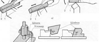
When considering how to determine the thread pitch, the features of the chosen method should be taken into account. When using a ruler it is enough:
- Measure the length of the rod on which the profile was applied. It is worth considering that by measuring the entire length of the rod, and not just part, you can determine a more accurate result.
- Count the number of turns.
- Take depth measurements to determine the main parameters of the threaded connection.
In this way, only the average can be determined. If errors were made during the cutting process, the distance between them may differ slightly.
An example of measurements looks like this:
- 20 turns are counted.
- We measure the length of the rod, for example, the indicator was 127 mm.
- We divide 20 turns by the length of the rod, the result is 6.35 mm. It corresponds to the pitch of the threads in millimeters.
To convert to inches, simply divide the calculated value in millimeters by 25.4. The result will be 0.25 or ¼ inch. If you measure yourself, there may be an error, so the result is rounded to an approximate standard value.
You can also find special templates on sale that can be used to check the features of the thread. This procedure is quite simple to perform:
- The most suitable template is selected. On sale you can find simply a huge number of special templates, which are represented by a plate with a certain profile. Such an element is not expensive; you can purchase it in various specialized stores.
- It is applied to the surface to monitor basic indicators. The template must fit without obstacles, and there should be no free space between the plate and the working surface.
If the template easily fits into the grooves, then the basic parameters of the surface can be determined.
Measuring thread pitch with a ruler and thread gauge
In addition, you can take measurements using a caliper. This tool has become widespread. The step-by-step actions are as follows:
- The depth gauge determines the height of the rod.
- The next step is to count the number of turns. This is quite difficult to do; you can use a marker to indicate the profile threads that have already been counted.
- The information obtained allows you to calculate the tangent of the angle of inclination.
It is possible to determine the indicator in question by direct measurement between adjacent vertices. It is recommended to clean the surface. Otherwise, it is almost impossible to get an accurate result.
How to distinguish metric threads from inch threads
Only craftsmen who deal with threads on a daily basis are able to distinguish metric from inch threads, or vice versa, by eye. If a non-professional tries to distinguish threads by eye, there is a very high risk of mistaking a 5/16-inch UNC bolt for a metric M8. You can determine compliance with the thread type using a thread gauge, but when such an identifier is not available, you must resort to other methods.
The easiest way to understand what type of thread is on a bolt is to use a nut with already known parameters (and vice versa). If this is not possible, then you should resort to the following actions:
- Inspect the head of the part, which may have radial lines
- If radial lines are present on the head of the fastener, this indicates the presence of an inch thread.
- The absence of radial lines confirms the use of metric threads
However, this method is not always acceptable, since fasteners with strength classes from 0 to 2 are not marked. The presence of lines and numbers on the bolt head indicates the strength of the product.
Types of thread gauges and features of determining the thread pitch on bolts and nuts
When cutting threads on workpieces, it becomes necessary to use not only taps and dies, but also a thread gauge. This tool allows you to identify thread profile parameters, eliminating future difficulties with the manufacture of second elements in the connection. The device evaluates the accuracy of the cutting performed, so craftsmen whose field of activity is related to the manufacture of threaded parts simply need to have a thread gauge. What types of thread gauges there are, and how the thread pitch is determined using this tool, you will learn about this in detail in the material.
Recommendations for working with thread gauges
When using thread gauges, you need to take into account some features. These features look like this:
- It is recommended to store the device in sealed boxes or containers to prevent mechanical stress and deformation of the instrument.
- High-precision measurement results can be obtained using only a special tool, and you should resort to using a ruler, caliper and micrometer in exceptional cases when there is no specialized device at hand
- When identifying threads, it is necessary to ensure that the workpiece remains stationary. Otherwise, this will negatively affect the quality of the measurements taken.
- Thread gauges have sharp edges, so it is important to observe safety precautions during operation
- If there are external defects on the probes of the device, then such an instrument cannot be used for making accurate measurements. Defects in the form of scratches, chips, dents, etc. will negatively affect the accuracy of the calculations performed.
On sale you can find not only metal, but also plastic thread gauges. As a rule, the body is made of plastic, and the probes are made exclusively from special grades of steel. Devices with a plastic body have a significant drawback - low strength, but at the same time they cost no more than 100 rubles.
In conclusion, it should be summarized and noted that determining the thread pitch of bolts, nuts and other fasteners is not particularly difficult if you know the algorithm and own a special tool. The obtained values after using a thread gauge allow the production of a second fastener to ensure a strong and removable connection.
Source
Safety rules when working with the device
Despite the simplicity of the tool, there are certain rules for its operation that must be strictly followed. The main provisions are as follows:
- The cleanliness of the device must be excellent, regardless of whether it is metric or inch. This will help extend its service life and avoid possible failure.
- To store the device, you need to get a strong and dense container with a hard surface. The ideal option would be a box or container.
- You cannot use other devices that are not intended for carrying out measuring manipulations instead.
- The workpiece with the markings made must be firmly fixed and in a stationary position. If this is not done, a significant measurement error may occur.
- The master, regardless of experience and skills, must wear special clothing to avoid the possibility of injury.
- It is strictly forbidden to operate a faulty product. The probes should be smooth, no scratches, chips or dents. The presence of defects will negatively affect the accuracy of the measured data and subsequent calculations.
It is worth noting that many problems arise due to the poor quality of the materials used in the manufacture of products. Long service life is guaranteed for steel structures. If you purchased an inexpensive product with a body made of plastic, expect it to fail prematurely. Plastic is not particularly durable, so with regular active use of the device, it can quickly fail.
Measurement methods
There are quite a large number of different ways to determine the thread pitch. All of them are characterized by their own specific features that need to be taken into account. Common methods include:
- Using a regular ruler.
- The use of a special tool that can be used to determine the value in question. A thread pitch meter can be purchased at a specialty store.
- A caliper is a precision instrument. It is used quite often due to its high accuracy and versatility in use.
Thread gauge
Contents: Hide Open
A thread gauge is a specialized hand-held tool for determining thread parameters, widely used as a means of monitoring cutting accuracy and the condition of threaded connection elements. Due to its simplicity and high measurement accuracy, the tool is widely used in modern metalworking and repair and assembly operations.
Thread measuring instruments. Thread measuring wires.
Active control devices.
One of the most progressive control methods is active.
Its most rational use is in conditions of mass and large-scale production. Active control devices for a certain dimensional measurement allow you to automatically change the course of the technological process and ensure the specified processing accuracy. Active control devices can be turned on at the end of the processing cycle and, based on the measurement results, issue a command for sub-adjustment of the cutting tool (they are called sub-adjusters) or check the dimensions of the product directly during processing in order to regulate the amount of movement, cutting modes and other parameters of the technological process. Active control devices that regulate the parameters of technological processes are used in computer-controlled machines.
For automatic control and adjustment, contact and non-contact devices are used. For contact action devices, the tip is in contact with the product being measured and can, when triggered, cause an error in the device. To reduce this possibility, the tips of active monitoring devices are made of carbide, diamonds, agates or other particularly hard materials.
Devices for measuring threads.
The main controlling parameters of threads are the outer middle and inner diameters, profile angle and pitch. When measuring threads, complex and element-by-element control means are used.
For comprehensive control of external metric threads, rigid limit ring gauges ( GOST 17763 - 72 and GOST 17764 - 72 ) or threaded clamps are used. Internal threads are checked with thread plug gauges ( GOST 17756 - 72 and GOST 17759 - 72 ). When using threaded plug gauges and rings, the complex meter is the pass gauge. A no-go gauge is used to measure the maximum size of the average diameter.
With element-by-element inspection, the outer diameter of the bolt can be checked by any measuring instrument used to control the diameter of shafts, and the internal diameter of the nut by any measuring instrument used to control holes.
To control the average diameter, contact or non-contact methods are used. The contact control method is based on the use of micrometer inserts or three wires.
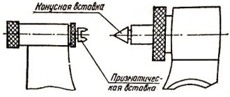
Thread micrometer inserts.
A micrometer with inserts is used to control the average diameter of triangular threads with profile angles of 60 and 55°. The measurement is made in the range from 0 to 350 mm, and for each 25 mm interval either separate micrometers or special interchangeable anvils are used. The set of inserts for the micrometer consists of two inserts (Fig. 1): a prismatic one, which is installed instead of the heel of the micrometer, and a conical one, installed in the hole of the micrometer screw.
Rice. 1. Inserts for thread micrometer.
The micrometer is equipped with five sets of inserts, which are installed in relation to the pitch of the thread being tested: 0.4 - 0.5; 0.6 - 0.8; 1 - 1.5; 1.75 - 2.5 and 3 - 4.5 mm.
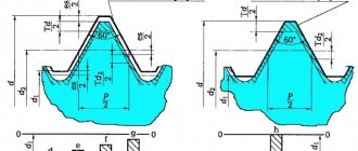
Measuring threads using the three-wire method.
When checking the average diameter, a set of three wires of the same diameter is used. During the measurement process, two wires are installed in the thread recesses on one side, and the third in the opposite recess. The size of the wires is selected according to a special table depending on the pitch and angle of the thread profile. The ideal size for wires is the diameter d = tan α /2c, where cs is the pitch, and α /2 is the profile angle of the thread being tested.
Measuring the average thread diameter.
Depending on the required accuracy when measuring with wires, micrometers or optical-mechanical devices are used, which provide more accurate readings. If the axes of the wires are located vertically during measurement, then the wires are suspended on a bracket mounted on the device used (Fig. 2). Measuring surfaces are brought to the wires and the distance between the protruding points of the three wires located in the recesses of the thread is measured, then the average diameter is determined using the formulas.
Calculation of the average thread diameter.
Medium thread diameter with profile angle 60°:
Dcp = M – 3 d + 0.866 s ,
where M is the size obtained as a result of measurement, mm;
d—wire diameter, mm;
s — pitch of the measured thread, mm.
If the profile angle is 55°, then the average diameter of the cylindrical thread:
Dcp = M – 3.165 d + 0.9605 s .
Rice. 2. Measuring the thread using three wires.
Non-contact methods of thread inspection using the average thread diameter are based on three wires, the use of measuring microscopes with goniometric eyepiece heads, and also projectors.
Indicating measuring instruments.
Monitoring the accuracy of the thread pitch and measuring the profile angle is also carried out using measuring microscopes or projectors.
Control of the average diameter of the internal thread can be carried out with indicator instruments with sliding half-plugs, indicator instruments with sliding inserts, as well as on horizontal optimeters using measuring arcs for internal measurement equipped with ball measuring tips.
At most factories, when boring holes for preliminary measurements, they use plugs and punches, as well as calipers. Installation of the cutter to remove chips to the required size is carried out along the dial of the machine's transverse support based on the readings of the caliper. When machining holes according to the 2nd and 3rd accuracy classes, this generally accepted measurement method is associated with a large amount of time spent on removing test chips, and often on unnecessary passes.
You can measure the dimensions of a number of parts during processing using an indicator device (Fig. 3), which, thanks to the special design of the stop bar 1, allows you to install indicator holder 3 4 in a convenient place, in front of the transverse slide of the caliper. When feeding the transverse slide away from you, the indicator pin rests against the protrusion of bar 1. Screw 2 protects the indicator from breakage. This device is universal; it can be used both for boring and turning. For turning, the stop bar and indicator 3 are rotated 180°.
Rice. 3. Indicating device for active control of dimensions during machining on a lathe.
Practice has shown that the use of indicators and setting rings with the nominal size of the hole being machined, as well as the use of an indicator device (Fig. 3), can reduce auxiliary time and ensure high accuracy of measurements of internal dimensions.
When processing holes, it is necessary to use the indicator to adjust the cutter to remove the first chip with an allowance of 0.1 - 0.2 mm per side, note the indicator reading and remove the first chip. After this, measure the resulting hole size with an indicator device adjusted to the setting ring that has the nominal size of the hole (when adjusting, the indicator device is set to zero).
Having measured the hole, it is determined which layer of metal needs to be removed with a cutter to obtain the final size of the hole, and using the indicator, the cutter for boring the hole is set to the finishing size. This method of measurement simplifies boring holes according to the 2nd and 3rd accuracy classes, and it is quite accessible to low-skilled workers.
For large batches of parts of small mass, it is sometimes advisable to first carry out preliminary boring of the entire batch of parts with an allowance of 0.3 - 0.5 mm per diameter and then, in one pass, using a rigid cutter, carry out finishing boring.
Considering that the cutter wears out during operation, as a result of which the size of the hole decreases, during the processing of each subsequent part, you should check the actual size of the hole of the already processed part with an indicator for internal measurements and, based on the indicator readings, adjust the indicator device taking into account the wear of the cutter.
The advantage of working with an indicator is that its readings are not affected by wear on the threads of the screw and the nut of the transverse caliper, whereas the readings on the dial depend on the degree of thread wear.
It should be noted that generally accepted methods of boring holes do not provide high accuracy. When processing a hole whose diameter is smaller than the specified one, the turner does not have an exact idea of how many hundredths of a millimeter need to be additionally removed to obtain the final size. Therefore, he is often forced to resort to additional passes, which significantly increases processing time and degrades quality.
The use of indicator devices makes it possible to work confidently and with great accuracy. The use of an indicator does not exclude the use of limiting calibers. Checking the holes with the limit gauge is mandatory during the final size control.