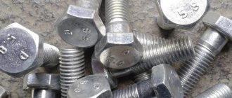
A thread is a type of cutting on the surface of fasteners with alternating projections and depressions. Several types are used and the most popular are metric and inch; in addition, there are inch pipe, screw, and trapezoidal. Now we will talk only about metric threads, since it is the most common in Russia and the CIS countries.
All fasteners - bolts, screws, self-tapping screws, self-tapping screws - use threads with a main (large) or fine pitch.
Both types are characterized by several basic parameters:
- Thread profile - the outlines of protrusions and recesses in the longitudinal section of a fastener, running along the axis of the fastener.
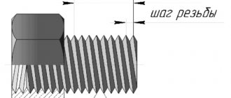
- Thread pitch is the distance between two adjacent protrusions, measured along the axis of the fastener.
- Profile angle – the value of the angle between the faces of the profile, measured in a section by a plane along the axis of the fastener.
- Outer diameter – the largest diameter of the fastener, measured at the tops of the profile.
- Thread stroke is the value of the longitudinal movement of the fastener per turn.
GOST 8724-81 determines that a step from 1 to 68 mm is a large step, higher than 68 mm is only a small step. Also, it should be noted that the fine thread pitch can be different for the same rod diameter, while the large thread pitch has only one value.
Metric threads have a profile of an isosceles triangle with an angle of 60°, which is also called a fastening thread. Since all thread parameters - diameter and pitch - are indicated in millimeters, it is called “metric”. It is used for application on both external and internal surfaces of fasteners, most often cylindrical in shape. There are several standards for metric threads. For example, in Europe and the USA, ISO metric threads are more often used. Metric is designated by the letter “M” indicating the value of the outer diameter of the thread and, after the multiplication sign “×”, the designation of the thread pitch (for example, M12 × 0.75).
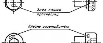
Thread length: 8.8, 10.9 high strength nut bolts
The thread length is the length of the surface area on which the thread is formed, including the thread runout and chamfer. As a rule, only the full profile thread length is indicated on the drawings.
It is possible to produce bolts with long threads: standard, full, without thread.
Thread length:
| Standard | The standard thread length of bolts of the same size group is the same regardless of the length of the bolts. When designating bolt parameters, the standard thread length is not indicated. Standard threads are widely used in fasteners |
| Full | Full thread is called a thread up to the bolt head. When designating bolt parameters, it is additionally used when the fastener or bolt is screwed into the body; when installing clamps for plumbing equipment; when tightening materials of different thicknesses. |
The calculation of thread parameters is based on the nominal thread diameter, thread pitch and internal thread diameter:
| D… Nominal outer diameter of internal thread (nut) d… Nominal outer diameter of male thread (bolt) D/d Nominal thread diameter D2/d2 Nominal mean thread diameter D1/d3 Nominal internal thread diameter )> Thread pitch |
The value of metric thread diameters is calculated using the formulas:
D2 (d2) = D(d) - 0.6495P D1 (d1) = D(d) - 1.0825P
External thread (bolt) dimensions are measured with gauges, micrometers or optical gauges, while internal thread (nut) dimensions are measured with cylindrical gauges.
Selecting parameters
How to choose the right hardware, with what parameters? The main thread pitch for hardware products used in the Russian Federation is metric coarse. Almost all construction fasteners have a large thread pitch. It is sold everywhere in hardware stores and companies and is recommended for use. Threaded hardware with fine pitches are mainly used at fastening points subject to vibration and dynamic alternating loads. For example, fine pitch nuts and bolts secure the wheel rims to the hub. Fasteners with fine threads are in high demand in the automotive, ship, machine tool and aircraft industries.
Basic thread parameters taken into account when connecting parts:
Thread tolerance
Tolerances are established for two thread diameters - the average diameter and the diameter of the projections (outer diameter of the external thread and internal diameter of the internal thread).
The mean thread diameter tolerance determines the permissible degree of deviation of the nominal mean diameter of the external (d2) and internal threads (D2).
The tab diameter tolerance specifies the allowable amount of variation between the nominal outside diameter (d) of an externally threaded fastener (e.g., bolts, screws) and the nominal inside diameter (D) of an internally threaded fastener (e.g., a nut).
The mean and shoulder diameter tolerance values are always negative for male fasteners and positive for female fasteners.
A positive tolerance for internal threads and a negative tolerance for external threads allows you to leave the necessary tolerance for possible subsequent processing.
| 0 - zero mark (h/H) - Nominal diameter. +/- - positive/negative tolerance zones. e/g/G — tolerance position relative to 0 (h/H) 6/7/8 - degree of tolerance accuracy * - standard bolt/nut tolerance size Es/ei - maximum size of the tolerance zone boundary Ei/es - minimum size of the tolerance limit |
Tolerance field
The distance between the maximum and minimum value of the set limit (field size es-ei/EI-ES) determines the tolerance range. The thread tolerance field is formed by a combination of the tolerance fields of the average diameter and the diameter of the protrusions.
The position of the thread diameter tolerance field is determined by the main deviation (upper for external threads and lower for internal threads) and is indicated by a letter of the Latin alphabet, lowercase for external threads and uppercase for internal threads.
The designation of the tolerance field of an individual thread diameter consists of a number indicating the degree of accuracy and a letter indicating the main deviation. For example, 4h; 6g; 6H.
The designation of the thread tolerance field consists of the designation of the tolerance field of the average diameter placed in the first place, and the designation of the tolerance field of the diameter of the protrusions.
7g 6g (tolerance range d2 and d).
If the designation of the tolerance field for the diameters of the protrusions coincides with the designation of the field for the average diameter, then it is not repeated in the designation of the thread tolerance field.
Recommended tolerance ranges for make-up length N (before applying anti-corrosion coating) for fasteners with DIN, ISO, DIN ISO, DIN EN ISO, GOST standards:
| Accuracy class: | Average | Rude | ||
| Thread | Nominal outer diameter of external thread (screw, bolt) | Nominal outside diameter of internal thread(nut) | Nominal outer diameter of external thread (screw, bolt) | Nominal outside diameter of internal thread(nut) |
| Without cover | 6g | 6H | 8g | 7H |
| Thin electroplated coating | ||||
| Large sizes (uncoated) | 6e | 6G | 8e | 7G |
| Thick electroplated coating | ||||
| Product accuracy class: | A, B | C | ||
| GOST | 7798-70, 7805-70 | 5915-70, 5927-70 | 15589-70 | |
| DIN | 931, 933 | 934 | 558, 601 | 555 |
| ISO | 4014, 4017 | 4032 | 4018, 4016 | 4034 |
Basic parameters of a threaded connection
The industry offers various sizes and types of metric threads that meet certain technical parameters:
- Outer diameter - the distance between the vertices of the threaded edges located opposite each other.
- Inner diameter is the distance between the opposite cavities of a threaded notch.
- Thread pitch is the distance between two adjacent thread tips.
- Profile is a parameter indicating the height of the coil. Is the difference between the outer and inner diameter of the thread.
- The profile angle at the apex is the angle between the side surfaces of the notches; in a metric thread, it is equal to 60°, so the profile is an equilateral triangle. Less common are trapezoidal, rectangular, and hemispherical threads.
- The shape of the contour can be cylindrical or cone-shaped.
The correspondence of the parameters of different types of threads is indicated in GOST 8724-2002, metric threads are designated by the letter M, for example, a stud with a diameter of 6 mm is designated M6. The thread pitch can be basic (standard) or fine. It is important to know that for one diameter a single main pitch and several minor thread types are used.
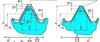
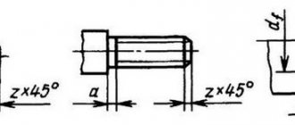
Metric thread. Dimensions.
The figures show the dimensions of threads with diameters of 5... 64 mm, used in strength calculations.
The choice of thread pitch depends on the required strength of the screw rod weakened by the thread, self-braking conditions or the need for fine adjustment.
To facilitate calculations, the design diameter of the screw, the design cross-sectional area of the screw and the helix angle at the average thread diameter are additionally given.
Notes:
- Large thread pitches are highlighted in bold.
- See thread designations above.
- The design diameter dр of the screw is determined by the dependence, where d3 is the internal diameter of the bolt.
- The design cross-sectional area Ap is determined by the dependence.
- The thread helix angle ψ is determined for the average diameter (d2) of the thread according to the dependence
Related Pages
- Cylindrical threads
- Tapered threads
- Runs, undercuts, grooves and chamfers according to GOST 10549
- Thread persistent
- Trapezoidal thread
- Mechanical properties of bolts, screws, studs, nuts.
- Symbols of fasteners according to GOST 1759.0 (ST SEV 4203)
- General Purpose Hex Head Bolts
- General purpose screws
- Captive screws
- Set screws
- Special purpose bolts and screws
- Self-tapping screws for metal and plastics
- Locking the nut against the bolt with additional elements
- Locking the nuts relative to the body
- Locking the nut relative to the bolt due to additional friction, welding and plastic deformation
- Locking bolts. Preventing screws and nuts from being lost
- Locking screws
- Flange connection parts
- Flange connections for pipes and cylinder heads
- Flange connections for metal structure pipes
- Application examples for set screws
- Terminal connections
- Friction screw clamps
- Ties and stops
- Fastening machines to bases
screwing
The force of interaction between the inclined plane and the slider during relative motion is the resultant F
normal force and friction force.
Consequently, this force is inclined to the normal n – n
at the friction angle
j
.
As a result of decomposition of the resultant force F
into circumferential
Ft
and axial
Fо
, we obtain
, (12.3)
where j
- friction angle,
f ' -
reduced coefficient of friction in the thread.
Moment of Tzav
screwing of a nut or screw with a head is represented by the sum of the moment
Tr
in the thread and the moment
TT
at the end of the nut or screw head.
Torque Tr
, which must be applied when screwing the nut (thread torque), has the form
.
(12.4)
The supporting surface of the nut and the screw head is an annular one with an outer diameter equal to the wrench size of the nut a
and an internal diameter equal to the diameter of the screw hole
d
. Then the average diameter of the annular surface will be .
Let us represent the moment at the end of the nut by the product
. (12.5)
We write down the screwing torque taking into account dependencies (12.4) and (12.5)
. (12.6)
For standard metric threads, average y
=
2о30'; j = 8о40'; dcp = 1.4 × d ; d2 =
0.9 × d . Since the tightening torque is equal to the torque on the key
. (12.7)
Substituting (12.7) into (12.6), we obtain the relationship between the axial force and the force on the key.
Thus, the gain in strength is quite significant. Therefore, when retightening bolts and studs with a diameter of less than 12 mm, there is a danger of stripping the threads and destroying their rods. For example, an M6 bolt from St3 is destroyed by a force on the handle of a standard wrench of 90...100 N. Therefore, in critical cases, special wrenches with a controlled tightening torque are used.
Thread efficiency is defined as the ratio of useful work on the screw to the work expended on the wrench when turning through an arbitrary angle. For simplicity and generality of the conclusion, it is convenient to consider rotation through a small angle d g
, in which the forces can be considered constant even when the fastening thread is tightened. Then the efficiency of the thread itself without taking into account friction at the end will be
, (12.8)
where dh
is
the axial displacement corresponding to rotation through the angle
d g ,
.
Substituting into the resulting dependence (12.9) the value of the moment TP
on the thread (12.4), we get
. (12.9)
For elevation angle y
=
2о30'
and friction coefficient
f = 0.15 ( j = 8о40')
efficiency is
h
= 0.22.
The efficiency of the screw, taking into account friction at the end of the nut, will take the form
. (12.10)
When unscrewing, the torque is obtained, as when screwing, in this case only the sign of the helix angle changes to the opposite
. (12.11)
The self-braking condition is as follows
, , . (12.12)
For normal metric threads with lead angle y
=
2о30'
self-braking, even in the absence of friction at the end of the nut, occurs at
j > 2.30',
i.e., at a friction coefficient
f > 0.045.
If there is friction at the end of the nut, self-braking will occur at a friction coefficient
f > 0.02.
Thus, under static loads there are large reserves of tightening reliability. However, under conditions of vibration loads, the coefficient and angle of friction sharply decrease, which can lead to loosening of the thread, to avoid which special locking devices are used.
Protecting threaded connections from self-unscrewing
. All fastening threads satisfy the self-locking condition even without taking into account additional friction at the end of the nut or screw head. However, as operating experience shows, under variable or shock loads, loosening of the threads is observed. Therefore, special locking means are required.
The following types of locking are used:
– special elements – cotter pins, washers;
– plastic deformation or welding after tightening.
Interaction between screw and nut
. The distribution of axial force between the threads of the screw and nut would be uniform if the thread were manufactured absolutely precisely and the compliance of the thread was significantly higher than the compliance of the screw and nut. In reality, neither one nor the other condition holds.
Read also: Bolt thread in the drawing
The problem of distributing forces between the threads of a screw and a nut is statically indeterminate. I solved this problem for a nut with 10 turns. The first, most loaded turn accounts for up to 1/3 of the total load, and the last, 10th turn of the nut thread accounts for less than 1/100 of the total force. Deformations in
thread due to profile errors, contact deformations and local plastic deformations somewhat reduce the load on the 1st turn of the nut thread.
With such a sharp unevenness in the loading of the turns, there is no need to make the height of the nut greater than 10 thread pitches.
Today, various threaded connections are often used in mechanical engineering. Carving is a complex technological process requiring certain skills and abilities. To cut threads, you must be able to set up a machine, select, sharpen and install cutting tools, and of course, know how to use thread measuring instruments. Currently, metric threads (have a triangular profile) are often used. Let's start in order and first look at the general concepts: