So, you have a bolt or nut with unknown thread parameters, and there is no measuring tool at hand other than a ruler. Let us immediately warn you that using a ruler can only get a rough result, so if you are going to regularly take such measurements, it is better to purchase a thread gauge or caliper.
Thread pitch - distance between turns
Threads are made according to approved standards, which made it possible to unify all threaded connections. The pitch of a metric thread is the distance between adjacent peaks or valleys of a threaded profile. It is this distance that we have to measure.
Measuring the internal diameter of a thread
The internal diameter of the cutting is controlled by a measuring device with pointed legs - calipers.
To organize computational work, you need to install the tool on a template part using a threaded gauge, and then make a comparison with the original internal diameter of the threaded connections. The caliper must be at an angle relative to the axis being measured. Also, measuring internal threads can be carried out with instruments for cylindrical threads. This is because the inside diameter has a smooth surface, which is ideal for the shape of the tips used in these instruments. Verification of the obtained measurements is done using plug gauges.
Measurements during the design and manufacture of threaded connections
The “bolt-nut” type connection is one of the most common in mechanics. When designing and manufacturing structures, the problem of how to measure a bolt with a caliper is often difficult.
Before starting work, it is worth remembering that the main dimensions of a bolt/nut are the length of the product and the diameter of the thread. A standard bolt of any design does not require such measurements. It’s a different matter when the bolt is made at home, or you need to measure the fastener without dismantling the connection. The following situations are possible here:
- Between the head and the opposite end of the rod there is a plane or part/plate, the dimensions of which do not allow the insertion of the measuring jaws of a caliper. In this case, using the main measuring scale and a depth gauge (sometimes called a “Columbic”), the height of the head, the thickness of the washer (if any), the thickness of the intermediate element and the height of the part protruding from the opposite side of the joint are determined. The obtained result is added up, and then, according to the tables of correspondence between the lengths of the rod and the “turnkey” dimensions that the bolt has, the standard size of the fastener is determined.
Measuring internal threads and imprinting threads
Thread pitch measurement
Measurement methods
There are quite a large number of different ways to determine the thread pitch. All of them are characterized by their own specific features that need to be taken into account. Common methods include:
- Using a regular ruler.
- The use of a special tool that can be used to determine the value in question. A thread pitch meter can be purchased at a specialty store.
- A caliper is a precision instrument. It is used quite often due to its high accuracy and versatility in use.
All of the above methods allow you to obtain fairly accurate data. The easiest way to take measurements is to use a thread-finding tool, but you can get by with a regular caliper.
GOST and the need for unification
For a long time, manufacturers performed theoretical calculations of thread pitch using their own methods and manufactured fasteners using their own technologies. With this approach, connectors from different brands often turned out to be incompatible or did not provide suitable joint quality, which often caused problems for users.
Particular difficulties arose during the assembly of machines, apparatus and other component equipment. Literally each element had to be marked separately so that later it could be placed correctly. Banal preventive cleaning of tools or machines, parts of which were supplied by two or more factories, turned into real torture.
Therefore, from the beginning of the 20th century, the issue of standardization became seriously concerned. The matter was approached with the utmost seriousness, taking into account even the experience of the 12th century, or rather the practice-tested formula stating that the distance between adjacent turns should be equal to 20% of the diameter of the rod. Naturally, they took into account that in those distant times the fasteners were made of wood, and only 20 years later they began to tighten the most loaded points with studs and protect them with nuts machined from a single piece of especially strong rock. Today, completely different materials are relevant, which have completely different requirements.
Food for thought
The first path to standardization began to be paved precisely in Russia: at the Tula plant they began to work according to Nikita Demidov’s drawings, and check the results using the calibers he proposed. This made it possible to control the accuracy of casting and execution of individual parts.
Yes, the famous industrialist did not think specifically about the thread pitch (how to measure it or find the optimal one), but sought to unify production as a whole. And he achieved his goal: in 1787, a commission under the tsarist army purchased 500 domestic guns and the same number of English ones. The inspectors disassembled each of them, arranged the elements according to their functional purpose and thoroughly mixed each group, after which they tried to assemble it. In the case of the Russian models, this was possible - even though they required grinding in, they eventually passed the zeroing - but the pride of the British craftsmen remained a pile of useless iron.
This was the impetus for the following events:
Each regiment created a platoon responsible for servicing weapons, and it regularly received consumables marked with notches to replace small items that had failed.
In France, in 1790, they approved the first pan-European basic system of measures, adopting m and its “derivatives” – cm and mm – as a unit of length, which is still used today; England, by the way, remained with its inches and feet.
In the USSR, the first GOST for the compounds in question was introduced in 1924.
Concept of thread pitch
Threads are used to connect a wide variety of products. To determine the bolt thread, you need to consider the distance between the same sides of the profile. The features of this concept include the following points:
- To determine the main parameters, a measurement is required.
- An inaccurate result can be determined by using a ruler.
- To increase the accuracy of measurements, you need to analyze several threads. That is why, depending on the length of the threaded surface, an analysis of 10 to 20 turns is carried out.
- It is recommended to take measurements in millimeters. In some cases the number is converted to inches.
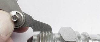
The distance between the depressions can be measured using a special tool. The thread gauge is represented by a combination of special steel plates that have special cutouts. Various values are applied to the surface.
Determining diameter at home
The need to find out the exact diameter arises only in two cases - there is no marking on the outside or the absence of conditionally control items with a known cross-section (fittings, adapters). By marking you can determine all the parameters - purpose, material of manufacture, wall thickness. With the help of fittings and adapters, they find out whether a particular pipe is suitable for water supply and heating.
You can take measurements at home using a ruler (tape measure), caliper, or micrometer. The accuracy of the results obtained depends on this. You can use other means - thread, a box of matches or any object whose dimensions are known and do not exceed the cross-section of the pipeline.
How to measure using a caliper?
This is a universal measuring device with which you can find out all the dimensions of the pipeline.
In addition to the maximum and minimum values, they differ in how the results are taken:
- In vernier scales (SC), millimeters are marked on the main scale, and fractions of mm on the auxiliary scale. When the rod moves, the pointer stops at a certain value.
- Dial (ShTsK) are needed for more accurate measurements. Fractions of mm are shown by a circular scale connected to the rod by a gear transmission. In digital (DCC) the value is displayed on the LCD screen.
How to measure the internal diameter of pipes using a caliper:
- Clean the inner surface from dirt and dust.
- Move the rod jaws to the zero position.
- Install them into the hole.
- Spread the sponges all the way, trying to get the maximum value.
To measure the outer section, you need to spread the jaws of the caliper and place them between the pipeline. To get an accurate result, you need to apply a little pressure. Repeat the procedure 2-3 times.
Before starting work, it is recommended to check the accuracy of the caliper readings by taking the dimensions of a standard object with known dimensions or cross-section.
We measure with a micrometer
A pipe micrometer is convenient for quickly taking readings of external dimensions. If you need to know the internal diameter, you should measure the wall thickness. Unlike calipers, most micrometer models give more accurate results, the average error is 3-5 microns.
Micrometer Applications
The procedure for carrying out internal measurements:
- Place the pipe between the heel and the spindle and take readings.
- Also find out the wall thickness.
- Subtract 2 thickness readings from the external dimensions.
The disadvantage of the device is the maximum size limitation. To increase accuracy, special attachments are used. When performing calculations, it is necessary to add the dimensions of the nozzles to the obtained indicators.
Laser sensors
The operating principle of laser sensors is based on scanning a surface with a laser beam. The rate at which radiation returns to the photodetector determines the distance traveled. To increase accuracy, the working head rotates, which makes it possible to take a large number of measurements per second. Such devices are used only in mass production, where control of the uniformity of wall thickness at a certain length is important.
Operating principle of pipe laser sensors:
- The measuring part of the device is placed inside the cavity.
- Fixation using roller clamps.
- Several series of measurements on different sections of the highway.
- Data reconciliation.
The advantage of the method is maximum accuracy and the ability to take measurements at various depths remotely. The disadvantage is expensive equipment. It is used only during the manufacturing process or when large quantities of pipes are used, where accuracy is important.
Measuring pipe diameter with a laser sensorHow to measure a nut
Most nuts have metric threads. Measuring the thread diameter will require a little more steps than in other cases. If possible, it is recommended to check the size of the bolt or screw used for it rather than the nut itself. This way you can achieve a more accurate result.
The value obtained after measuring the internal thread is an indicator of the internal diameter din.
In order to accurately determine the diameter of the metric thread of the hardware, you will need to find out the correspondence between din and the outer diameter of the bolt used. This is done using a special table.
Accuracy is controlled through the use of certain pass-fail gauges. One part should connect well with the nut, the second part, on the contrary, should not.
The nuts differ in appearance, and it is easy to determine upon detailed inspection. To find out the standard of the fastener, you may need to measure the height of the hardware, since there are high, low, extra high and other options.
Turnkey dimensions are also used to classify hex nuts. This is explained by the fact that hardware also differs in its types.
To accurately measure the thread pitch, it is possible to use the method considered in the case of a bolt. You will need a thread gauge or you will have to count the number of turns at the required interval.
Determining the dimensions of inch nuts
To check the thread dimensions of an inch nut, you need to examine the threads of the bolt or other hardware used with it. If you don’t have a suitable one at hand, but have information about the presence of an inch thread, then use the appropriate thread gauge. Do not forget to divide the resulting value by 25.4 mm.
Determining washer dimensions
For washers, a short designation in the form D is used, which stands for the diameter of the metric thread of the hardware used for the fastener.
To accurately measure indicators, a ruler or caliper is suitable. The result is a value that is slightly higher than the figure in the notation. This is explained by the fact that free movement is required during installation, which requires a small gap.
So, you have a bolt or nut with unknown thread parameters, and there is no measuring tool at hand other than a ruler. Let us immediately warn you that using a ruler can only get a rough result, so if you are going to regularly take such measurements, it is better to purchase a thread gauge or caliper.
Screen thread gauge for Android
Even an ordinary smartphone can replace a thread gauge in everyday life. To do this, you need to download the Android application “Thread pitch meter. Thread gauge" from the developers of the Smart Tools toolkit. Simply apply a screw to the screen, look for the exact match of the turns and find out the pitch. Various types of threads are available in the mobile application: metric, inch and pipe standards.
Screen thread gauge for Android
As for inch and metric threads, there are approximate matches. But it’s hard to imagine how you would try to screw a 1/2″-20 UNF bolt into an M12x1.25 hole. As for the M14x1.25 thread, yes, everything is correct.
Evgeniy Guryevich, 1) On threading tools, as well as in reference tables, it is indeed customary not to use the “X” sign. But not in the designation of LARGE, but MAIN THREADS. In practice, many foreign manufacturers still provide full markings of the thread size, for example 12x1.75, both on the tool and on the packaging with fasteners. Soviet and Russian companies producing cutting tools also often “sin” with this. You don’t have to look far for examples - this is the former Sestroretsk tool plant, the German company Reyher. This is done mainly so that the user does not have doubts about the correct choice of the product. It's no secret that most salespeople in stores, mechanics in factories, and sometimes even designers don't know (don't remember) the pitch table for not only small threads, but also major threads. In these cases, detailed size markings help.
Measuring thread pitch without a thread gauge
Parts with external thread
Often the need to determine the thread pitch arises sporadically, at one time. And, of course, in such a situation there is no thread gauge at hand, and it makes no sense to buy one for one-time measurements. It will be useful to learn how to measure the thread pitch with a ruler or caliper. These measuring tools make it quite easy to determine the desired parameter.
The easiest way is to measure the threads of a bolt or other externally threaded part. When measuring a metric thread, it is recommended that you first attach the ruler to the threaded part and try to align the millimeter divisions of its scale with the tops of the ridges of the threaded profile. If they coincide, then the step is 1 mm. Otherwise, you will have to carry out slightly more complex measurements.
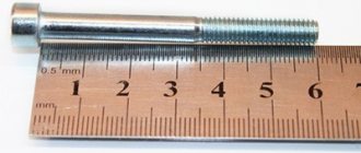
To determine the thread pitch, you need to count the number of turns on a section of a rod of a certain length, for example, 10 mm or 20 mm. To obtain a more accurate result, it is recommended to take measurements on a 20 mm area. The required length is measured by applying a ruler to the bolt shaft, or using a caliper. It would be more accurate to measure the bolt thread pitch with a caliper. In the measured area, count the number of turns. After this, the length of the section must be divided by the resulting number of turns minus one turn. As a result, we obtain the value of the thread pitch.
When determining the pitch of an inch cutting, it is necessary to measure the length of the rod equal to one inch (25.4 mm). For accurate measurements, it is better to use a ruler or caliper with an inch scale. The number of turns in this area will be the thread pitch. If the length of the threaded section is less than one inch, then you need to determine the number of turns in a section of half an inch (12.7 mm), and then multiply the result by 2.
Internally threaded parts
There are two ways to measure the thread of a nut or other internally threaded part without a thread gauge. The first method involves selecting an exactly suitable counter bolt and then measuring its thread pitch. If you can’t find the counter bolt, then you need to use a strip of paper (this is method No. 2).
It should be pressed against the thread so that an imprint of the profile remains on the paper. You can improve the visibility of marks by tracing the edges with a marker. After this, on paper you need to mark the distance between the extreme marks with a ruler and count the number of turns. Then the resulting distance is divided by the number of turns minus one turn. Instead of measuring paper using this method, you can use a pencil, match or other soft wood product of a suitable size, which is pressed against the thread.
Rules for using vernier calipers
In order for a measuring instrument to serve faithfully for many years, it is necessary to follow simple rules for its operation and storage. First of all, mechanical damage that may occur as a result of a fall or force should be avoided. In addition, during the process of measuring parts, the jaws of the caliper must not be allowed to skew. To prevent this from happening, they must be fixed in a certain position on the part being measured using a locking screw.
The device should only be stored in a soft case or hard case. The second option is preferable, as it can provide protection from accidental deformations. The place for storing the caliper must be chosen in such a way that sawdust from various materials, dust, water, chemical mixtures, etc. do not get there. Plus, the threat of heavy objects falling onto the tool must be eliminated.
After each use of the caliper, it must be thoroughly wiped with a clean, soft cloth.
Naturally, we should not forget about observing safety rules when operating this device. At first glance, it does not pose any threat to health, but this is not entirely true. The fact is that the ends of the jaws for measuring internal dimensions are quite sharp, so you can easily get hurt if handled carelessly. Otherwise, the tool is completely safe.
09 November 2022, 11:20 1078
The instructions, to a greater extent, concern the determination of the sizes of metric bolts, screws and studs (hereinafter simply bolt). The fundamental dimensional characteristics of a bolt are diameter, thread pitch and length.
Bolt diameter
The exact diameter of a bolt, like any other object, is measured with a caliper or micrometer. However, there are situations when special measuring instruments are not at hand. In this case, you can measure the outer diameter of the bolt using a measuring tape.
Wrap the measure around the bolt shaft one turn and mark the connection point on the scale. This is how we found out the circumference of the bolt. We reduce the result by 1-2 mm to eliminate the influence of the thickness of the measure on the calculations.
Knowing the circumference, we can easily calculate the diameter using a simple geometric formula. To do this, divide the circumference by Pi, equal to 3.14. Since most car bolts have standard diameters, even taking into account errors in measurements, the result will be close to standard sizes. Standard diameters of bolts used in cars: 5, 6, 7, 8, 10, 12, 14, 16, etc.
It is fair to note that this method is not suitable for measurements where special accuracy is required. For example, the driven part of a wheel stud, where every tenth of a millimeter is important, is measured only with a caliper or micrometer.
Bolt thread pitch
Another important bolt parameter is the thread pitch. Thread pitch is the distance between two adjacent turns. The thread pitch is measured by a pedometer. However, just like a caliper, there may not be a pedometer. Then calculate the distance between the turns using a ruler
To do this, count 15-20 thread turns (the more turns, the more accurate the result) and measure the distance between the outer turns with a ruler. By dividing the length of the counted turns by the number of turns, we obtain the distance between the turns, i.e. the thread pitch.
The thread pitch of a car bolt is a standardized value and is closely related to the diameter. Knowing the bolt diameter and the calculated thread pitch, we can easily determine the exact thread pitch using the following table.
Accuracy classes and marking rules
A thread belonging to the inch type, as indicated by GOST, can correspond to one of three accuracy classes - 1, 2 and 3. Next to the number indicating the accuracy class, put the letters “A” (external) or “B” (internal). The full designations of thread accuracy classes, depending on its type, look like 1A, 2A and 3A (for external) and 1B, 2B and 3B (for internal). It should be borne in mind that class 1 corresponds to the coarsest threads, and class 3 corresponds to the most precise threads, the dimensions of which are subject to very stringent requirements.
Maximum size deviations according to GOST
To understand what parameters a specific threaded element corresponds to, it is enough to understand the designation of the thread that is applied to it. The designation in question is used by many foreign manufacturers who work according to American standards relating to elements of threaded connections.
An example of a symbol for an inch thread
This marking contains the following information about the thread:
- nominal size (outer diameter) – first digits;
- number of turns per inch of length;
- group;
- accuracy class.
Geometric parameters
Let's consider the geometric parameters that characterize the main elements of metric threads.
The nominal thread diameter is designated by the letters D and d. In this case, the letter D refers to the nominal diameter of the external thread, and the letter d refers to a similar parameter of the internal thread. The average diameter of the thread, depending on its external or internal location, is designated by the letters D2 and d2. The internal diameter of the thread, depending on its external or internal location, is designated D1 and d1. The inside diameter of the bolt is used to calculate the stresses created in the structure of such a fastener. The thread pitch characterizes the distance between the crests or valleys of adjacent threaded turns. For a threaded element of the same diameter, a basic pitch is distinguished, as well as a thread pitch with reduced geometric parameters
The letter P is used to denote this important characteristic. The thread lead is the distance between the crests or valleys of adjacent turns formed by the same helical surface. The progress of the thread, which is created by one screw surface (single-start), is equal to its pitch
In addition, the value to which the thread stroke corresponds characterizes the amount of linear movement of the threaded element performed by it per revolution. A parameter such as the height of the triangle that forms the profile of the threaded elements is designated by the letter H.
Metric thread diameters (mm)
Complete table of metric threads according to GOST 24705-2004
GOST 8724 This standard contains requirements for the parameters of the thread pitch and its diameter. GOST 8724, the current version of which came into force in 2004, is an analogue of the international standard ISO 261-98. The requirements of the latter apply to metric threads with a diameter of 1 to 300 mm. Compared to this document, GOST 8724 is valid for a wider range of diameters (0.25–600 mm). At the moment, the current edition of GOST 8724 2002, which came into force in 2004 instead of GOST 8724 81. It should be borne in mind that GOST 8724 regulates certain parameters of metric threads, the requirements for which are also specified by other thread standards. The convenience of using GOST 8724 2002 (as well as other similar documents) is that all the information in it is contained in tables, which include metric threads with diameters within the above range. Both left-handed and right-handed metric threads must meet the requirements of this standard.
GOST 24705 2004
This standard stipulates what basic dimensions a metric thread should have. GOST 24705 2004 applies to all threads, the requirements for which are regulated by GOST 8724 2002, as well as GOST 9150 2002.
GOST 9150
This is a regulatory document that specifies the requirements for the metric thread profile. GOST 9150, in particular, contains data on what geometric parameters the main threaded profile of various standard sizes must correspond to. The requirements of GOST 9150, developed in 2002, as well as the two previous standards, apply to metric threads, the turns of which rise from the left upward (right-handed type), and to those whose helical line rises to the left (left-handed type). The provisions of this regulatory document closely echo the requirements given by GOST 16093 (as well as GOSTs 24705 and 8724).
GOST 16093
This standard specifies the tolerance requirements for metric threads. In addition, GOST 16093 prescribes how metric type threads should be designated. GOST 16093 in its latest edition, which came into force in 2005, includes the provisions of the international standards ISO 965-1 and ISO 965-3. Both left-hand and right-hand threads fall under the requirements of such a regulatory document as GOST 16093.
Accuracy classes and marking rules
A thread belonging to the inch type, as indicated by GOST, can correspond to one of three accuracy classes - 1, 2 and 3. Next to the number indicating the accuracy class, put the letters “A” (external) or “B” (internal). The full designations of thread accuracy classes, depending on its type, look like 1A, 2A and 3A (for external) and 1B, 2B and 3B (for internal). It should be borne in mind that class 1 corresponds to the coarsest threads, and class 3 corresponds to the most precise threads, the dimensions of which are subject to very stringent requirements.
Maximum size deviations according to GOST
To understand what parameters a specific threaded element corresponds to, it is enough to understand the designation of the thread that is applied to it. The designation in question is used by many foreign manufacturers who work according to American standards relating to elements of threaded connections.
An example of a symbol for an inch thread
This marking contains the following information about the thread:
- nominal size (outer diameter) – first digits;
- number of turns per inch of length;
- group;
- accuracy class.
If you have a question, how to determine the type and size of thread Connecting fittings for pipes and hoses
connections use the table below.
Please note the following:
- connections with inch threads are highlighted in color
- next to the inch step size in tpi the step size in mm is indicated
- connections with external tapered threads usually do not have a threaded groove
- BSPT and NPT conical fittings are very similar, but BSPT has a mark on the hexagon
An important note - situations are quite possible when the inch and metric pitches are very close in size (this is possible on JIC connections).
Read also: Scraper conveyor operating principle
In this case, it is possible to confuse the inch thread. American cylindrical inch thread UNF (Unified Thread Standard)
UNC UNF and metric threads.
Threaded fasteners are one of the most popular for attaching parts, assembling products, equipment, and structures. There is no industry where it is not used. There are many thread characteristics: pitch, tolerance range, number of starts, nominal diameter, profile type and others. One of these is units of measurement, inches or millimeters.
There is often a situation when it is necessary to replace a bolt, pin or screw, but the fastener purchased for maximum similarity “by eye” is not screwed into the mounting hole. One of the reasons is an attempt to screw a fastener with an external inch thread into a hole with a metric thread. Or vice versa. This situation often arises when replacing fasteners on products or equipment manufactured in the UK, USA, Japan, or Australia. There, inch threads have priority.
How to distinguish an inch thread from a metric thread? There are two main ways - by measuring the pitch and diameter or using a special tool.
Measurement
Fastener thread markings are done differently in metric and inch systems. In metric, this is an indication of the thread pitch (the distance between adjacent threads) in millimeters, while in inch it is the number of threads per inch.
Determining the type and size of fastener thread comes down to the following operations. Use a caliper to measure the diameter. Then, using an inch ruler or caliper, measure the number of threads in one inch and the thread pitch. You can also use a regular ruler with measured 2.54 mm (1 inch = 2.54 mm). The metric thread pitch on small fasteners can be found by measuring the distance between 10 turns and dividing the resulting value by 10. The resulting values should be compared with the table below. The maximum match in diameter, number of turns, pitch indicates the size and type of thread. It should be noted that there are many different types of inch threads. The table shows the most common ones in the diameter range from 8 mm to 64 mm.
You can also use a thread gauge to measure threads. This is its direct purpose. A thread gauge is a set of plates with protruding teeth for a specific thread, united on a single axis. The thread size is engraved or permanently inked on the plate itself. Checking the thread is done by applying plates that are closest in size to the thread. If there is a complete match, without gaps, the thread can be considered defined, and its size can be viewed on the thread gauge plate. Thread gauges are produced separately for metric, inch threads or both types.
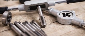
What is a thread gauge and its purpose?
First, let's find out what a thread is. A thread is a spiral that has a constant pitch over its entire area. The spiral is cut using special tools on the surface of cylindrical and conical products. This spiral is also called cutting, through which a detachable connection of parts is ensured. To obtain a spiral on a product, not only the cutting method is used, but also rolling
When working with threads, it is important to have a thread gauge and be able to use it correctly
The tool in question is similar to feeler gauges for setting thermal gaps between valves on car engines. However, such similarity is manifested only in the external design, and what a thread gauge is remains to be understood in detail. A thread gauge is a small device, the price of which does not exceed 200-300 rubles, consisting of a set of probes with teeth. It is due to the presence of teeth on the plates that this device differs from a feeler gauge for measuring the distance between valves.
Plates with toothed probes are attached to the tool body, and they are made of steel alloys. Each probe is equipped with a unique tooth shape, differing in such parameters as pitch, thickness and direction of rotation. The main purpose of the device is to measure thread pitch on various parts. It is due to this purpose that this instrument belongs to the category of measuring instruments. Moreover, this tool can be used to determine the thread pitch, both external and internal, which is achieved due to the presence of a ground surface.
There is a corresponding marking on the body of the instrument, which is presented as “D55” and “M60”. Few people know what these letters and numbers stand for. However, you need to understand this even before you learn to use a thread gauge. The marking “M60” indicates that this device is intended for measuring metric threads, and “D55” - for identifying inch threads. The digital designation indicates the angle between the vertices, that is, on a metric thread it is 60 degrees, and on an inch thread it is 55 degrees.
A digital designation is also present on the front surface of each toothed comb. The indicated values correspond to a specific thread pitch, which simplifies the identification process. For the manufacture of devices, manufacturers use the following grades of tool steel:
- U7
- 8HF
- ХВ4
These types of steels are distinguished by such advantages as a low coefficient of thermal expansion, as well as a reduced hardenability index (the ability of steel to accept hardening). It is due to these advantages that thread gauges can be used over a wide temperature range. The production of measuring instruments occurs in compliance with established standards. The production of tools is standardized to GOST 5950-85.
The combs have a special design, which allows, when taking thread measurements, not only to correctly set the pitch, but also the degree of filling of the profile with the determination of the number of threads. It is especially important to determine the number of threads or turns when parts are used that have ground threads with defects present on them in the form of a groove on the grinding wheel.
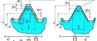
Metric thread. Profile.
Metric thread profile according to GOST 9150 (ST SEV 180)
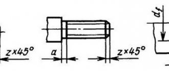
The nominal thread profile and the dimensions of its elements must correspond to those indicated in the figure and table.
d is the outer diameter of the external thread (bolt); D—outer diameter of the internal thread (nut); d2 is the average diameter of the bolt; D2 - average diameter of the nut; d1 - internal diameter of the bolt; D1 - internal diameter of the nut; P - thread pitch; H is the height of the original triangle; R is the nominal radius of curvature of the bolt root; H1 - working height of the profile.
Notes:
- The shape of the bolt thread root is not regulated and can be either rounded or flat-cut. A rounded cavity shape is preferred.
- The shape of the nut thread root is not regulated.
The table shows the dimensions of the thread profile elements. The shape of the screw thread cavities is not regulated by the standard; rounding of the depressions (with radius R) reduces stress concentration and increases the strength of the screw under cyclic loading.
According to GOST 24705 (ST SEV 182), the thread is metric, the main values of thread diameters are determined by the formulas:
where d3 is the internal diameter of the bolt.
Main settings
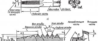
Each thread has precise geometric parameters.
Metric is characterized by a triangular thread profile, which is also called fastening. It is used for parts connected to each other by screwing. The profile size is determined by its height. The profile height (H) is the segment from the base to the top of an equilateral triangle, which is formed by a transverse section of the coil. The protrusions and depressions are made in the form of triangles with cut off vertices. In some cases, the depressions are rounded.
If the sides of each turn are mentally extended to the point of their intersection, then they will form a profile angle (α).
Thread profile
The main parameters indicated in the designation of a metric thread characterize its size. These include diameter and pitch. Metric thread designations indicate the main parameters.
Thread diameter is divided into 4 types:
- outer;
- interior;
- average;
- nominal.
Thread parameters such as stroke (Ph) and pitch (P) are interdependent and equal for a single-start system.
Thread stroke and pitch
The section separating the points of the same name on two turns is the thread pitch. There are main steps (large) and small steps.
Thread lead is a segment connecting two identical points on adjacent turns of the same thread. In the case where there are several entries, the move is expressed through the product of the number of steps and the number of entries.
The main thread elements also include:
- A surface inclined 45º in front of the inner or behind the outer is called a chamfer. It plays a role in connecting elements.
- Run-off is the place of transition to the uncut surface of the part. These two indicators are united by length, that is, a segment with turns, chamfer and runoff.
For metric threads, the main dimensions are summarized in tables of the relevant standards: GOST 9150-2002, GOST 8724-2002, GOST 24705-2004.
Possible structural deviations caused by the properties of materials are reported by tolerance fields, with values not exceeding the nominal profile formed by the maximum of the material. These indicators affect the accuracy of the thread fit - the density of penetration of the protrusions into the gaps.
Thread tolerance fields are divided into three accuracy classes. And also 4 types according to your preference.
Connecting thin-walled parts
If it is necessary to connect thin-walled parts, then it will not be possible to directly use a threaded connection: the number of turns may be too small to reliably hold the fastener within the thickness of the part. In such cases, a flange connection is used. In this case, the edge of the part adjacent to the joint is strengthened by special stamping or welding of a flange - a thickening in which holes are made and threads are cut. If the configuration of the product allows, then sometimes instead of a full flange, only nuts are welded at the fastening points.
Flange connection
If the parts to be connected are cylinders of the same diameter and thickness, there is another method: an internal thread is cut on one cylindrical surface, and an external thread of the same nominal diameter is cut on the other. Next, the parts are screwed onto each other. This connection method does not require the application of large forces to the fastening point and is used for lightly loaded structures, such as, for example, cylindrical instrument casings.
Measurements during the design and manufacture of threaded connections
The “bolt-nut” type connection is one of the most common in mechanics. When designing and manufacturing structures, the problem of how to measure a bolt with a caliper is often difficult.
Before starting work, it is worth remembering that the main dimensions of a bolt/nut are the length of the product and the diameter of the thread. A standard bolt of any design does not require such measurements. It’s a different matter when the bolt is made at home, or you need to measure the fastener without dismantling the connection. The following situations are possible here:
- Between the head and the opposite end of the rod there is a plane or part/plate, the dimensions of which do not allow the insertion of the measuring jaws of a caliper. In this case, using the main measuring scale and a depth gauge (sometimes called a “Columbic”), the height of the head, the thickness of the washer (if any), the thickness of the intermediate element and the height of the part protruding from the opposite side of the joint are determined. The obtained result is added up, and then, according to the tables of correspondence between the lengths of the rod and the “turnkey” dimensions that the bolt has, the standard size of the fastener is determined.
- The diameter of the thread on the bolt is unknown. Before taking measurements, it is worth remembering that for rod parts, the diameter of the external thread is determined by the diameter of its protrusions, and not the recesses. Therefore, by setting the required size on the external scale of the caliper, you can easily find out the desired value of the thread being measured. It should be equal to one of the standard values of the first (or, in extreme cases, the second) series of preferred numbers. Accuracy will increase significantly if the area being measured is thoroughly cleaned of dirt and grease. If the result for some reason does not fit into the standard, the depth of the thread is determined using a depth gauge. By subtracting twice the value of the parameter from the total value, you can check whether a used bolt with a cut part of the thread profile was used. This product should be replaced.
- The bolt being measured is completely “recessed” into the nut, and disconnection of the structure is undesirable. Using the external scale of the caliper, you should set the dimensions of the head - “turnkey” and the diameter of the circle of the protrusions. Then, using measurement tables, determine the standard size of the fastener. In the same way, measurements are made of other standardized fastening parts - studs, screws, etc. The exception is nuts. Here you will have to use internal sponges. In some instruments, it is necessary to add the thickness of the jaws themselves to the result obtained (it is indicated on the bar).
- How to measure thread pitch with a caliper? To do this, the bolt will have to be unscrewed. First, the height of the rod is determined using a depth gauge, and then the number of threads on it is counted. The difference will give the value of the tangent of the thread angle, i.e., the ratio of the unknown pitch to the outer diameter. The latter is already known, so finding out the thread pitch is no longer difficult. You can determine the thread pitch by directly measuring the distance between adjacent vertices, but this will be accurate enough only for fasteners that are completely free of contamination.
Rectangular thread
Table 3 presents data on rectangular threads.
Rectangular threads are most often made with a square tooth profile. But some manufacturers use rectangular profiles with an extended flange of the horizontal part for reinforcement
Table 3: Thread dimensions and helix pitch
| Nominal thread diameter d, mm | Step P | |||||
| 1 row (preferred) | Row 2 (permissible) | large | small 1 | small 2 | small 3 | small 4 |
| 8 | 2,00 | 1,50 | 1,25 | |||
| 9 | 2,00 | 1,50 | ||||
| 10 | 2,00 | 1,50 | 1,25 | |||
| 11 | 3,00 | 2,00 | 1,25 | 1,00 | ||
| 12 | 3,00 | 2,00 | 1,50 | |||
| 14 | 3,00 | 2,00 | ||||
| 16 | 4,00 | 2,00 | 1,50 | 1,00 | 0,75 | |
| 18 | 4,00 | 2,00 | ||||
| 20 | 4,00 | 3,00 | 2,00 | |||
| 22 | 8,00 | 5,00 | 4,00 | 3,00 | 2,00 | |
| 24 | 8,00 | 5,00 | 4,00 | 3,00 | 2,00 | |
| 26 | 8,00 | 5,00 | 4,00 | 3,00 | 2,00 | |
| 28 | 8,00 | 5,00 | 4,00 | 3,00 | 2,00 | |
| 30 | 10,00 | 6,00 | 3,00 | |||
| 32 | 10,00 | 6,00 | 3,00 | 2,00 | ||
| 34 | 10,00 | 6,00 | 3,00 | |||
| 36 | 10,00 | 6,00 | 3,00 | 2,00 | 1,50 | |
| 38 | 10 | 7 | 6,00 | 5,00 | 3,00 | |
| 40 | 10 | 7 | 6,00 | 5,00 | 3,00 | |
| 42 | 10 | 7 | 6,00 | 5,00 |
How to determine threads with a caliper or ruler
To determine the type of thread on the fitting, a caliper is needed.
How to correctly take measurements using a caliper is shown in the figure below.
Measurements must be made accurate to tenths of a millimeter.
| Outer diameter, mm | Inner diameter, mm | Thread pitch, threads per inch | Thread pitch | BSP | Metrics | Inch UNF | Inch NPT |
| 9,3-9,7 | 8,5-8,9 | 28 | 1/8″ | ||||
| 9,3-9,7 | 8,5-8,9 | 27 | 1/8″ | ||||
| 9,7-9,9 | 8,2-8,6 | 1,5 | M10x1.5 | ||||
| 10,9-11,1 | 9,7-10,0 | 20 | 7/16″-20 | ||||
| 11,6-11,9 | 10,2-10,6 | 1,5 | M12x1.5 | ||||
| 12,4-12,7 | 11,3-11,6 | 1/2″-20 | |||||
| 12,9-13,1 | 11,4-11,9 | 19 | 1/4″ | ||||
| 12,9-13,1 | 11,4-11,9 | 18 | 1/4″ | ||||
| 13,6-13,9 | 12,2-12,6 | 1,5 | M14x1.5 | ||||
| 14,0-14,3 | 12,7-13,0 | 18 | 9/16″-18 | ||||
| 15,6-15,9 | 14,2-14,6 | 1,5 | M16x1.5 | ||||
| 16,3-16,6 | 14,9-15,4 | 19 | 3/8″ | ||||
| 16,3-16,6 | 14,9-15,4 | 18 | 3/8″ | ||||
| 17,6-17,9 | 16,2-16,6 | 1,5 | M18x1.5 | ||||
| 18,7-19,0 | 17,3-17,6 | 16 | 3/4″-16 | ||||
| 19,6-19,9 | 18,2-18,6 | 1,5 | M20x1.5 | ||||
| 20,5-20,9 | 18,6-19,0 | 14 | 1/2″ | ||||
| 20,7-21,1 | 18,3-18,7 | 14 | 1/2″ | ||||
| 21,6-21,9 | 20,2-20,6 | 1,5 | M22x1.5 | ||||
| 22,0-22,2 | 20,2-20,5 | 14 | 7/8″-14 | ||||
| 22,6-22,9 | 20,6-21,0 | 14 | 5/8″ | ||||
| 23,6-23,9 | 22,2-22,6 | 1,5 | M24x1.5 | ||||
| 25,6-25,9 | 24,2-24,6 | 1,5 | M26x1.5 | ||||
| 26,1-26,4 | 24,1-24,5 | 14 | 3/4″ | ||||
| 26,3-26,7 | 23,7-24,1 | 14 | 3/4″ | ||||
| 26;6-26,9 | 24,3-24,7 | 12 | 1,1/16″-12 | ||||
| 29,6-29,9 | 27,4-27,8 | 2 | M30x2 | ||||
| 29,8-30,1 | 27,6-27,9 | 12 | 1,3/16″-12 | ||||
| 29,6-29,9 | 28,2-28,6 | 1,5 | M30x1.5 | ||||
| 32,6-32,9 | 30,5-30,9 | 2 | M33x2 | ||||
| 33,0-33,2 | 30,3-30,8 | 11 | 1″ | ||||
| 33,0-33,3 | 30,8-31,2 | 12 | 1,5/16″-12 | ||||
| 32,9-33,4 | 30,3-30,8 | 11,5 | 1″ | ||||
| 35,6-35,9 | 33,4-33,8 | 2 | M36x2 | ||||
| 37,6-37,9 | 36,2-36,6 | 1,5 | M38x1.5 | ||||
| 40,9-41,2 | 38,7-39,1 | 12 | 1,5/8″-12 | ||||
| 41,6-41,9 | 39,4-39,8 | 2 | M42x2 | ||||
| 41,5-41,9 | 39,0-39,5 | 11 | 1,1/4″ | ||||
| 41,4-42,0 | 39,2-39,6 | 11,5 | 1,1/4″ | ||||
| 44,6-44,9 | 42,4-42,8 | 2 | M45x2 | ||||
| 44,6-44,9 | 43,2-43,6 | 1,5 | M45x1.5 | ||||
| 47,3-47,6 | 45,1-45,5 | 12 | 1,7/8″-12 | ||||
| 47,4-47,8 | 44,8-45,3 | 11 | 1,1/2″ | ||||
| 47,3-47,9 | 45,1-45,5 | 11,5 | 1,1/2″ | ||||
| 51,6-51,9 | 49,4-49,6 | 2 | M52x2 | ||||
| 51,6-51,9 | 50,2-50,6 | 1,5 | M52x1.5 | ||||
| 59,4-59,8 | 56,5-56,8 | 11 | 2″ | ||||
| 59,9-60,2 | 56,4-56,7 | 11,5 | 2″ | ||||
| 63,3-63,6 | 61,3-61,8 | 12 | 2,1/2″-12 |
CONTACTS
st. B. Okruzhnaya 4-b, s. Petropavlovskaya Borshchagovka, Kiev-Svyatoshinsky district, Kiev region, 08130, Ukraine
Postal address: PO Box 70, Kyiv-162, 03162
information:
+38
branches
- Kyiv
- Sumy
- Krivoy Rog
- Kyiv
- Gorishni Plavni
- Vinnitsa
- Berdichev
- Kherson
- Khmelnitsky
- Pervomaisk
- Kyiv
- Lviv
SUPPLIERS
Manufacturers of components, materials and units
- ORLEN OIL
- Vitillo
- DLM
- Hydronit
- Fox-VPS
see everyone