21.07.2020
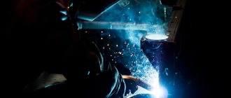
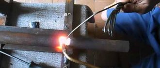
Let's consider one of the traditionally popular methods of restoring the original geometry of worn parts. The focus is on manual welding and arc surfacing: what technology is used to carry it out, what nuances arise, are there any pros, cons, features - we will try to answer every question.
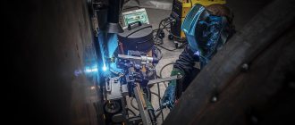
Let us immediately emphasize that these methods remain relevant and continue to be used in industry, even despite the general tendency towards automation. They are used in hard-to-reach places that cannot be reached with the help of equipment, as well as for spot and/or complex work. But the main thing is that they make it possible to apply layers of metal with the required physical and mechanical properties onto the surface with sufficient uniformity and thereby perform repairs on the required product.
Features of surfacing technology using manual arc welding
The basic conditions for its implementation are the same as in the standard case.
- • Before performing the procedure, the surface of the part must be thoroughly cleaned so that there is not the slightest trace of rust or a single greasy stain left on it.
- • The selection of electrodes is carried out depending on the conditions under which the element being restored is operated; the most common options are for alloy steels, or special flux-cored wires for wear-resistant coatings.
- • Power sources are transformers and serial rectifiers.
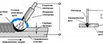
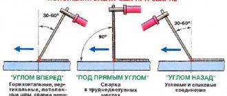
The work process is accompanied by the application of rollers. They should be used alternately - so that the previous one overlaps the next one by a third of the width; you can apply them using the so-called transverse vibration method - exactly the same as when enlarging a welding seam. It is also acceptable to create gaps and then fill them (after removing slag and cleaning). The main thing is that in the end the entire worn surface is evenly covered with a layer that restores its original geometry.
If we compare the technology with classical connection welding, manual metal surfacing has one important difference: in its case, the applied material can seriously differ from the base one in its chemical composition. Therefore, it is so important to choose the right electrodes so that they help provide a suitable structure (uniform and durable). When this cannot be achieved, it is worth giving preference to other solutions, for example, applying alloying powders, pastes, briquettes or immersion in a protective gas environment.
In this case, various techniques can be used, including automatic ones. But in all situations it is necessary to minimize residual stresses, deformations and tolerances.
Part preparation requirements
The quality of restoration largely depends on how correctly we prepare the part . This applies to welding, and especially surfacing.
The metal is thoroughly cleaned of rust using an angle grinder (angle grinder), better known as an “grinder.” Or with a hand brush. If necessary, chamfer or level.
In critical cases, during surfacing and soldering, the surface is degreased.
Sandblasting or waterjet treatment gives a good effect..
The cracks are cut with angle grinder grinding discs to the full depth to obtain V-shaped grooves in their place. Thick metal is processed on both sides. At their ends, to eliminate stress and prevent further development, through holes with a diameter of 4-6 mm are drilled.
Before fusing the holes, their edges are countersunk on one or both sides; if there is a thread, it is drilled out.
Considering that welding a car with an electrode or gas flame creates a high temperature, care should be taken to ensure the safety of adjacent finishing elements, electrical components. equipment, plastic parts.
To do this, remove the element being repaired or parts that may be damaged. If this is impossible for some reason, measures are taken to protect them (close them, cover them with wet rags).
What types of surfacing exist?
The variety we are considering is far from the only one of the current technologies. Therefore, we will pay attention to other options - also deserving the right to popularity - and then return to ours.
Submerged - carried out using wires - one or more, powder or solid, strip or round in cross-section.
In a protective gas - with immersion in a medium of hydrogen, nitrogen, argon; in this case, there is some overestimation of labor productivity - it is measured by the size, area or mass of the applied material.
Vibro-arc - the electrode is affected by vibrations with an amplitude of 0.75-1 of its diameter; this allows you to speed up the process and achieve a more uniform distribution of the restoration layer.
Electroslag - the coating is formed forcibly and strictly per pass, with convenient adjustment, due to which its total mass can reach hundreds of kilograms per hour (on dimensional parts); The performance of the method is impressive.
Plasma - with a compressed high-temperature jet as a heat source; The most common option today is a direct burner, although combined burners are also in demand. As an additive, you can take tape, wire, fine-grained powder, and the latter is especially convenient - it is easy to supply with gas and simply blow in, it quickly becomes liquid and spreads evenly over the surface.
Open arc - performed mechanically, without the use of a gaseous medium or flux. The method is quite universal and therefore makes it possible to restore even complex, concave or convex surfaces, small diameters and much more. Another area in which it is involved is the strengthening of products subject to consistently high loads.
Electrodes used
The selection of electrodes or welding wire is carried out based on three parameters:
- Type of metal.
- The required thickness of the part or surfacing layer.
- The level of responsibility of the part being restored.
When performing body repairs semi-automatically with carbon dioxide, flux-cored welding wire, copper-plated or plain, is used.
Surfacing of a layer with high hardness characteristics is carried out using electrodes of the T-620 type, with a thick coating including graphite, boron carbide, etc.
The required diameter of the electrode is selected based on the thickness of the metal being welded, according to special tables.
Aluminum parts are connected by gas (oxyacetylene) or arc welding. In the latter case, OZA-2 type electrodes are used. When using technology with a non-consumable tungsten electrode, a rod of the corresponding aluminum alloy is used as an additive.
When surfacing worn engine parts to obtain alloyed coatings, wire of the Np-65 type with a high carbon content is used. Work is carried out under submerged arc, in an environment of inert gases.
Manual arc surfacing: GOST and technical conditions
As a result of its implementation, the applied material may have the same properties as the base one, or others, thus changing the performance characteristics of the part. It all depends on the electrodes, and if in the first case they correspond to the interstate standard 9467-60, then in the second they correspond to 10051-62.
In standard situations, preference is given to “E” and “F” type rods. Particularly interesting are the options with calcium fluoride coating from the U and UONI series. Because they produce a fine-grained material characterized by high impact strength, and this is the key to the absence of cracks.
Please note that the technology of manual arc surfacing of steel depends on the chemical composition of the part. If the proportion of carbon in it is no more than 0.25%, work can be done at any temperature. But the higher the percentage of carbon, the more likely it is that hardening structures will appear at points of thermal impact. Therefore, products containing 0.25-0.5% C must be heated to 120-350 0C.
How many layers should I do? It depends on the overall thickness that needs to be maintained. It is important to ensure that their distribution is correct - so that the new one goes along the upper third of the previous one. Why? Because it is in this section that there are the fewest pores and foreign inclusions, which means it is best suited for creating a strong seam.
At what current is manual welding and surfacing of parts carried out? This is influenced by a number of factors, in particular, the brand and diameter of the selected electrode, the quantity, weight and height of the final coating. The smaller the product, the lower the amperage should be, and vice versa.
Deformations that arise during labor can be reduced; to do this, it is enough to make one or more (depending on the situation) of the following rational decisions:
- • heat the part to 200-400 0C;
- • bend the product in the opposite direction;
- • immerse the object in water, but do not wet the work surface;
- • arrange the rollers symmetrically (thereby balancing the force effects);
- • rigidly fix the workpiece in a jig or similar device - so that it can be removed only after cooling is complete;
- • correctly distribute the additive over problem areas, for example, in a spiral, with application on the reverse side, with a breakdown of large planes;
- • relieve internal stresses using high-temperature tempering - with heat treatment at 650 0C.
How does the process work?
Manual arc surfacing is performed using consumable or non-consumable (graphite, carbon, tungsten, hafnium) electrodes. The formation of a seam in the first case occurs due to the interaction of the applied material and the base metal (surface of the part), in the second - due to the additive. Option 1 is more popular, since it can be implemented in any spatial position, and it is suitable for workpieces and elements of any shape.
Attention, the coating of the rods can be very different, but in practice three are the most common. The specifics of performing the work for each of them are somewhat different, so we will consider everything.
Acidic substances are aluminosilicates, oxides and deoxidizing agents. When its components begin to melt, a protective gas is released. The nuances are as follows:
- • Welding can be carried out under both direct and alternating current. In both cases, the surface of the part is actively exposed to carbon, which causes the bath to boil (but this has a very positive effect on the quality of the joint). The seam turns out smooth and tight, even if the work was carried out on rust or scale.
- • The material is often heavily splashed, in the process harmful manganese compounds are released into the atmosphere, and there is a tendency for crystallization cracks to quickly appear. These shortcomings somewhat limit the use of electrodes OMM-5, OMA-2, TsM-7 and others from the same group.
The main ones are fluorspar, deoxidizers, marble, alloying additives like ferromanganese. When heated, carbonates dissociate and thus provide gas protection.
The use of manual arc surfacing using rods from the UONI, OZS, VN, VSOR series is quite convenient, since it allows you to obtain a restoring layer with a small amount of harmful impurities, but with high impact strength and ductility (even at sub-zero temperatures), resistant to aging and formation of cracks. This is an option for connecting rigid structures made of low-alloy, carbon, cast steels.
The downside is that pore formation increases significantly if:
- • increase the length of the arc;
- • moisten the contact surface;
- • oil, rust, and scale will appear on the edge of the product.
Work should usually be carried out with direct current, and its polarity should be reversed. The variable can only be connected when lightly ionizing elements are introduced into the coating (that is, soda ash, potassium liquid glass, potash and other additives).
Rutile is aluminosilicates, concentrate, ferromanganese, with gas protection due to cellulose. The rods used (from the OZS, ANO, MR series) help to form an even seam - with little spattering and formation of pores, with good slag separation - but require preliminary calcination for 2-2.5 hours at a temperature of 80-120, 200 -250 or even 300-350 0C.
Attention, the technique and technology of manual arc surfacing with coated electrodes involves the participation of the base metal in the creation of the restoring layer. Its share usually varies in the range of 0.3-0.45 m - this is enough to maintain a stable arc. This value can be reduced (thus minimizing the loss of the original geometry of the part) due to transverse vibrations - use them and bring m to 0.25. But remember that further reduction is undesirable, since along with it the likelihood of lack of penetration will proportionally increase.
When using graphite or carbon rods, it is recommended to work at direct current with straight polarity and make one restoration layer: to make it 2-3 mm thick, 6-8 mm of additive should be applied.
When restoring parts, acetylene is most often used as a flammable gas. The temperature of the acetylene-oxygen flame at its hottest point is 3000-3150 ° C. With gas welding, the rate of heating and melting of the metal is much lower than with arc welding, and the heat-affected zone is much larger, so it is not recommended to use gas welding to repair damage to parts, made of cast iron.
Carbon dioxide arc welding is one of the most effective processes for repairing damage in thin steel parts. It is increasingly replacing gas and manual electric arc welding in the repair of cabins, bodies and critical metal structures. This type of welding is characterized by high productivity, good formation of the weld, ease of the process in all spatial positions, and heat concentration in the welding zone.
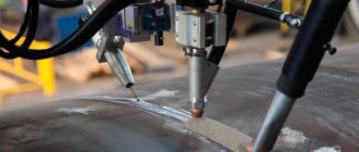
Automatic surfacing under a layer of flux (Fig. 86) ensures the highest quality of the deposited metal, since the welding arc and the liquid metal pool are completely protected from the harmful effects of atmospheric oxygen, and slow cooling contributes to the most complete removal of gases and slag inclusions from the deposited metal. During automatic surfacing, the specified mode remains almost unchanged.
When surfacing under a layer of flux, an electric welding arc burns in a closed cavity of molten mineral substance (flux). The flux prevents splashing of liquid metal, ensures the formation of a normal weld, and protects the molten metal from the action of oxygen and nitrogen in the air, which negatively affect the properties of the deposited metal. The electrode wire from the cassette is fed to the welding site by an automatic head.
Rice. 86. Scheme of mechanized surfacing under a layer of flux: 1 - current source for powering the arc, 2 - shell of liquid flux, 3 - device for supplying flux, 4 - mouthpiece, 5 - electrode wire, 6 - electric arc, 7 - slag crust, 8 - deposited layer, 9 - deposited part, 10 - sliding contact
The use of flux made it possible to use bare (uncoated) electrode wire. The current is supplied to the wire via sliding contact 10 at a short distance from the arc, which has reduced the length of the electrode through which the welding current flows. At the same time, the current density increased several times, and the surfacing productivity also increased. The arc is most often powered by current from welding generators or rectifiers.
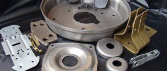
By surfacing under a layer of flux, it is possible to restore worn flat, cylindrical, threaded and other surfaces of parts. The cylindrical surfaces of parts deposited under a layer of flux must have an outer diameter of more than 50 mm, since on smaller sections the molten flux and slag do not have time to harden due to high heating and flow off the parts. By mechanized surfacing under a layer of flux, rollers, wheels, shoes, shafts, rollers, drums, etc. are restored.
Varieties of electric arc surfacing under a flux layer are more productive surfacing with a strip electrode, as well as welding and surfacing with flux-cored wire.
Automatic surfacing with a strip electrode is carried out with a special electrode made from cold-rolled metal strip with a thickness of 0.4–1.0 and a width of 20–100 mm. Due to the fact that with this surfacing method the welding arc continuously moves along the end of the strip width, the penetration of the base metal is shallow and its share in the deposited layer is 8-10%. Thus, the influence of surfacing on the structure and mechanical properties of the base metal is insignificant. The chemical composition of the tape and the brand of flux are selected depending on the purpose of the surfacing.
The method provides high productivity: in one pass it is possible to deposit a layer with a thickness of 2-7 mm and a width corresponding to the width of the tape.
Disadvantages of the method: the need for tape of various widths for surfacing different types of parts; impossibility of using surfacing for shafts of small diameters, spline joints, internal holes. Semi-automatic welding and surfacing with flux-cored wire is a relatively new process in the repair industry. The essence of the method is that a special wire is used as the electrode material, into which, along with alloying elements, protective gas and slag-forming substances are introduced, thereby achieving high hardness and wear resistance of the deposited metal. For surfacing with flux-cored wire, the same automatic and semi-automatic machines are used as for welding and surfacing with solid electrode wires under a layer of flux. Flux-cored surfacing is recommended to be used primarily for the restoration of parts with high wear.
When eliminating defects in cast iron body parts (cracks, breaks, holes), self-shielding wire PANCH-11 is used without heating and additional protection. Compared to special nickel electrodes, PANCH-11 wire has high resistance of welded joints against heat-affected cracks. Cracks are welded with self-shielding wire PANCH-11 with an open arc at direct current of direct polarity in sections 20-50 mm long with forging and cooling of each section to a temperature of 50 ° C. For welding, semi-automatic machines PDPG-500, PDG-300, A-547U, A- are recommended 825M complete with rectifiers VS-300.
When semi-automatic welding of cast iron with self-shielding wire PANCH-11, the process proceeds stably, without spattering of metal, the welding seam is formed without undercuts, sagging and other external defects. The weld metal has high machinability, density and strength. This method is increasingly used in repair plants; it can be recommended for cold welding of cracks up to 200 mm long, breaks, and welding of patches on thin-walled cast iron parts.
Vibrating arc surfacing is a type of automatic electric arc surfacing. It is carried out by an oscillating electrode, which makes it possible to deposit metal at a low voltage of the current source. Thanks to this, the smallest possible weld pool is formed, a small-droplet transition of metal from the electrode to the part. With vibration-arc surfacing, fairly good fusion of the base metal with the electrode metal, slight heating of the part and a small heat-affected zone are obtained. Vibrating arc surfacing in a coolant environment is the most widely used.
A schematic diagram of an installation for vibro-arc surfacing in a liquid environment is shown in Fig. 87. A wire is fed to the worn part installed in the machine using rollers along a guide nozzle, which is unwinded from the drum. Simultaneously with the supply of wire from the vibrator, an oscillatory motion with a frequency of 50-100 Hz is imparted to the electrode. Installing a vibrator allows you to reduce the arc power without reducing the stability of the process. From a direct current source, a plus is supplied to the electrode through the rollers and the mouthpiece, and a minus is supplied to the part through the machine spindle.
Rice. 87. Installation diagram for vibrating arc surfacing in a liquid stream: 1—inductance, 2—generator, 3—pipeline, 4—feed rollers, 5—drum for electrode wire, 6—vibrator, 7—springs, 8—gear pump, 9— settling tank, 10 - part with a deposited layer, 11 - surfacing zone, 12 - mouthpiece
Liquid is supplied to the surfacing zone through the pipeline in a continuous stream. The liquid flows from the part into the pan of the machine, from where it enters the settling tank and is then pumped through pipelines and again supplied to the part.
The vibro-arc method can be used to fuse cylindrical surfaces with a diameter of 15 mm and above, the surfaces of worn holes, movable and fixed joints; surfaces for cages of ball and roller bearings; journals of shafts operating in plain bearings that do not experience shock loads; necks in places of press fits. Vibration-arc surfacing is undesirable for profile surfaces in the form of threads, small splines, etc. Vibration-arc surfacing can also be performed under a layer of flux and in a protective gas environment.
The method of vibrating arc surfacing and welding of various materials in an air stream is used in the restoration of cast iron parts. The part is welded using an automatic vibrating arc head, and atmospheric air is supplied to the welding zone to obtain dense and easily processed layers. With increasing air supply, the external porosity of the deposited metal decreases. The lowest porosity is obtained at an air flow rate of over 1600-2000 l/h.
Rice. 89. Semi-automatic A-547U complete with rectifier BC-300: 1 - carbon dioxide cylinder, 2 - heater, 3 - flow meter, 4 - holder with hose, 5 - feeding mechanism, 6 - welding rectifier, 7 - remote control management
The deposited metal has low hardness, which allows turning the layer with a conventional tool. For surfacing, an installation is used, consisting of a lathe, a current source (three VSG-ZA rectifiers) and an automatic vibrating-arc head.
When surfacing in a carbon dioxide environment, the welding arc and molten metal are protected from the harmful effects of air by a stream of carbon dioxide, specially supplied to the welding zone. The electrode wire from the cassette is continuously fed into the welding zone at a given speed. Current is supplied to the wire using a mouthpiece and tip located inside the gas torch, which supplies shielding gas to the welding zone.
Rice. 88. Scheme of the surfacing process in a carbon dioxide environment: 1 - torch, 2 - electrode wire, 3 - mouthpiece, 4 - tip, 5 - torch nozzle, 6 - base metal, 7 - welding arc, 8 - weld pool, 9 - seam
The electrode wire melts under the heat of the arc; the electrode metal goes into the weld pool and mixes with the molten base metal. As a result of the fusion of the electrode and base metals, a weld bead is formed, firmly connected to the base metal.
During surfacing, carbon dioxide from the cylinder (Fig. 89) passes through a gas heater, dryer, reducer and flow meter (rotameter). When leaving the cylinder, carbon dioxide expands and its temperature drops sharply. To prevent sudden cooling of the gas and freezing of the moisture contained in carbon dioxide, it is passed through a heater immediately after leaving the cylinder. The carbon dioxide then enters a desiccant, which is a cylinder filled with a substance that absorbs moisture from the carbon dioxide (silica gel, anhydrous copper sulfate or calcium chloride).
Surfacing in a carbon dioxide environment has a number of advantages over other surfacing methods: higher labor productivity compared to submerged surfacing, high efficiency of the process, good quality of the deposited metal; the possibility of surfacing the internal surfaces of products of complex shapes and small diameters; improving working conditions for workers. In addition, there is no need to use various devices to retain flux and molten slag, as in submerged surfacing, which allows for increased automation of the process. Disadvantages of the surfacing method in a carbon dioxide environment: large losses of metal due to spattering, the need to use special types of wire and special power sources.
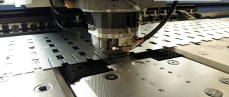
The essence of the process of electric contact welding of steel strips is welding steel strips to the surface of parts with powerful pulses of electric current. At the welding point, under the influence of a current pulse, the metals of the filler material and parts are melted. The filler material (steel strip) does not melt over the entire thickness, but only in a thin surface layer, in the area of contact with the part. The layer is welded to the entire worn surface by controlled current pulses during rotational movement of the part at a speed proportional to the pulse frequency and translational movement of the welding head. A diagram of the tape welding process is shown in Fig. 90.
For welding the tape, the 011-1-02 installation is used, which allows you to restore the external and internal cylindrical surfaces of parts. The technological process is advisable to use when restoring shaft journals for rolling bearings, mounting holes of bearing cups and other parts with wear of up to 0.4 mm.
The worn surface is pre-ground, removing a layer of metal 0.15-0.2 mm thick. After this, the part is submitted for installation. Place a measuring piece of steel tape with a thickness of 0.4-0.8 mm (depending on the amount of wear) on the prepared surface, which is pressed with the welding rollers of the installation. Belt material - medium and high carbon steel grades 45, 50, 65G, etc.
Current pulses grab the tape in several places. Moving the rollers to the extreme position, switch the installation to operating mode and weld the tape.
Rice. 90. Scheme of the process of electric contact welding of a steel strip: 1 - centers, 2 - part to be restored, 3 - rollers, 4 - strip, 5 - transformer, 6 - current breaker
The process is carried out by supplying liquid (water), which cools the rollers of the welding head and at the same time effectively removes heat from the welding zone. In this case, the hardness of the restored surface increases to HRC.55 or more. This achieves a combination of coating and heat treatment technologies. Subsequent mechanical processing after welding of the tape is carried out on cylindrical grinding machines.
The use of electric contact welding of steel strip instead of vibro-arc surfacing makes it possible to increase the productivity of parts restoration by 2.5 times, reduce the consumption of filler materials by 4-5 times, the labor intensity of work by 2.5 times and increase the life of the part to the level of a new one.
Electrical contact welding of steel wire is used mainly for thread restoration. The wire is fed into the cavity of the worn thread and pressed with a contact roller. After turning on the current, it is welded. The diameter of the wire is selected in such a way that after welding and upsetting, the metal fills the cavity between the turns of the restored thread and at the same time there remains an allowance for machining. The best results are obtained if the diameter of the filler wire is equal to the thread pitch or greater than it by 5-10%.
Equipment for manual arc surfacing
The power source can be a step-down transformer: at a low output voltage it will give a large amperage, which is convenient. Rectifiers are also often chosen: by converting them, instead of the standard “mains” 220 V and 50 A, it is quite possible to get 600 A at 17-45 V. Inverter machines are also quite popular - due to their relatively small weight and size. Electric generators are becoming portable connection points, but they are quite expensive to operate, which limits their relevance.
The specialist performing the work must protect himself from accidental injuries - wear gloves and a mask with a “chameleon” light filter, which protects the eyes from the harmful effects of UV radiation.
Materials for manual arc surfacing deserve special attention. These are either electrodes, or wires and tapes, or hard alloys. We have already considered the first two options, let's take a look at the third.
Most often these are boride- and carbide-forming metals such as manganese, chromium, titanium, tungsten, combined with iron, nickel, boron, cobalt, both in powder and cast form. A typical representative of the first category is stalinite, the second is rod sormite.
Cases in which they are relevant:
- • restoration of machine tools and production mechanisms;
- • creation of stamps;
- • repair of parts used under severe wear conditions.
Manual arc surfacing modes
You need to choose one of them based on a number of parameters - additional and basic, which ultimately determine the size and quality of the seam.
The main characteristics are:
- • current strength - in general, it should be higher, the thicker the diameter of the electrode and the base metal;
- • arc voltage (length), defined as the distance from the end of the rod to the surface of the workpiece - it is important to keep it short and stable;
- • speed – the faster the work is done, the less spreading of the material, but the higher the risk of lack of penetration, so it is necessary that the process occurs evenly;
- • type and polarity of the current – reverse is relevant for thin-sheet and high-alloy items (so as not to burn or overheat them), direct – for massive parts.
Additional parameters include the number of passes, the thickness and chemical composition of the applied layer, and the location of the joint.
Types of manual welding and surfacing
There are several parameters by which they are classified.
For example, there is a common division:
- • by the nature of the arc – compressed (short) and free (long);
- • according to the type of electrode used – with a melting rod (coated) and not;
- • according to the effect on the base metal of the part - direct, three-phase, indirect.
They are also grouped according to the result, that is, according to the restored layer - into:
- M – thin;
- C – average;
- D – thick;
- G – especially thick.
They are classified separately by purpose - options for connection are distinguished:
- • low-alloy and carbon steels;
- • alloyed and heat-resistant;
- • alloys with special properties;
- • layers with non-standard characteristics.
Now we will schematically consider the main methods of manual arc welding and surfacing:
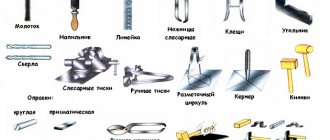
They use:
A – carbon electrode (1) and bulk alloy (2);
B – coated (1) and alloying layer (2);
B – tungsten conductor (1) and filler rod (2) in inert gas;
G – rod (1) in a protective environment;
D – wire (1) and flux (2);
E – tape (1);
G – plasmatron jet (1) and powder (2), already sintered or applied;
Z – conductor (1), copper slider (2), workpiece (3), restoring coating (4).
The choice of a specific option depends on the specific conditions in which the work is carried out, on the planned result and on the required productivity. But each of them can be implemented quite simply and quickly.
Equipment used
With all the variety of work methods and tooling, the classification of welding during car repairs comes down to only two types:
- Electric, mainly arc using shielding gases or fluxes.
- Gas, using acetylene or propane.
Electric is divided into manual, semi-automatic in an inert gas environment, submerged, etc.
There are other methods, such as laser, friction, and diffusion welding. However, they are practically not used for car repairs.
In some cases, a type of welding is used, such as soldering . It is used to repair damage to pipes made of non-ferrous metals, radiator blocks, and parts of refrigerator equipment made of thin copper.
Which welding is best for welding a car body depends on the nature of the damage, as well as the characteristics of the place or part that needs to be restored.
Today, the majority of work is carried out using electricity. Gas welding, which was once almost the only method of repair, is today used to connect parts made of thin metal.
In addition, oxy-acetylene welding is still popular where various rods that create dynamic loads are attached to the body .
Electrical appliances for small repairs include car welding using an inverter or a conventional manual welding machine. For delicate work that requires high quality, as well as surfacing, semi-automatic machines with carbon dioxide or inert gas are used.
With the spread of aluminum and titanium alloys, the arsenal of repair mechanics was replenished with arc welding devices using a non-consumable electrode in an inert gas environment. With feeding of the melting filler rod by hand or automatically.
Manual arc surfacing of metal: diagram
It looks like this:
And in it:
1 – part with base metal;
2 – bath in which operations are carried out;
3 – electric arc of a certain length (preferably stable);
4 – fused layer;
5 – restorative coating;
6 and 7 – solidified and liquid slag, respectively;
8 and 9 – rod, already melted (8) and not yet (9);
10 – holder.
Gas welding
Electric arc welding is more economical and creates a more reliable welded joint compared to gas welding. Proper preparation of the part for welding ensures high quality of the deposited layer and its strong adhesion to the base metal. Before welding, the parts are cleaned and their edges are cut. The surface of the parts is cleaned with a steel brush, file, emery cloth, abrasive wheel, sandblaster, then washed with gasoline or kerosene, and also subjected to alkaline etching. The edges of sheets being butt welded are cut (beveled) at an angle (60-70°), and the edges of breaks and holes are leveled.
N
Melting is one of the main methods for restoring parts. It is widely used in cases where rubbing surfaces need to be given greater wear resistance. Two, three or more layers are often deposited with hard alloys, which makes it possible to increase the service life of parts several times. The quality of surfacing largely depends on the condition of the surface being restored. Cast iron and mild steel parts are degreased before surfacing to remove oil from pores and cracks. To do this, the surface of the part is burned with a gas torch, blowtorch or in heating furnaces. Soot and oxide deposits after firing are removed from the surface of the part with an emery cloth or rag moistened with kerosene or gasoline. The area of the part for surfacing is treated with steel brushes or abrasive wheels.
3 pages, 1161 words
Gas-flame surfacing
... clean the surface with emery and perform surfacing. Sometimes gas-flux surfacing is used, in which the flame temperature is less than 700°C. In such cases, surface cleaning is not required. The surfacing process is carried out using the left method from bottom to top, the workpiece...
Restoration of parts by metallization
Metallization is the application of molten metal to the surface of a part. Molten metal in a special device, a metallizer, is sprayed into tiny particles by a stream of air or gas and transferred to the previously prepared surface of the part. The applied layer is not monolithic, but is a porous mass consisting of tiny oxidized particles. Using the metallization method, the dimensions of the seats for rolling bearings, gears, couplings, crankshaft journals, etc. are restored. In order for the metallization layer to be firmly connected to the surface of the part, the surface is cleaned of dirt and oil and sandblasted. The hardness of the metallization coating is determined by the quality of the applied material.
Examples of similar educational works
Operation and repair of hydropower equipment of hydroelectric power plants
... uninterrupted supply of electricity of a certain quality. During his duty, the hydraulic unit operator is the person... The service area of the hydraulic unit operator includes: unit control panels, hydraulic units with their auxiliary...
Study of technological processes and equipment of an oil and gas repair enterprise...
... such types of work as: Overhaul and ongoing repairs of drilling and oilfield equipment Overhaul and ongoing repairs of blowout prevention equipment Conservation of equipment, guarantees for work performed Manufacturing of spare parts, non-standard ...
Maintenance and repair of gas equipment
... more and more car owners are installing equipment on their cars to run the engine on liquefied gas. Below... Along with the above advantages, gas equipment also has disadvantages: Reduced luggage compartment capacity...
Organization and planning of repairs of technological equipment of chemical production
... the workshop is headed by a mechanic, foremen and foremen directly supervise the work of supervision, care, operation and repair (with a decentralized system) of equipment. The foreman reports to the shop mechanic, and the foremen report to the duty officers...
Organization and planning of repairs of technological equipment of chemical production...
… 4 — Annual labor intensity of repair of technological equipment Name of equipment Technical characteristics Number of units. equipment Operating time between repairs (downtime during repairs), h Structure of the repair cycle Number of repairs per year for all ...