21.07.2020
You can create strong joints and restore worn coatings in different ways. Today, one of them is under the spotlight, namely mechanized welding and surfacing: let’s look at what it is and what methods can be used, let’s analyze the advantages and disadvantages it has.
Please note that it has a wide scope of application: it is performed both in the manufacture of a wide variety of building structures (most often pipes), and in the repair of actively used functional units. With the help of one or another of its types, the original geometry of crankshaft journals, gearbox splines and gearboxes, track undercarriage elements and many other items is returned. Currently, it is considered the most promising direction, which means it is actively developing.
What is called mechanized surfacing?
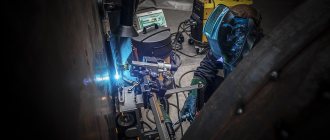
In general, this is the process of applying a special layer to a worn surface, which, once hardened, will not only restore the original shape of the part, but will also become a kind of protective coating. The whole point (and the main feature) here is how this type of work is carried out, and it can be implemented in one of two options:
- • automatically – both the supply of electrode material and its movement (and workpieces too) in space are performed by equipment; many installations also provide transverse vibrations of the guided rod, which reduces the number of passes;
- • semi-automatically – mechanically, only the wire (or other additive) is delivered to the work area through a hose, after which the welder independently moves the holder with it relative to the workpiece.
Each has its own characteristics. So, in the first case, there may not be enough flexibility in positioning; in the second, much depends on the skill of the person solving the problem. Although labor productivity in both situations is much higher than with any of the manual methods (they have other advantages). The quality and uniformity of the coating are usually also better, which determines the breadth of application, especially in serial applications.
Mechanical surfacing technology
- • The initial stage is cleaning the surface of the part from residual lubricants and dirt. You can either gently burn it with a torch, or wash it with a hot alkaline solution and then go over it with a brush. This is necessary for the most uniform deposition of the restoring layer.
- • The next step is to prevent significant internal stresses (if there is a possibility of their occurrence) in order to prevent the appearance of cracks in the applied coating. To do this, it is necessary to heat the element being processed to a certain temperature. Until which one exactly? Depends on the size, shape, characteristics of the workpiece, as well as the final properties of the additive.
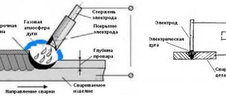
- • Well, then the melt is carried out - wire, metal strip, powder - and the direct application of additional material to the base material, with or without submerged arc, under gas protection or without it. If separate rollers are applied, you should ensure that each subsequent one overlaps 0.4-0.5 of the width of the previous one.
It seems that everything is simple, and with the right level of experience it is, but it is important not to forget that the correct mechanized surfacing technique requires taking into account a number of nuances. Even during preparation you need:
- • sand the working surfaces of the object with sandpaper if it has previously undergone a restoration procedure;
- • plug the holes coming into the contact zone with graphite rods or immediately with a paste based on liquid glass, and do this in advance, about a day in advance;
- • remove remaining lubricant using specially pierced rubber washers installed in front of the heads;
- • secure the part in the chamber with sufficient reliability - so that the runout does not exceed 1.5 mm.
You just need to adhere not only to the chosen method (we will discuss the methods in detail below), but also to the melting mode. The latter depends on a number of factors, including the magnitude of voltage and current, the nature of rotation of the workpiece, the feed speed, and even the angle of the wire or its length.
The issue of forming rollers also has its own specifics: when applying them, it is important to boil the base material shallowly, so that its share in the coating does not exceed 0.3-0.45 m. At the same time, you cannot arc too quickly, otherwise the layers will turn out narrow and the quality of adhesion will suffer.
There are also restrictions on the extension of the filler rod: the larger it is, the greater the resistance of the chain, the more difficult it is to perform the work. It has been found in practice that this value should not exceed 25 mm.
Welding high-alloy and tool steel
The main difficulties in welding
- Cracks form in welds due to the strong hardening of the metal in air.
- The result is seams with great chemical heterogeneity.
Welding Features
- Before welding, workpieces must be in an annealed state and thoroughly cleaned.
- Before welding, workpieces must be heated to a temperature of 250...300 °C.
- When welding, flux must be used.
- The flame should have a slight excess of acetylene.
- After welding, the hot products must be placed in an annealing oven.
In addition to various steels, the flame of a gas torch can weld cast iron, copper, brass, and bronze. Gas flames are widely used in repair welding of cast iron, for surfacing, and also for soldering various metals. The gas flame can provide the process of separating metals or oxy-fuel cutting.
Types of mechanized surfacing
Today the following methods are relevant:
- • submerged;
- • in a protective gas environment;
- • electrical contact;
- • electroslag;
- • vibro-arc;
- • plasma.
Now let's look at each of them in more detail.
Submerged arc work is convenient because when it is carried out, the air does not affect the hot metal, which helps to avoid pores and generally makes work easier. Plus, there is no spattering, the generated heat is used more efficiently, and alloying can be done.
The process itself is distinguished by its productivity, and there are two reasons for this:
- • The overhang is relatively small, so the current (not per unit area of the rod) is 7-8 times higher than with manual arc welding.
- • The resulting slag helps to minimize losses of the base material, which has a positive effect on the final soldering coefficient (increases it by 1.5-2 times).
The role of the electrode is performed by a solid wire with a cross-section of 1-6 mm; its feed speed is regulated by an automatic device and ranges from 100 to 300 km/h. The “plus” is supplied to it from the source (through a copper mouthpiece), while the “minus” is supplied to the workpiece itself (but the current still passes through the frame and the puller).
In this case, the flux can be glassy, representing a crushed mixture of silicates (AN series), and only protect the base material from air. Or contain alloying, binding, slag-forming, deoxidizing additives and change the physical and chemical properties of the applied coating.
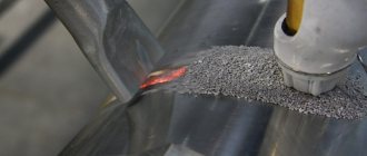
Mechanized surfacing of the surfaces of parts in a protective gas environment is carried out in a space filled with a mixture of argon and water vapor or CO2. The first is expensive, so factories use CO2 by default when repairing bodies, cabin elements and tails, and many other parts in it.
The process proceeds as follows: carbon dioxide supplied to the working area displaces air, preventing oxygen or nitrogen from negatively affecting the created seam. The only problem is that the arc heats up to 6000 0C, and at this temperature the bonds in CO2 are broken, and the reaction of its disintegration provokes the burnout of alloying substances and carbon in the applied coating. To mitigate possible harm, you should use a special filler wire from the Sv series, which contains additives of titanium, silicon, and manganese.
This option has four advantages:
- • allows you to obtain an even, dense and even aesthetic layer (without slag), which does not require any subsequent processing;
- • makes it possible to resolve the issue 1.5-3 times faster than manually;
- • provides all conditions for visual control of the process;
- • promotes parallel cooling of the workpiece, which is why the surface of the workpiece does not warp.
Among the disadvantages we will write down the relative fragility of the seam and the relatively large spattering.
But the method is easy to implement in practice: a standard 40-liter carbon dioxide cylinder is enough for 20 hours of work. It is not a problem to neutralize the moisture contained in it with a desiccant - copper sulfate. An ordinary oxygen reducer would be an excellent reducer. All operations must be carried out with a current of reverse polarity.
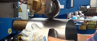
There are both classical and modern mechanized methods of welding and surfacing of parts. Electrical contact rather belongs to the second category, since it is performed on modernized equipment. To implement it, machines are used that weld wire or strip metal in one or several passes, and thus create a uniform coating of the required thickness (up to 3 mm). It is more rational if there are 2-4 layers: this will preserve all physical and mechanical properties, excluding overheating during work.
Mixing of the main and additional material tends to zero, especially when using intermediate additives - PG-SR powders. At the same time, it is quite possible to maintain productivity at the level of 2-4 kg/h.
The electroslag method allows you to repair even heavily worn elements, for example. It ensures high quality welds, and the work can be done really quickly; a figure of 30 g/Ah is quite realistic.
The scheme is as follows:
- • the flux is heated by an arc, after which a current is passed through it;
- • under such conditions, the electrode melts and forms a pool together with the base metal;
- • The crystallizer moves upward at a certain speed, and the lower layers gradually cool down.
Please note that the working area in this case is completely protected from the influence of air, so nothing prevents you from introducing alloying additives and using the generated heat with maximum efficiency.
The technique and technology of mechanized surfacing using the vibration-arc method comes down to the use of a filler rod that creates vibrations with an amplitude of 1 to 3 mm and a frequency of 50 to 100 Hz. As a result, the entire process becomes a series of three cyclically repeating stages:
- • combustion;
- • idling;
- • short circuit.
Moreover, in the first step, up to 9/10 of the total heat is released, and in the third – only 1/10. This is explained by the fact that 12-20 V, i.e., at a low voltage of the current source, there is inductance in the circuit, which means the arc remains stable, and its voltage is already 30-35 V.
For maximum efficiency, it is worth connecting the current with reverse polarity and performing work in a cooling liquid environment. An aqueous solution of glycerin (10%) or soda ash (5%) applied 40 mm from the filler rod works well. As a result of heating, it will turn into steam, which will take away harmful nitrogen compounds. In addition, Ca will make combustion more stable, and C3H8O3 will prevent cracks from appearing.
Yes, the method is good due to its small temperature rise zone and almost complete absence of losses of alloying elements and allows you to obtain a thin but durable coating, but it also has a drawback. The downside is that the fatigue strength of the workpiece is reduced due to the appearance of pores in the applied layer, which partially limits applications.
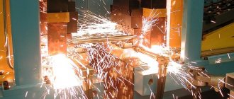
If we consider modern mechanized surfacing methods, then plasma technology is considered the most progressive. In accordance with it, the restoration of a worn surface is carried out under the influence of highly heated and richly ionized gas - argon, helium, air, nitrogen with additives.
It can be carried out according to one of three schemes - with an open, closed and combined jet. In the first case, the role of the anode is played by the workpiece, in the second by a burner or nozzle, in the third by both.
There are also two implementation options:
- • plasma captures the powder and deposits it evenly onto the surface;
- the additive is immediately introduced into the stream.
The method has five practical advantages:
- • due to the concentration of high temperature, the thermally affected zone narrows;
- • thanks to it, it is possible to apply a variety of wear-resistant materials, even plastic, to steel;
- • allows you to precisely adjust the layer thickness - from thin, 0.1 mm, to 2-3 mm;
- • has a relatively high arc efficiency – reaches 45%;
- • it can also be used for surface hardening.
Alloy steel welding
Main difficulties
- The metal is hardened, and the more carbon and alloying additives there are in the steel, the more cracks and cracks form in the weld.
- Burnout of alloying elements from the molten metal occurs.
Welding Features
- It is necessary to gradually heat the metal at the start of the seam.
- Sutures should be applied as quickly as possible, avoiding overheating of the metal.
- At the end of the seam, slowly, gradually remove the flame, forming reinforcement at the end of the seam, as well as heating the increased area of the metal.
- Avoid welding metal at low temperatures. Ensure slow cooling of the welded joint.
- Before welding, the workpieces must be in an annealed state.
Equipment for mechanized surfacing
Usually these are installations, the “heart” of each of which is a converted lathe: instead of a tool holder, it has a head, it is also equipped with a power source and often a reduction gear that reduces the rotation to 5 or even 2 rpm.
Although there is a technique for crankshafts that does not require additional modification. These are machines like OKS-5523 with universal centrifuges, and they regulate the speed steplessly.
Current sources can be connected to a variety of sources, for example, it could be:
- • rectifier from the VKS-500-1 or VS-600 series;
- • converter like PSU-500-2 or PSG-500.
When choosing heads for supplying additives, preference is traditionally given to models from the OKS family.
The most common electrode is considered to be a spring wire with a cross-section of 1.6-2 mm, although the Sv and Np series are also popular, including low-carbon and high-alloy ones. You need to select one of them so that the applied coating is similar in its chemical composition to the base one.
Flux is a mixture of powdered graphite with ferrochrome and liquid glass. These substances are mixed in certain proportions and calcined, then allowed to brew, and then added to the clean and already prepared one. Then all that remains is to store it in a dry container and use it as needed.
Welding cracks
When welding cracks, it is necessary to first drill holes at their ends with a drill with a diameter of 5...8 mm (Fig. 4), so that when heated, the crack does not spread further (in parts made of low-carbon steel, the ends
cracks may not be drilled).
Rice. 4. Scheme for welding short (a) and long (b) cracks
The end of the crack is easily detected when thin chips are removed with a chisel. If the chips do not bifurcate, this indicates that there is no crack in that location.
When the metal thickness is more than 5...6 mm, the crack is cut depending on the thickness on one or both sides. The crack is welded from the middle to the edges. If the crack has a length of more than 500 mm, then it is advisable to carry out welding using a reverse-step method in sections 150...200 mm long (Fig. 4, b). The edges of the crack must be cleaned to a metallic shine before welding.
Crack welding techniques depend on the configuration of the part and its nature. Cracks up to 200 mm long can be welded without tacks. For long cracks, tack welding is required so that during welding the gap between the edges of the cut crack does not decrease.
Rice. 5. Scheme of crack welding with wedging
Sometimes tacks are replaced by wedging. To do this, a wedge is driven into the crack in the middle (Fig. 5), as a result of which it splits. The crack is welded from each end to the wedge. After this, the wedge is knocked out and the remaining area is welded. If the crack extends to the edge of the part, then welding starts from point 1 and goes to point 2 (Fig. 6). Then brew the remaining area
2–3 from point 3 to point 2. The distance between points 2 and 3 should be approximately 1/3 of the total length of the crack. Small cracks in thin metal, such as a car fender, can be welded in one direction. When welding a car wing, after applying a small section of the seam, it is forged in order to preserve the wing profile.
Rice. 6. Scheme for welding a crack on a car fender
When welding cracks on products with a small sheet thickness (0.8...1.2 mm), do not make oscillatory movements with the torch and wire.
The essence of mechanized surfacing and its purpose
In general, this is the application of a layer of material to the surface of the workpiece. It is necessary:
- • to restore or change the original dimensions (geometry) of an element, which is especially important if it is a tool, for example, a cutting edge;
- • or imparting new properties, for example, improving anti-corrosion characteristics or increasing abrasion resistance.
Well, in the situation we are considering, the process should also be half or fully automated.
pros
- • it is possible to create coatings of considerable thickness (up to 2-3 mm) and thus return the original geometry even to heavily worn products;
- • productivity is 1.5-3 times higher than with any of the manual methods;
- • the equipment used is relatively reliable and easy to transport;
- • there are no restrictions on the size of objects - blast furnace cones, nuclear reactor vessels and other large objects can also be effectively protected and restored;
- • each method is quite easy to implement;
- • the applied layer can be of any composition, from pure copper to combined plastic;
- • it is not a problem to combine surfacing with other processing methods, for example, with nitriding or plasma hardening.
Gas welding of medium carbon and high carbon steel
The main difficulties in welding
- The weld pool boils.
- The metal is hardened in the weld zone, and cracks form in the weld and heat-affected zone (HZZ).
Welding Features
- The torch power for welding is selected slightly less than when welding low-carbon steel.
- It is recommended to use flux, especially for welding high-carbon steel (50% NaCO3, 50% Na2CO3).
- It is recommended to anneal the workpieces before welding.
- Welding should be performed with general preheating of the product; overheating and boiling of the weld pool are not allowed.
- After welding, it is necessary to ensure the slowest cooling of the welded joint (covering with sand, asbestos).
- In all cases of welding medium and high carbon steel, subsequent heat treatment in the form of annealing, normalizing or hardening with high tempering is recommended.
Minuses
- • In some cases, as a result of mixing the base material with the added material, a deterioration in practical properties is observed;
- • if the mode is chosen incorrectly, the deformation caused by high temperatures can be excessive, which requires taking additional measures to preserve the geometry of the workpiece;
- • the master solving the problem needs to have theoretical knowledge in the field of metal compatibility in order to make the coating not just uniform, but with the desired properties;
- • a small number of combinations compared to the same spraying;
- • it is difficult to cover small elements of complex shapes - the bath has to be constantly moved and it is not always possible to do this smoothly.