Welding is a reliable joining method, but sometimes welds need additional reinforcement to make them stronger and more stable. And the method of strengthening will depend on what type of welding is made, therefore, when developing welding skills, it is important to simultaneously learn to strengthen it, no matter where it is and what size it is. Read more about what weld reinforcement is, as well as how to implement it correctly, below.
Features of strengthening welds
Reinforcing regular welds is not that difficult, but when it comes to fillet joints, they will require a special approach.
The task will be complicated by the fact that often when strengthening a seam by increasing its length it is necessary to use additional overlaps, ribs, overlays and other structures. And they are selected individually according to the size of the welding area, its location, the material that was welded, the characteristics of the leg, etc.
Diagram of a weld with and without reinforcement
Cutting pipes for welding
GOST 16037-80 regulates not only the types of welded joints of steel pipelines (butt, lap and corner), but also the characteristics of preparatory measures taking into account the type.
Before carrying out welding work, it is necessary to carry out preparatory measures. These include:
Cutting involves mechanical processing of the edge. During pipeline installation, cutting is carried out using special machines. When carrying out repairs, cutting using angle grinders is allowed.
Edge cutting must be performed when the thickness of the workpieces for welding is from 4 mm. For corner joints, bevel one or both edges at a 45-degree angle.
Joints on steel pipelines can be rotary or fixed. When welding a pipeline, it is recommended to use the first type, since they allow the welder to take the most advantageous lower position. The edges are cut along the entire perimeter.
With a butt connection, the difference between the wall thicknesses cannot be more than 10% and exceed 3 mm.
Before installation, the edges and heat-affected zone are also processed to 20-30 mm. It is cleaned of mechanical impurities, corrosion traces and oil and fat stains.
Before electric arc welding, the ends of the pipes must be tacked to each other. For pipe diameters not exceeding 300 mm, 4 tacks are made. If it exceeds 300 mm, then tacks are made evenly every 200-300 mm.
Welding of pipes with a thickness of more than 12 mm is carried out in three steps (penetrations).
If thick pipe blanks are connected, then the formed seam must be made thicker than the part itself. To form a connection with the specified parameters, you need to cut the edges after chamfering. At the same time, the electrode is provided with access for high-quality welding of the seam.
When calculating technological cutting parameters, special attention should be paid to the correctness of the calculation and compliance with certain cutting values. This reduces labor intensity, allows you to use materials economically and control costs.
When preparing joints, the type of chamfer depends on the thickness of the workpieces: with a thickness of 3-25 mm, a one-sided chamfer is used, with a thickness of 26-60 mm, a double-sided chamfer. For corner joints, the following boundaries are set: for values up to 20 mm - one-sided, up to 50 mm - two-sided.
Based on the geometric shape of the profile, the following subtypes of cutting are distinguished:
If the pipe has a thickness of over 60 mm, then special shapes are used (in particular, ledges and complex curved profiles).
Gas cutters and mechanical processing are used for cutting. The first method has certain limitations and disadvantages: it has low qualities. The highest accuracy is ensured by milling; for large-diameter pipes, special trimming machines or grinders can be used.
Thus, GOSTs for welding activities are an important document that regulates the conditions for preparing and carrying out welding work. GOST 16037-80 defines methods for welding steel pipelines, types of connections, cutting methods and structural elements for each type. Compliance with the recommended parameters extends the service life of pipelines, ensures durability, strength and tightness of seams.
Source
What does the term seam reinforcement remove mean?
It’s difficult to immediately understand from the name what this means – “seam reinforcement”. So, in the specialized literature this term is deciphered as a part of the deposited metal that forms a convexity.
But the designation in the drawing “remove seam reinforcement” (open circle on a horizontal line, GOST 2.312-72 ESKD) suggests that this same tubercle needs to be eliminated. Most often it is cleaned with a grinder. But you should not forget that reinforcements on corner and butt welded areas must not be removed in the same way. On corner joints, for example, the leg should remain, although on butt joints it is expected to remove everything that protrudes above the surface of the materials being joined.
Designation for removing weld reinforcement
Removing the reinforcement of a welded joint can also be marked in small letters of the English alphabet, where:
- a is an increase in length, suggesting a frontal overlap of the part.
- b - indicates an increase in the working length (or height) of the leg at which the fillet weld is located.
- c is the internal corner cladding, measured in height, taking into account the presence of additional technological elements, surfacing or special parameters of the frontal parts.
The notation system allows you to better understand not only the features of cooking, but also the materials, as well as the structures made from them, with which you will work.
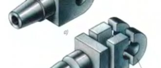
Removing the weld: 1 - parts to be welded; 2 - weld; 3 - material removed during processing
What GOST 16037-80 regulates
GOST 16037-80 was approved for use by the Decree of the USSR State Committee for Standards in the 1980s. It came into force in July 1981 and is still in force today. GOST replaced the previously existing standard in this industry 16037-70. In December 1990, the last and only changes were made to the document.
The scope of GOST regulation is welded joints of steel pipelines. It is required for use:
The mandatory nature of the standard means that all welders who begin welding steel pipes must take into account the provisions of the standard. Welded joints that are used for the production of pipes from strip and sheet material are excluded from the scope of regulation of the document.
When installing pipeline systems, one of the most common methods is manual welding, the production requirements for which are specified in GOST 16037-80. The full text of the document can be found here.
The safety of operation of pipeline systems largely depends on the quality of joints and seams.
With strict adherence to the requirements of the standard during the design and formation of the technological process and the actual execution of pipeline welds, the required level of quality is ensured.
Reinforcement of butt seams
Strengthening butt welding is complicated by the fact that most often its strengthening can lead to damage to the joint. For example, if the butt seam is made along the entire length or height of the metal components, then no reinforcement can be done at all. Surfacing will create excessive concentration at the melting point, due to which the surfacing can not only deteriorate, but also completely collapse. The thing is that the height of such welds is determined only by the elements being joined and taking into account the structure of the bead of the connection itself. This roller is the protrusion.
If the butt welding still needs to be processed, then you first need to relieve the tension with abrasive tools. After this, the area of the overlays is calculated, with the help of which the seam will be strengthened.
SNiP III-42-80: Assembly, welding and quality control of welded joints of pipelines
4.1. Before assembling and welding pipes, you must:
carry out a visual inspection of the surface of the pipes (in this case, the pipes should not have unacceptable defects regulated by the technical conditions for the supply of pipes);
clean the internal cavity of the pipes from soil, dirt, and snow that has gotten inside;
straighten or trim deformed ends and damaged pipe surfaces;
Clean the edges and adjacent inner and outer surfaces of the pipes to a width of at least 10 mm to bare metal.
When flash butt welding, you should additionally clean the end of the pipe and the belt under the contact shoes of the welding machine.
4.2. It is allowed to straighten smooth dents at the ends of pipes with a depth of up to 3.5% of the pipe diameter and deformed ends of pipes using shockless expanding devices. At the same time, on pipes made of steel with a standard tensile strength of up to 539 MPa (55 kgf/mm2), it is allowed to straighten dents and deformed pipe ends at positive temperatures without heating. At negative ambient temperatures, heating is required at 100-150°C. On pipes made of steel with a standard tensile strength of 539 MPa (55 kgf/mm2) and more - with local heating at 150-200 ° C at any ambient temperature.
Sections and ends of pipes with a dent depth of more than 3.5% of the pipe diameter or with tears must be cut out.
Repair by welding of nicks and burrs of chamfers up to 5 mm deep is allowed.
The ends of pipes with nicks and chamfers with a depth of more than 5 mm should be cut off.
4.3. The assembly of pipes with a diameter of 500 mm or more must be carried out on internal centralizers. Smaller diameter pipes can be assembled using internal or external centralizers. Regardless of the diameter of the pipes, the assembly of overlaps and other joints where the use of internal centralizers is impossible is carried out using external centralizers.
4.4. When assembling pipes with the same standard wall thickness, displacement of the edges is allowed by up to 20% of the pipe wall thickness, but no more than 3 mm for arc welding methods and no more than 2 mm for flash butt welding.
4.5. Direct connection on the route of pipes of different thicknesses of the same diameter or pipes with parts (tees, transitions, bottoms, bends) is allowed under the following conditions:
if the difference in wall thicknesses of joined pipes or pipes with parts (the maximum of which is 12 mm or less) does not exceed 2.5 mm;
if the difference in wall thicknesses of joined pipes or pipes with parts (the maximum of which is more than 12 mm) does not exceed 3 mm.
The connection of pipes or pipes with parts with a greater difference in wall thickness is carried out by welding between the joined pipes or pipes with parts of adapters or inserts of intermediate thickness, the length of which must be at least 250 mm.
With a thickness difference of up to 1.5 times the thickness, direct assembly and welding of pipes is allowed with special cutting of the edges of the thicker wall of the pipe or part. The design dimensions of the edges and welds must correspond to those shown in Fig. 1.
The displacement of the edges when welding pipes of different walls, measured along the outer surface, should not exceed the tolerances established by the requirements of clause 4.4 of this section.
Welding from the inside of the root of the weld of pipes with different walls with a diameter of 1000 mm or more along the entire perimeter of the joint is mandatory, in this case the welding layer must be cleaned of slag, electrode cinders and slag must be collected and removed from the pipe.
Rice. 1. Structural dimensions for cutting edges and welds of pipes of different thicknesses (up to 1.5 wall thickness)
4.6. Each joint must have the mark of the welder or team of welders performing the welding. At joints of steel pipes with a standard tensile strength of up to 539 MPa (55 kgf/mm2), marks must be applied mechanically or by surfacing. Joints of steel pipes with a standard tensile strength of 539 MPa (55 kgf/mm2) and more are marked with indelible paint on the outside of the pipe.
The marks are applied at a distance of 100-150 mm from the joint in the upper semicircle of the pipe.
4.7. Welding of any elements, except for cathode leads, in the locations of transverse annular, spiral and longitudinal factory welds is not allowed. If the project provides for welding elements to the pipe body, then the distance between the seams of the pipeline and the seam of the welded element must be at least 100 mm.
4.8. Direct connection of pipes with shut-off and distribution valves is permitted provided that the thickness of the welded edge of the fitting nozzle does not exceed 1.5 times the wall thickness of the pipe being joined to it in the case of special preparation of the edges of the fitting nozzle in the factory according to Fig. 2.
In all cases when the special cutting of the edges of the fitting pipe is not carried out in the factory, and also when the thickness of the welded edge of the fitting pipe exceeds 1.5 times the wall thickness of the pipe being joined to it, the connection should be made by welding a special adapter or adapter ring between the pipe being joined and the fittings .
Rice. 2. Preparation of wet fittings for fittings when directly connecting them to pipes
4.9. When welding a pipeline into a thread, the welded joints must be tied to the pickets of the route and recorded in the as-built documentation.
4.10. If there is a break in work for more than 2 hours, the ends of the welded section of the pipeline should be closed with inventory plugs to prevent snow, dirt, etc. from getting inside the pipe.
4.11. Circular joints of steel main pipelines can be welded using arc welding methods or flash butt welding.
4.12. It is allowed to carry out welding work at air temperatures down to minus 50°C.
When the wind exceeds 10 m/s, as well as during precipitation, it is prohibited to carry out welding work without inventory shelters.
4.13. Installation of pipelines should only be carried out on mounting supports. The use of soil and snow prisms for pipeline installation is not permitted.
4.14. Welders who have passed exams in accordance with the Rules for Certification of Welders of the Gosgortechnadzor of Russia, have certificates and have passed the tests regulated by the requirements of paragraphs are allowed to tack and weld main pipelines. 4.16—4.23 of this section.
4.15. The production of welded pipeline connecting parts (bends, tees, transitions, etc.) in the field is prohibited.
4.16. When performing welding work, each welder (team or link of welders in the case of welding a joint by a team or link) must (must) weld a permissible joint for pipes with a diameter of up to 1000 mm or half a joint for pipes with a diameter of 1000 mm or more under conditions identical to the welding conditions on route if:
he (they) started welding the main pipeline for the first time or had a break in his work for more than three months;
pipe welding is carried out from new steel grades or using new welding materials, technology and equipment;
The shape of the pipe ends for welding has been changed.
Rice. 3. Scheme of cutting samples for mechanical tests
4.17. The permissible joint is subjected to:
visual inspection and measurement, in which the weld must meet the requirements of paragraphs. 4.26; 4.27 of this section;
radiographic control in accordance with the requirements of clause 4.28 of this section;
mechanical tests of samples cut from a welded joint in accordance with the requirements of clause 4.19 of this section.
4.18. If the joint does not meet the requirements of paragraphs 4.26, 4.27, 4.32 of this section by visual inspection and measurement or by radiographic control, then welding and re-inspection of two other permissible joints are performed; If, during repeated inspection, unsatisfactory results are obtained at at least one of the joints, the team or individual welder is recognized as having failed the test.
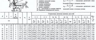
4.19. Mechanical tests involve checking tensile and bending samples cut from welded joints. The cutting pattern and the required number of samples for various types of mechanical tests must correspond to those shown in Fig. 3 and in table. 3.
Number of samples for mechanical testing
Source