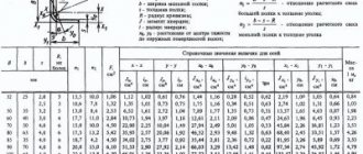
Shapes of geometric bodies
A part of any shape can be represented as a collection of individual geometric bodies.
For example, let's take a part (Fig. 159.a) and analyze its shape. Mentally dividing it into individual elements, we obtain the following geometric bodies (Fig. 159, b): 1 - a truncated straight circular cone with a cylindrical hole, 2 - a straight circular cylinder, 3 - a rectangular parallelepiped, 4 - two rectangular parallelepipeds with cylindrical holes, 5 - two hollow half-cylinders. To perform complex drawings, it is necessary to master methods for projecting individual geometric bodies, as well as points and lines located on the surface of these bodies.
Rice. 159
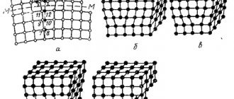
Geometric bodies bounded by flat polygons are called polyhedra (Fig. 160, a). These polygons are called faces, and their intersections are called edges. An angle formed by faces converging at one point - a vertex - is called a polyhedral angle.
Bodies of revolution are limited by surfaces that are obtained as a result of the rotation of a line around a fixed axis (Fig. 160, b and c). The line AB, which during its movement forms a surface, is called a generatrix. The most common bodies of rotation are cylinder, cone, ball, and torus.
Rice. 160
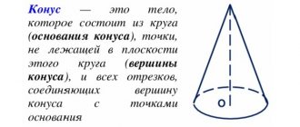
Round cone in geometry
Let us give a geometric definition of this figure. A circular cone is a surface that is formed by straight segments connecting all points of a certain circle with one single point in space. This single point must not belong to the plane in which the circle lies. If instead of a circle we take a circle, then this method also leads to a cone.
You may be interested in: Law College in Ivanovo: specialties, admissions committee, reviews
The circle is called the base of the figure, its circumference is the directrix. The segments connecting a point to a directrix are called generators or generators, and the point where they intersect is the vertex of the cone.
A round cone can be straight or inclined. Both figures are shown below in the figure.
You may be interested in: Thermophilic bacteria: benefits and harm for humans
The difference between them is this: if the perpendicular from the top of the cone falls exactly at the center of the circle, then the cone will be straight. For him, the perpendicular, which is called the height of the figure, is part of its axis. In the case of an inclined cone, the height and axis form some acute angle.
Due to the simplicity and symmetry of the figure, we will further consider the properties of only a straight cone with a round base.
Prism projections
The construction of projections of a regular straight hexagonal prism (Fig. 161) begins with the implementation of its horizontal projection - a regular hexagon. From the vertices of this hexagon, vertical communication lines are drawn and a frontal projection of the lower base of the prism is built. This projection is represented by a horizontal line segment. From this straight line upward, the height of the prism is plotted and a frontal projection of the upper base is constructed. Then the frontal projections of the ribs are drawn - segments of vertical straight lines equal to the height of the prism. The frontal projections of the anterior and posterior ribs coincide. Horizontal projections of the side faces are depicted as straight segments. The front side face 1243 is depicted on the V plane without distortion, and on the W plane as a straight line. Frontal and profile projections of the remaining side faces are depicted with distortion.
In the drawing, the x, y and z axes are not shown, which makes the drawing simpler.
Rice. 161
The construction of projections of an inclined prism is somewhat more complicated.
Let's consider the procedure for constructing projections of an inclined hexagonal prism.
1. A prism, the base of which lies on the plane H, is inclined to this plane at angle α (Fig. 162, a). The edges of the prism are parallel to plane V, i.e. are frontal.
First, a horizontal projection of the base of the prism is constructed, which is projected onto the H plane without distortion (regular hexagon). The frontal projection of the base is a straight line segment parallel to the x-axis.
From points 1′, 2′, 3′ of the frontal projection of the base, direct projections of the ribs are drawn at an angle α to the x-axis and the actual length of the side edge of the prism is plotted on them.
Construct a frontal projection of the upper base of the prism in the form of a straight line segment equal and parallel to the frontal projection of the lower base.
From points 1, 2, 3, 4. 5. 6 of the horizontal projection of the lower base, straight lines are drawn - projections of the ribs - parallel to the x-axis and six points are found on them using vertical connection lines - horizontal projections of the vertices of the upper base of the prism.
2. A straight regular hexagonal prism is inclined at an angle α to the plane H. The base of the prism is inclined to the plane H at an angle β (Fig. 162, b).
In this case, it is necessary to first construct a frontal projection of the base. This projection is a segment equal to the distance between the parallel sides of the hexagon. If this segment is divided in half and a connection line is drawn from its middle, then points 2 and 5 will be located on it - horizontal projections of the vertices of the base of the prism. The distance between points 2, 5 is equal to the actual distance between the vertices of the base of the prism. Since the horizontal projections of sides 16 and 34 represent their actual lengths, taking advantage of this circumstance, it is possible to construct a completely horizontal projection of the base.
The further construction process shown in Fig. 162, b, similar to that shown in Fig. 162, a.
Rice. 162
In complex drawings of objects, it is often necessary to construct projections of lines and points located on the surface of these bodies, having only one projection of a line or point. Let's consider the solution to this problem.
A complex drawing of a quadrangular right prism and a frontal projection a' of point A are given.
First of all, you need to find in the complex drawing two projections of the face on which point A is located. In the complex drawing you can see (Fig. 163, a) that point A lies on the face of prism 1265. The frontal projection a' of point A lies on the frontal projection 1' 2'6'5' prism faces. The horizontal projection 1562 of this face is segment 56. On this segment there is a horizontal projection a of point A. The profile projection of the prism and point A is constructed using communication lines.
Using the existing complex drawing of the prism, you can perform its isometric projection along the coordinates of the vertices. To do this, first build the lower base of the prism (Fig. 163, b), and then the vertical ribs and the upper base (Fig. 163, c).
Using the coordinates m and n of point A, taken from a complex drawing, it is possible to construct an axonometric projection of this point.
Rice. 163
Learning to draw correct proportional cones
The cone is the basis of many objects: firs, many wind instruments, horns, lamp shades and so on. Therefore, it is so important to master this figure in the initial stages of drawing courses. In addition, geometric figures help a novice artist understand the laws of perspective and learn how to show volume in a drawing.
Drawing geometric shapes is one of the components of the curriculum of all art schools. No artist can do without the ability to depict them, regardless of what style he plans to work in in the future. Usually the course begins with them, and only then students move on to more complex materials - to drawing rosettes, capitals, faces and human figures. Every artist should also be able to easily apply shading with a pencil and create volume.
If you are going to enter an art university, you will have to take a creative exam. The image of a geometric body is one of his tasks. Despite the apparent simplicity of drawing a cone, not everyone succeeds in drawing it on the first try without errors. Therefore, it will be better if you practice enough before the entrance test. To successfully pass, applicants need to depict more than one body of rotation and hone their skills in order to feel confident and free during the test itself.
The school-studio “Master of Drawing” by K. E. Arutyunova has been preparing applicants for admission to the main art universities in Moscow for several years now. Enough time is devoted to drawing geometric figures and bodies of revolution in the courses. An individual approach is applied to each student here, taking into account his level of preparation and the amount of time before the exam. The teacher notes all the student’s mistakes and explains them clearly and gives advice on correction. Sign up for courses by phone or through the form on the website.
Pyramid projections
The construction of projections of a triangular pyramid begins with the construction of a base, the horizontal projection of which is a triangle without distortion (Fig. 164, a). frontal projection of the base - a segment of a horizontal straight line.
From the horizontal projection of point s (the vertex of the pyramid), a vertical connection line is drawn, on which the height of the pyramid is plotted from the x axis and the frontal projection s' of the vertex is obtained. By connecting point s' with points 1′, 2′ and 3′, frontal projections of the edges of the pyramid are obtained.
Horizontal projections of the edges are obtained by connecting the horizontal projection of point s with the horizontal projections of points 1, 2 and 3.
Let, for example, be given a frontal projection a' of point A, located on the face of the pyramid 1s2, and you need to find another projection of this point. To solve this problem, we draw an arbitrary auxiliary line through a' and continue it until it intersects with the frontal projections of the 1's' and 2's' edges at points n' and m'. Then we draw connection lines from points n' and m' to the intersection with the horizontal projections 1s and 2s of these edges at points n and m. By connecting n with m, we obtain a horizontal projection of the auxiliary straight line, on which, using the connection line, we find the desired horizontal projection a of the point And the profile projection of this point is found along the communication lines.
Another way to solve the problem of constructing the projection of a point from its given projection is shown in Fig. 164, b. Given a quadrangular regular pyramid. Through a given frontal projection a' of point A, an auxiliary straight line is drawn, passing through the top of the pyramid and located on its edge. The horizontal projection ns of the auxiliary line is found using a communication line. The required horizontal projection a of point A is located at the intersection of the connection line drawn from point a' with the horizontal projection ns of the auxiliary straight line.
The frontal dimetric projection of the pyramid in question is performed as follows (Fig. 164, c).
First, they build the base, for which the length of diagonal 13 is plotted along the x-axis, and half the length of diagonal 24 is plotted along the y-axis. From the point O of the intersection of the diagonals, the z-axis is drawn and the height of the pyramid is plotted on it. The vertex S is connected to the vertices of the base by straight lines - edges.
The frontal dimetric projection of point A, located on the edge of the pyramid, is constructed according to coordinates that are taken from the complex drawing. From the coordinate line O along the x axis, the xA coordinate is plotted, from the end parallel to the y axis - half of the yA coordinate and from the end of this coordinate parallel to the z axis - the third coordinate zA. The construction of point B, located on the edge of the pyramid, is simpler. From point O along the x axis, the xB coordinate is plotted and from its end a straight line is drawn, parallel to the z axis, until it intersects with the edge of the pyramid at point B.
Rice. 164
Cylinder projections
The lateral surface of a right circular cylinder is obtained by rotating the segment AB of the generatrix around an axis parallel to this segment. In Fig. 165, and an isometric projection of the cylinder is presented.
The construction of horizontal and frontal projections of the cylinder is shown in Fig. 165, b and c.
The construction begins with an image of the base of the cylinder, i.e. two projections of a circle (Fig. 165, b). Since the circle is located on the H plane, it is projected onto this plane without distortion. The frontal projection of the circle is a segment of a horizontal straight line equal to the diameter of the base circle.
After constructing the base, two outline (outer) generatrices are drawn on the frontal projection and the height of the cylinder is plotted on them. Draw a segment of a horizontal straight line, which is the frontal projection of the upper base of the cylinder (Fig. 165, c).
Rice. 165
Determining the missing projections of points A and B located on the surface of the cylinder from given frontal projections in this case does not cause any difficulties, since the entire horizontal projection of the side surface of the cylinder is a circle (Fig. 166.a). Consequently, horizontal projections of points A and B can be found by drawing vertical connection lines from given points a' and b' until they intersect with the circle at the desired points a and b.
Profile projections of points A and B are also constructed using vertical and horizontal communication lines.
An isometric projection of the cylinder is drawn as shown in Fig. 166, b.
In isometry, points A and B are plotted using coordinates. For example, to construct point B from the origin of coordinates O, the coordinate xB = n is laid out along the x axis, and then a straight line is drawn through its end, parallel to the y axis, until it intersects with the contour of the base at point 1. From this point, a straight line is drawn parallel to the x axis, to which plots the coordinate xB = h1 of point B.
Rice. 166
Getting a shape using rotation
Before moving on to considering the development of the surface of a cone, it is useful to learn how this spatial figure can be obtained using rotation.
Suppose we have a right triangle with sides a, b, c. The first two of them are legs, c is the hypotenuse. Let's place the triangle on side a and begin to rotate it around side b. The hypotenuse c will describe a conical surface. This simple technique for obtaining a cone is shown in the diagram below.
Obviously, leg a will be the radius of the base of the figure, leg b will be its height, and hypotenuse c corresponds to the generatrix of a round right cone.
Projections of cones
A clearer image of a straight circular cone is shown in Fig. 167, a. The lateral surface of the cone is obtained by rotating the segment BS around the axis intersecting the segment at point S. The sequence of constructing two projections of the cone is shown in Fig. 167, b and c. First, two projections of the base are constructed. The horizontal projection of the base is a circle. The frontal projection will be a segment of a horizontal straight line equal to the diameter of this circle (Fig. 167, b). On the frontal projection, a perpendicular is drawn from the middle of the base and the height of the cone is plotted on it (Fig. 167, c). The resulting frontal projection of the top of the cone is connected by straight lines to the ends of the frontal projection of the base and a frontal projection of the cone is obtained.
Rice. 167
If one projection of point A is given on the surface of the cone (for example, the frontal projection in Fig. 168, a). then the other two projections of this point are determined using auxiliary lines - a generatrix located on the surface of the cone and drawn through point A, or a circle located in a plane parallel to the base of the cone.
In the first case (Fig. 168. a) a frontal projection s'a'f ' of the auxiliary generatrix is carried out. Using a vertical connection line drawn from point f, located on the frontal projection of the base circle, find the horizontal projection sf of this generatrix, on which, using the connection line passing through a', find the desired point a.
In the second case (Fig. 168. b), the auxiliary line passing through point A will be a circle. located on a conical surface and parallel to the plane H. The frontal projection of this circle is depicted as a segment b'c' of a horizontal straight line, the size of which is equal to the diameter of the auxiliary circle. The required horizontal projection a of point A is located at the intersection of the connection line drawn from point a' with the horizontal projection of the auxiliary circle.
If the given frontal projection b' of point B is located on the contour (outline) generatrix SK, then the horizontal projection of the point is found without auxiliary lines (Fig. 168. b).
In an isometric projection, point A, located on the surface of the cone, is plotted using three coordinates (Fig. 168, c): xA = n, yA = m, zA = h. These coordinates are sequentially plotted in directions parallel to the isometric axes. In the example under consideration, the coordinate xA = n is plotted from point O along the x axis; from its end, parallel to the y-axis, a straight line is drawn, on which the coordinate yA = m is plotted; From the end of the segment equal to m, a straight line is drawn parallel to the z axis, on which the coordinate zA = h is plotted. As a result of construction, we obtain the required point A.
Rice. 168
Correct drawing of a cone in pencil - volume
In order to give our cone volume, we should add light and shadow. We mark the boundary of light and shadow, find the lightest area. The cone contains the following shadow areas:
- semitone;
- light;
- glare;
- light;
- semitone;
- shadow;
- glare
It is this distribution of light and shadow that can make the cone look three-dimensional. The center of the highlight depends on where the light is coming from.
The strokes follow the form, while there are no clear boundaries between light and shadow.
During classes, our teachers tell you how to correctly create a cone drawing, and conduct lectures and practical groups.
Did you find apk for android? You can find new Free Android Games and apps.
Projections of a ball
In Fig. 169, and half of a ball is depicted; the spherical surface of this ball is formed by the rotation of a quarter of a circle AB around the radius AO.
The projections of this figure are shown in Fig. 169, b. The horizontal projection is a circle of radius equal to the radius of the sphere, and the frontal projection is a semicircle of the same radius.
If point A is located on a spherical surface (Fig. 169, c), then the auxiliary line b'c', drawn through this point parallel to the horizontal projection plane, is projected onto the horizontal projection plane by a circle. On the horizontal projection of the auxiliary circle, the desired horizontal projection a of point A is found using the connection line.
The diameter of the auxiliary circle is equal to the frontal projection b'c'.
Rice. 169
Projections of the ring and torus
The surface of the circular ring (Fig. 170, a) is formed by the rotation of the generatrix of the circle ABCD around the OO1 axis.
A torus is a surface formed by the rotation of a part of a circular arc, which is the generatrix, around the OO1 axis, located in the plane of this circle and not passing through its center.
Rice. 170
In Fig. 171, a and b, two types of torus are shown. In the first case, the generating arc of a circle of radius R is spaced from the axis of rotation at a distance less than radius R, and in the second case - greater.
In both cases, the frontal projections of the torus represent the actual appearance of two generating arcs of a circle of radius R, located symmetrically relative to the frontal projection of the axis of rotation. The profile projections of the torus will be circles.
A circular ring (or an open torus) has a horizontal projection in the form of two concentric circles, the difference in radii of which is equal to the thickness of the ring or the diameter of the generatrix of the circle (Fig. 170, b). The frontal projection is limited on the right and left by arcs of semicircles of the diameter of the generatrix.
Rice. 171
In the case when point A lies on the surface of a circular ring and one projection is given, to find the second projection of this point, an auxiliary circle is used, passing through this point A and located on the surface of the ring in a plane perpendicular to the axis of the ring (Fig. 172).
If a frontal projection a' of a point A lying on the surface of the ring is given, then to find its second projection (in this case, profile) through a', draw the frontal projection of an auxiliary circle - a segment of a vertical straight line b'c'. Then a profile projection b"c" of this circle is constructed and point a" is found on it using a communication line.
If a profile projection a" of point D located on the surface of this ring is given, then to find the frontal projection of point D through d" a profile projection of an auxiliary circle of radius O"d" is carried out. Then, horizontal connection lines are drawn through the upper and lower points e" f" of this circle until they intersect with the frontal projections of the generatrix of the circle of radius r and points e' and f' are obtained. These points are connected by a vertical line, which represents the frontal projection of the auxiliary circle (it will be invisible). Drawing a horizontal connection line from point d" to the intersection with straight line e'f ', we obtain the desired point d'.
The same construction techniques are applicable for points located on the surface of the torus.
Rice. 172