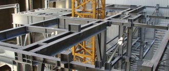
Metal welded I-beams have been used for the construction of structures and floors for a long time. But until this time in Russia its use was strictly limited to the sphere of industrial construction, i.e. when truly grandiose structures are erected, which should not care about anything.
And only in recent years have such types of I-beams begun to appear that can actually be used in the construction of new houses of an ordinary residential building. Are you thinking about just such an overlap? Then we will help you learn all the features of its manufacture!
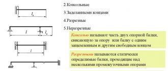
Calculation of beam deflections
Let's see how to use the initial parameters method using the example of a simple beam, which is loaded with all kinds of loads, in order to maximally cover all the subtleties of this method:
Support reactions
To make the calculation, you need to know all the external loads acting on the beam, including the reactions occurring in the supports.
If you don’t know how to determine reactions, then I recommend studying this material, where I tell you how they are determined using the example of this beam:
Distributed load
The initial parameters method, which we will use a little later, only works when the distributed load reaches the rightmost section, the one farthest from the origin of the coordinate system. Specifically, in our case, the load breaks and such a design scheme is unacceptable for further calculations.
If the load were applied like this:
Then we could immediately begin calculating displacements. We will need to use one tricky trick - introduce additional loads, one of which will continue the existing load q, the other will compensate for this artificial continuation. Thus, we obtain an equivalent design scheme, which can already be used in the calculation using the initial parameters method:
Let's proceed directly to the calculation of the beam deflection itself. Let's consider the most interesting section in the middle of the span; it is obvious that this section will bend the most and when calculating the rigidity of such a beam, this particular section would be calculated. Let's call it the letter C:
We write down the boundary conditions relative to the coordinate system. Taking into account the method of securing the beam, we fix that the deflections at points A and B are equal to zero, and the distances from the origin to the supports are important:
\
\
We write the equation of the initial parameters method for section C:
\
The product of the beam stiffness EI and the section deflection C will be the sum of the product EI and the section deflection at the origin of the coordinate system, that is, section A:
\
Let me remind you that E is the modulus of elasticity of the first kind, depending on the material from which the beam is made, I is the moment of inertia, which depends on the shape and dimensions of the cross section of the beam. The angle of rotation of the cross section at the origin of the coordinate system is also taken into account, and the angle of rotation is additionally multiplied by the distance from the section in question to the origin of coordinates:
\
Accounting for external load
And finally, you need to take into account the external load, but only that which is located to the left of the section C under consideration. There are several features here:
Concentrated forces and distributed loads that are directed upward, that is, coincide with the direction of the y-axis, are written in the equation with a plus sign. If they are directed in the opposite direction, respectively, with a minus sign:
Moments directed clockwise are positive, counterclockwise are negative:
All concentrated moments need to be multiplied by the fraction:
\
All concentrated forces need to be multiplied by the fraction:
\
The beginning and end of distributed loads must be multiplied by a fraction:
\
Where did these numbers and degrees come from? All these things follow when integrating the differential equation of the elastic line of a beam; in the method of initial parameters, all these conclusions are omitted, that is, it is, as it were, a simplified and universal method.
Deflection formulas
Taking into account all the rules described above, we write the final equation for section C:
\
Therefore, in order to find the deflection, we will compose a second equation for section B, from which we can determine the angle of rotation of section A. At the same time, we will fix the material passed through:
\
Let's simplify the equation:
\
Expressing the angle of rotation:
\
We substitute this value into our first equation and find the desired displacement:
\
Calculation of deflection
The value was obtained in a general form, since initially they did not specify what cross-section the beam being calculated has. Let's imagine that the metal beam has an I-beam cross section of No. 30. Then:
\
Fastening units for welded I-beams
So, now let's understand the support nodes of metal I-beams. Their support on a steel column (support) can be rigid or hinged, that is, movable.
The connection of finished welded beams to each other during the installation process can be done in two ways:
- The first of which is that the I-beams are first welded to a special plate, and welding is carried out along the contour of the profile using fillet welds. The advantage of this particular method is that it is not necessary to separate the edges of the beams.
- The second method is to use overlays that are mounted symmetrically to the longitudinal axis, cut and welded with oblique seams. Thanks to this, it is possible to avoid problems with applying a weld along the entire side of the overlay. This welding method is suitable for structures with little future load, i.e. just for the construction of a private residential building.
- Welded beams can also be connected using a bolted connection - this is a detachable method, which is necessary to ensure that there is no residual stress in the structure, and the floor structure itself is resistant to shock and vibration loads. And also when it is not possible to invite professional welders.
Here is an interesting video comparing both types of beam connections:
As you already understand, in most cases, a metal welded beam is connected by welding, less often with bolts and even less often with rivets. All this directly affects the cost of installing such beams.
As for rivets, working with them is the most labor-intensive, although sometimes, unfortunately, you cannot do without such elements. For example, if the beam will be constantly subject to vibration (such equipment will be used), then it cannot be connected too rigidly to the structure.
If you are going to connect the entire metal structure with bolts, then:
- You will need normal and high precision fasteners. Only in places where there will be a shear load, bolts of normal or rough accuracy should not be used.
- You will need to make gaps in the beam in advance (or order something similar at the factory) so that the outer diameter of the hole itself is only 2-3 mm larger than the outer diameter of the bolt. This design will be resistant to deformation, and assembly is generally simpler.
- Precision bolt connections are well suited for hard-to-reach areas where riveted connections are not possible. But here the diameter of the holes needs to be increased by 0.3 mm so that the fasteners can easily withstand the upcoming load.
So, let’s now consider such an important stage as welding the main beam with the secondary one. Do everything step by step:
- Step 1. At the top of the main beam, make a triangular cutout of the exact size.
- Step 2. Weld the trim to the bottom of the main beam.
- Step 3. Make cuts in the bottom of the auxiliary beam that will be equal to half the width of the bottom of the main beam.
- Step 4. Now the top of the secondary beam needs to be formed into a triangular shape, the same as the top of the main beam was cut.
- Step 5. Next, we carry out installation: first the main beam, then the secondary one, and all this using the method of using an overlay.
- Step 6. And finally, the last stage is the installation of the junction of the upper parts and walls, where the overlay is also welded to the lower parts of the beams.
You can also fasten metal I-beams to each other using the bolt connection method. This method is necessary when from time to time you have to install or dismantle a specific unit. The advantage of such a connection is that there will be no residual stress in the structure. Which in itself is good, because then the ceiling will be more resistant to shock loads, and, in addition, you will not need to invite a professional welder to create the unit.
Rigid node: for static loads
Those. the beam can rest on top, directly on the center of the column profile, or the beam can be attached to the side. Then only a compressive load arises in the column, but the action of all forces occurs, so it has to be made stronger and more reliable, and this is an overconsumption of metal.
Sometimes it is also necessary to lay two beams across a span, then they are connected to each other using bolts and plates are installed between the two ribs. It is important to remember that metals are subject to thermal expansion due to temperature changes, and therefore you need to leave a small distance for their unnoticeable movement.
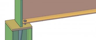
To transmit transverse pressure force, the rib of the beam is placed so that during installation it is directly above the column flange. In this case, the beam is connected to the column using a special overhead plate, and preferably immediately on both sides. But in such a way as not to create too tight a knot.
Here is a good example of how welded beams are combined on two spans so as not to create point stress on the intermediate floor wall:
To create a rigid beam connection, you will need a bolted or welded connection:
Hinge joint: for dynamic loads
Now about the hinged support of the welded beam. It is created using a support rib on the support table, where the entire load will be transferred. You will need to make the table itself from sheet steel.
Weld a table on three sides of the beam and make its width 2-3 cm larger than the rib of the beam. So the supporting edge should lie completely on the supporting table.
Types of floor structures
There are several types of attic floors with wooden beams. Each of them has its own purpose and its own pros and cons.
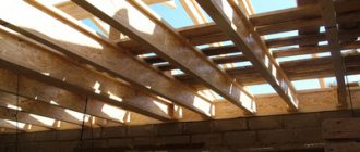
As for frame houses, the floors in them are recommended using the “platform” system. That is, after installing the walls, beams are laid and a certain platform is created, as it were, and a working foundation for the future floor of the attic at the same time
It is important here not to put unnecessary pressure on fragile walls, so the attic covering will also not be designed for a piano in the corner
In this case, the beams are installed on a strapping beam, which is used as a power plate:
But in a house with walls made of logs or timber, according to the rules, a rigid shield is installed as an attic floor, which, when the walls shrink, will smoothly lower with them, and always evenly.
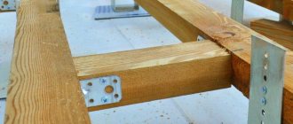
Prefabricated wooden floors should be highlighted as a separate type of attic floors. Their main feature is the use of special fasteners, which are made of galvanized steel. Their thickness and quality are calculated depending on the level of future loads on the floor.
Standard attic floors on beams with beams and wooden joists appeared at the end of the 20th century, and after them floors made of wide boards became more fashionable.
Today, special ready-made companies for arranging attic floors are also in fashion. In fact, this is not a new thing in the construction market; such companies appeared at the end of the 16th century and found their rebirth at the end of the 20th century. Canadian companies that were involved in construction developed special calculation programs for such companies and their exact shapes with assembly lines.
In our country, new types of wooden floors are beginning to appear, which until now were popular only abroad. These are light wooden floors. They are relevant for private construction, when a fairly light wooden frame is used as a system.
The essence of the overlap is that “ribs” are installed every 30-60 centimeters, and they are covered with sheathing. Wooden beams with a height of about 20 and 28 centimeters, a thickness of 45 centimeters, and a length of up to 5 meters are taken as “ribs”. They are made from natural wood and connected with special bundles of boards, covered with chipboard or fiberboard sheathing.
Therefore, we highlight quick and simple installation as the main advantages of a ribbed attic floor. Of the minuses: the need for treatment with a fire retardant, less strength and low sound insulation properties. And, of course, such boards are more sensitive to sudden fluctuations in humidity and temperature. And also, if a fungus or some insect decides to eat such a ceiling in a few years, it will eat it much faster than thick beams.
From below, this structure is covered with a suspended ceiling made of plasterboard slabs. Mineral wool is placed between the ribs on top. It is this that will provide fire resistance and sound insulation to the entire wooden floor.
Ribbed attic floors are much cheaper than beam floors - this is quite reasonable and rational if you do not insulate a non-residential premises and make a residential attic out of it. Then you don’t have to worry about the load-bearing capacity of such a foundation. The only negative is that beams are more common for Russian houses, and the ribbed ceiling is almost no different in appearance from the monolithic one. Therefore, in Russian houses, ribbed beam attic floors are more often installed.
The beam for constructing such an attic floor must be taken in a rectangular shape, and strictly, and not in a diamond shape. And be sure, when buying such timber, take with you the most common school ruler, because it often happens that many people are going to build a floor from 15x15 cm timber, but in the end they are built from 14x14 cm timber. And then, on your site, be sure to prepare a place for storage such timber and its processing.
By the way, today many even install ordinary timber in a wooden floor on its edge. The fact is that even a ruler, no matter what material it is made of, easily bends along its entire length, but if you place it edgewise, it will be almost impossible to bend it:
Lay a finished floor on the rough floor made of boards, and install a suspended ceiling underneath. But often the wooden floor of the attic is left without additional finishing on purpose, in view of the interior design concept, but then all its details are done very carefully and even with a decorative slope:
The suspended ceiling itself imparts a certain rigidity to the ribbed ceiling.
About the new technology of private housing construction
Today, the production of welded I-beams has been launched throughout the country, and is in demand even in private housing construction. And all this is due to new design and architectural solutions! Their modern volumetric planning projects require special quality load-bearing frames and reliable ceilings, which will be most effective for large spans - from 7 meters.
You've probably noticed how country cottage houses and similar buildings differ in their appearance from the original Russian hut. Now imagine how different their architecture and construction principles are! That is why steel I-beams today have become actively used to cover spans from 4 to 18 m, and both carbon and low-alloy steel are used for their production, which guarantees the required qualities and strength.
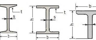
For the manufacture of such beams there is even a GOST and the necessary certificates. Tangential stresses are taken up by solid walls, and compressive and tensile stresses are evenly distributed along the length. To make it more clear to you, the role of such a vertical wall is essentially the same as that of a zigzag lattice in a metal truss. Although at first glance such beams do not look too strong or monolithic:
Necessary explanations for calculations
- Height and width determine the cross-sectional area and mechanical strength of the beam.
- Wood material: pine, spruce or larch - characterizes the strength of the beams, their resistance to deflection and fracture, and other special performance properties. Usually preference is given to pine beams. Larch products are used for rooms with a humid environment (baths, saunas, etc.), and spruce beams are used in the construction of inexpensive country houses.
- The type of wood affects the quality of the beams (as the grade increases, the quality deteriorates). 1st grade. On each one-meter section of timber, on any side there can be healthy knots measuring 1/4 of the width (face and edge), and 1/3 of the width (edge). There may also be rotten branches, but their number should not exceed half of the healthy ones. It should also be taken into account that the total dimensions of all knots in an area of 0.2 m must be less than the maximum width size. The latter applies to all grades when it comes to load-bearing beam structures. There may be plate cracks measuring 1/4 of the width (1/6 if they extend to the end). The length of through cracks is limited to 150 mm; first grade timber can have end cracks up to 1/4 of the width. The following wood defects are allowed: tilting of the fibers, tilt (no more than 1/5 of the side area of the beam), no more than 2 pockets, one-sided growth (no more than 1/30 in length or 1/10 in thickness or width). Grade 1 timber may be affected by fungus, but no more than 10% of the lumber area; rot is not allowed. There may be a shallow wormhole on the wane parts. To summarize the above: the appearance of such timber should not cause any suspicion.
- 2nd grade. Such a beam can have healthy knots measuring 1/3 of the width (face and edge), and 1/2 of the width (edge). For rotten knots, the requirements are the same as for grade 1. The material may have deep cracks up to 1/3 the length of the timber. The maximum length of through cracks should not exceed 200 mm; there may be cracks at the ends up to 1/3 of the width. Allowed: inclination of fibers, heel, 4 pockets per 1 m., sprouting (no more than 1/10 in length or 1/5 in thickness or width), cancer (extending up to 1/5 of the length, but not more than 1 m) . Wood can be affected by fungus, but not more than 20% of the area of the material. Rot is not allowed, but there can be up to two wormholes in a 1 m area. To summarize: grade 2 has borderline properties between 1 and 3, and generally leaves a positive impression upon visual inspection.
- 3rd grade. Here the tolerances for defects are greater: the timber can have knots measuring 1/2 the width. Face cracks can reach 1/2 the length of the lumber; end cracks measuring 1/2 the width are allowed. For grade 3, it is allowed to bend the fibers, tilt, pockets, core and double core, sprouting (no more than 1/10 in length or 1/4 in thickness or width), 1/3 of the length may be affected by cancer, fungus, but not rot are allowed. The maximum number of wormholes is 3 pcs. per meter To summarize: grade 3, even to the naked eye, does not stand out as the best quality. But this does not make it unsuitable for the manufacture of floors on beams. For more information about the varieties, read GOST 8486-86 Softwood lumber. Technical specifications;
Our online calculator will allow you to calculate the parameters of wooden beams and select the optimal floor configuration.
Initial parameters method
The initial parameters method is a fairly universal and simple method. Using this method, you can write a formula to calculate the deflection and rotation angle of any section of a beam of constant stiffness (with the same cross-section along the length).
The initial parameters are understood as already known movements:
- deflections in supports are zero;
- in a rigid embedment, the deflection and rotation angle of the section are zero.
Taking into account these properties, they are also called boundary conditions, displacements in other parts of the beam are determined.
Types of Wood Beams
Wooden beams vary in size, cross-section, production method and type of wood from which they are made. The reliability and strength of the structure depends on the choice of wooden beams. Depending on the distance between the walls and the expected load for the floors, use a board or beam made of solid wood, or glued products.
Types of wooden beams
Solid beams
Beams made from solid wood are less durable than glued or I-beams. Therefore, their length should not exceed 6 meters. Often, to increase strength, builders on site pair boards. They are tightened with bolts and nuts with rubber or plastic gaskets that prevent moisture from entering and rust forming on the fasteners.
Glued laminated timber
Glued laminated timber is made by gluing several parts together. Beams made of this material can withstand high loads, so they can be used in the construction of floors up to 14 meters long. From such timber you can make bent floors for arches.
Such products also have disadvantages. Low-quality lumber may be used in manufacturing, so the beam floor may shrink over time. In addition, glued beams are much more expensive than solid ones. In order to more efficiently use the funds allocated for construction, you need to correctly calculate the load and length of the beams.
Glued laminated timber with a similar cross-section to conventional timber has greater strength
Floor beams are made from coniferous wood, but oak, acacia, maple and other trees are also often used. The main condition necessary for the strength of the structure is humidity no more than 12–14%. Types of some products are shown in the table below.
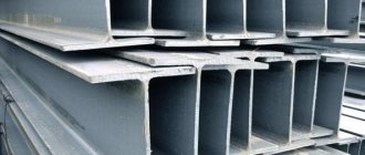
I-beams
The advantages of I-beams are versatility of use, ease of installation and high strength. They retain their parameters under heavy loads without auxiliary structures for reinforcement.
I-beam device
I-beams are made using well-dried planed or laminated timber, durable glued waterproof plywood or OSB boards, based on fire-resistant and moisture-resistant glue. Therefore, an I-beam wooden beam does not require impregnation with special compounds and can be easily sawed. However, due to the complex manufacturing technology, they are rarely used for flooring.
I-beams made of OSB (OSB)
Connecting I-beams to each other
All types of products have their own assortment. An assortment is a selection of various finished products by brand, profile or size. Often the table will include additional information about strength, weight, etc.
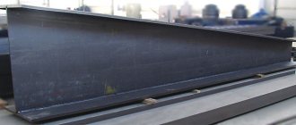
What is a welded I-beam?
According to their type of section, I-beams today are usually divided into rolled or composite, which are also called welded. A welded I-beam is a special type of shaped rolled metal in the form of an inclined or horizontal beam. Today it is made from carbon and low-alloy steel, always of high quality.
Let's list the main advantages of welded I-beams:
- Cover large spans with significant loads.
- Ideally redistribute horizontal and vertical loads.
- They work well in bending due to the rigidity of the beam profile.
- They do not burn and do not lose their load-bearing capacity when heated even at fairly high temperatures.
- Resistant to biological influences.
- Excellent for the construction of prefabricated building structures.
- They allow a significant reduction in the weight of the entire structure compared to hot roots.
- They are also manufactured with a completely asymmetrical cross-section.
That is why such welded beams are used today in the construction of residential buildings, industrial complexes, and even bridges and tunnels. It would seem that such a beam would be too heavy for private house construction, but in fact, the use of steel I-beams can ultimately reduce the total weight of load-bearing structures. But remember that in relation to the ceiling made of welded steel I-beams, there are strict requirements:
What does incorrect calculation of floor joists for a frame house lead to?
The Internet is full of reviews about how floors in frame houses sag, creak and spring. There are a lot of tearful texts and videos on this topic.
Thanks to this profanity and populism, a widespread opinion has already formed that a frame house is bad.
Despite the fact that there are a lot of negative reviews, they do not contain one important detail - a true story that in fact these frames were built either by defectors from advertised companies, or by the hands of crooks from crews found somewhere unknown
Just as there is no clear explanation of what to pay attention to when installing the floor of a frame house as a whole and what parameters of the lag for the floor of a frame house are important in particular. Many people try to do the right thing, but... ...for example, I don’t like everything in these videos
To put it mildly…
...for example, I don’t like everything in these videos. To put it mildly…
Actually, this article will show the simplest way to calculate floor joists and talk about the main parameter that affects the quality and reliability of the floors of a frame house.
Important
It should be noted that logs (beams) are just one of the components of the floor structure of a frame house. In a high-quality ceiling, all structural elements must be used and all of them must be matched to each other in terms of parameters.
General information on calculation methodology
In most cases, single-span beams are used in low-rise construction.
They can be in the form of logs, boards or beams. The length of the elements can vary over a wide range. In most cases, it directly depends on the parameters of the structure that you are going to build.
Attention! The calculator for calculating beams for deflection presented at the end of the page will allow you to calculate all the values with minimal time. To use the program, just enter basic data
The role of load-bearing elements in the structure is performed by wooden blocks, the section height of which ranges from 140 to 250 mm, the thickness is in the range of 55–155 mm. These are the most commonly used parameters when calculating the load-bearing capacity of wooden beams.
Very often, professional builders use a cross beam installation scheme to strengthen the structure. It is this technique that gives the best results with minimal expenditure of time and materials.
If we consider the length of the optimal span when calculating the load-bearing capacity of wooden beams, then it is best to limit the architect’s imagination in the range from two and a half to four meters.
Attention! The best cross-section for wooden beams is considered to be an area whose height and width have a ratio of 1.5 to 1
Classic mistakes
Engineers who do not have the proper experience often make some mistakes when calculating beams, namely:
A cross-section that is too small, even if it meets the strength conditions, can bend beyond the standard values, which is why the ceiling will no longer meet operational requirements.- On the contrary, too large a cross-section will lead to excessive consumption of materials and increased construction costs.
- Incorrectly selected beam clamping will affect the calculation result.
- When calculating, it is necessary to reduce all units to a single module, otherwise, the result will be far from the truth.
In order to avoid making typical mistakes, you should perform the calculation in accordance with the algorithm and record all intermediate results. After performing the calculation, you should check the result several times. If in doubt, it is better to compare the selected beam section with similar examples.
Drawing up a design diagram of a beam
In order to draw up a calculation scheme, you do not need much knowledge. To do this, it is enough to know the size and shape of the cross-section of the element, the span between the supports and the method of support. The span is the distance between two supports. For example, you use beams as supporting floor beams for the load-bearing walls of a house, between which there are 4 m, then the span will be equal to 4 m.
When calculating the deflection of a wooden beam, they are considered to be simply supported structural elements. In the case of calculation, a circuit with a load that is distributed evenly is adopted. It is denoted by the symbol q. If the load is concentrated in nature, then a diagram with a concentrated load, denoted F, is taken. The magnitude of this load is equal to the weight that will exert pressure on the structure.
Ways to perform deflection calculations and tests
The reason why SNiPs establish such draconian restrictions is simple and obvious. The smaller the deformation, the greater the margin of strength and flexibility of the structure. For a deflection of less than 0.5%, the load-bearing element, beam or slab still retains elastic properties, which guarantees normal redistribution of forces and maintaining the integrity of the entire structure. As the deflection increases, the building frame bends, resists, but stands; when the permissible value is exceeded, the bonds break, and the structure loses its rigidity and load-bearing capacity like an avalanche.
There are several ways to calculate the deflection of a structure:
- Use an online software calculator, in which standard conditions are “hardwired”, and nothing more;
- Use ready-made reference data for various types and types of beams, for various supports of load patterns. It is only necessary to correctly identify the type and size of the beam and determine the desired deflection;
- Calculate the permissible deflection with your hands and your head; most designers do this, while controlling architectural and construction inspectors prefer the second method of calculation.
For your information!
To really understand why it is so important to know the magnitude of the deviation from the initial position, it is worth understanding that measuring the amount of deflection is the only accessible and reliable way to determine the condition of the beam in practice. By measuring how much the ceiling beam has sagged, you can determine with 99% certainty whether the structure is in disrepair or not.
Load Definition
The ceiling, together with the objects on it, creates a certain load on the wooden beams. It can be calculated accurately only in design organizations. An approximate calculation is made using a calculator using the following recommendations:
- Attics insulated with mineral wool and lined with boards have a minimum load, approximately 50 kg/m2. The load is calculated according to the formula: the safety factor value is 1.3 multiplied by the maximum load value - 70.
- If instead of mineral wool a heavier heat insulator and a massive backing board are used, the load increases to an average of 150 kg/m2. The total load can be determined as follows: the safety factor value is multiplied by the average load and the size of the required load is added to everything.
- When making calculations for the attic, the load is allowed up to 350 kg/m2. This is due to the fact that the weight of the floor, furniture, etc. is added.
We've sorted out this definition, now let's move on.
How to calculate load-bearing capacity and deflection
Typically, load-bearing qualities are checked against the following canon: M/W<=Rd. Let's decipher the values of these parameters:
- Rd is the bending resistance for the wood used. For coniferous species the value is approximately 130 kgf/m2;
- W is the moment of resistance, measured in cm3;
- M is the bending moment of the beam element, measured in units of kgf*m. This bending moment can be calculated as follows: M=(ql2)/8. Here l is the length of the beam element, and q is the load created on the beam. The builder needs to know that the results he obtains depend on the quality of the wood used and the nature of its processing.
How important is it to correctly calculate the deflection?
The importance of accurately calculating the deflection is very high - its significance is by no means limited to the violation of aesthetic appeal. If the deflection exceeds 4% of the total length of the beam, the probability of destruction of the house structure increases many times! In addition, after several years of operation of the building, the initial deflection may increase, so it is extremely important to ensure that the initial values have a certain margin and do not reach critical values.
Beam strength and rigidity
Beams in the house
Modern construction technologies used to calculate building structures, also called core structures, based on the qualities of strength and rigidity, provide a unique opportunity to calculate the amount of deflection at the very first stage of design.
In addition, based on the calculated data, it is possible to draw a conclusion about the likelihood of using the building structure.
What question does the following formula for calculating stiffness allow you to solve? Data obtained in this way indicates the largest changes in part geometry that can occur in a building structure.
Despite some bureaucratization of methods for calculating deflection, experimental formulas are used, and if the effect of real loads differs from ideal or average ones, the issue is resolved by introducing additional factors for the safety factor. The concepts of “rigidity” and “strength” are related and absolutely inseparable.
Although there are still some differences. But only if we consider these indicators in cars. In building structures, the main violation of the design of objects occurs because issues related to the safety margin are reduced or completely eliminated, as a result of which the buildings cannot be used.
Wooden beams made of softwood
Today, in such subjects of study as “Sopromat” and others, 2 methods have been adopted for calculating strength and stiffness:
- Simple. When calculating indicators based on this method, an increased coefficient is used.
- Accurate. Here, not only coefficients are used that show the safety factor, but the boundary state is also calculated (how much load the beam can withstand).
Calculation of beams for deflection (bending)
The method for determining beam deflection is much simpler. With a distributed load, the formula applies:
Beam deflection (formula): f = (5 × q × l4) / (384 × E × I)
- q is the magnitude of the load on the floor;
- l is the size of the floor span;
- E – elastic modulus;
- I – moment of inertia.
We know the first two parameters; the modulus of elasticity for wood is usually taken to be 100,000 kgf/m², although this is not always the case, and the moment of inertia, depending on the shape of the section, is calculated using different formulas. For a rectangle:
Moment of inertia (formula): I = b × h3 /12
- b – beam width;
- h – beam height.
Putting everything together, we get the final formula for calculating the deflection of a beam:
Beam deflection (final formula): f = (5 × q × l4) / (384 × E × (b × h3 / 12))
After you receive the desired value, you need to compare it with the value of the permissible (maximum) deflection of the beam in fractions of the span. This parameter is set by SNiP II-25-80 “Wooden structures”:
| Structural elements | Maximum beam deflection, no more |
| 1. Beams between floors | L/250 |
| 2. Attic floor beams | L/200 |
| 3. Floors with screed/plaster | L/350 |
For example, for interfloor ceilings with a span length of 400 cm, we get the condition - 400/250, i.e. the maximum possible bend in this situation is 1.6 cm.
If your f value exceeds it, you need to change the beam section upward until it becomes less than the maximum deflection.
Our wooden beam deflection calculator will automatically select the necessary section parameters and save you from complex cumbersome calculations.
Final beam parameters
After you select the section when calculating strength and deflection/bending, you can determine the minimum permissible parameters of the beam.
Let's assume that when calculating strength you received a cross-section of 165x150 mm, and when calculating deflection - 239x150 mm. Obviously, in such a situation, you should choose the largest value, that is, the deflection value, because if you do exactly the opposite, the ceiling will withstand the load, but will be very deformed and there can be no question of any even ceiling.
As a result of calculating the load-bearing capacity of a wooden beam, we use a section equal to 239x150 mm, but here we are faced with another problem - no one produces beams of this size in series. In this case, it is necessary to round up, usually in multiples of 50 mm, i.e. A beam of 250x150 mm is suitable for us. In some situations, you can refer to GOST 24454-06, which lists all standard sizes of materials.
Calculating beams online without knowing the strength of materials is one of the main advantages of the KALK.PRO service.
An example of a simplified calculation of a floor covering.
Option 1. Floor covering made of floorboards.
(return to main content)
If the distance between the axes of the beams is 1 m and the width of the beams is 10 cm, the clear distance between the beams will be 0.9 m. This distance will be the design span. But with the calculated load, everything is somewhat more complicated, in principle, 1 person weighing 100 kg, stepping on a board in the middle of the span, will create at least a dynamic load, and possibly an impact if he jumps on the floor or falls from somewhere. In principle, such a concentrated dynamic load of 100 kg applied in the middle of the span is approximately equivalent to a static uniformly distributed load of 400 kg/m, taking into account the dynamic coefficient. But this load will be applied to a maximum of 2-3 boards, and if the boards are not tongue-and-groove and do not transfer part of the load to the adjacent ones, then to one. In this regard, the conditional width of the floor covering will depend on the type of floorboards and their width. For example, with a tongue-and-groove floorboard width of 12 cm, the conditional width of the floor covering can be taken as b = 36 cm
The maximum bending moment will be:
Mmax = ql2/8 = 400x0.92/8 = 40.5 kgm or 4050 kgm
In this case, the design scheme for the boards, as for a single-span beam on hinged supports, is adopted very conditionally. It is more correct to consider wall-to-wall floorboards as a multi-span continuous beam. However, in this case, it will be necessary to take into account the number of spans and the method of attaching the boards to the joists and the possible change in the length of the spans under different combinations of loads. If in some areas boards are laid between two joists, then such boards should really be considered as single-span beams and for such boards the bending moment will be maximum. It is this option, as the most unfavorable, that we will further consider. However, for two-span beams the value of the bending moment will be the same.
The required moment of resistance of the boards according to formula (147.2) and with a design resistance of 130 kg/cm2:
Wreq = 4050/130 = 31.15 cm3
With our adopted width of 36 cm, the minimum permissible board height, according to formula (147.4), will be 2.27 cm; with smaller spans, the required board height will be even less. This means that the floor can be laid with standard floorboards 30-35 mm high with grooves and tenons, allowing you to slightly redistribute the load on adjacent boards, but it is still advisable to check them for deflection with such a span.
But instead of expensive floorboards, you can use cheaper sheet materials, for example, plywood, chipboard, OSB.
Option 2. Plywood flooring.
(return to main content)
The design resistance of plywood can be determined from the following table:
Table 6. Design resistance values for plywood, according to SNiP II-25-80 (SP 64.13330.2011)
As you can see, depending on the direction of installation, the calculated resistance can change by more than 2 times. Why this is so is discussed separately, but here we note that when laying plywood you need to pay attention to the direction of the fibers of the outer layers.
Let's continue the calculation. For example, for birch plywood brand FSF
Rf = 160 kgf/cm2
then the required moment of resistance of plywood is
Wreq = 4050/160 = 25.31 cm3
For plywood, the conditional width of the coating will, of course, be greater than for boards due to better redistribution of the load, but I still would not accept a conditional width of more than 50 cm (the details of the possible redistribution of stresses in the plates are not considered here). With this width, the minimum permissible thickness of plywood according to formula 147.4 will be 1.74 cm, i.e. plywood with a thickness of 18 mm or more can be laid on beams with a distance between the axes of the beams of 1 m.
The maximum deflection for a plywood sheet considered as a single-span beam on hinged supports will be:
f = 5 4 904/(384 90000 24.3) = 1.56 cm
where I = 50·1.83/12 = 24.3 cm4, E = 90000 kgf/cm2 - for birch plywood.
If 2 m long sheets are used for the flooring, then they can be considered as a two-span continuous beam. In this case, the deflection will decrease by about 2 times, but will still remain quite large. To reduce it, it is advisable to use plywood with a thickness of at least 20 mm.
If the distance between the axes of the beams is 0.75 m, and even more so 0.5 m, the value of the bending moment will decrease, and the dimensions of the required section will correspondingly decrease. It is not difficult to make calculations for such distances between the axes of beams using the above algorithm.
General note : in general, when calculating wooden structures, a bunch of different correction factors are used, but I decided not to complicate the above calculation with coefficients; it is enough that we took the maximum possible load and, in addition, there is a good margin when selecting a section. And yet, if plywood is always laid on 4 or more joists, then in this case the maximum deflection will be even less. More details in the section “Statically indeterminate structures”
Calculation of wooden beams
To calculate wooden beams, it is necessary to know the distributed load on, the length of the beams and the distance between them. The beams are laid parallel to the short side of the building, the distributed load is selected equal to 400 kg/sq. meter for interfloor and 200 kg/sq. meter for attic floors. For example, let's calculate the beams for a room measuring 6x4.5 meters, while the length of the beam will be about five meters, but the calculation is based on the distance between the walls - 4.5 meters. We choose the distance between the beams to be 0.8 meters.
We calculate the maximum bending moment:
M = (q x hxl2) / 8 = 400 x 0.8 x 4.52 / 8 = 810 kgm = 81000 kgcm;
where q is the distributed load, h is the distance between the beams; l is the span length.
The required moment of resistance of the beam is equal to:
W = M / R = 81000 / 142.71 = 567.6 cubic meters cm;
where R is the design resistance of wood, for pine equal to 14 MPa or 142.71 kgf/sq. cm.
By setting the width of the beam section (10 cm), we determine the height of the beam:
h = √(6W/b) = √(6 x 567.6/10)= 18.5 cm;
where h is the height, b is the width of the beam. The calculation results show that 10x20 cm timber can be used.
The optimal ratio of the width and height of the beam is 1:1.4. By substituting different values of the distances between the beams and their widths into the formulas, we calculate the consumption of materials and select the most economical option with the optimal cross-section.
To select wooden beams, you can use Romanov’s online calculator or tables that show the most typical options based on calculation results. Similar materials can be easily found on the Internet.
The deflection of a wooden beam should be less than 1/250 of its length, for our case 450/250 = 1.8 cm. It is calculated by the formula:
f=(5ql4)/(384EI) = 5 x 400 x 4.5 x 4.5 x 4.5 x 4.5 / 384 x 109 x 6666.6667 x 10 - 8 = 3.2 cm;
where E is the modulus of elasticity, for wood equal to 109 kgf/m2; I is the moment of inertia, for a beam of rectangular cross-section equal to:
I = bx h3 / 12 = 10 x 203 / 12 = 6666.6667 cm4.
In this case, the deflection is greater than permissible, so you should choose a beam of a larger cross-section or reduce the distance between the beams and repeat the calculations.
The method for determining the maximum bending moment and moment of resistance is the same for beams made of any material. Metal beams are most often made from I-beams. The value of the permissible moment of resistance for the selected profile can be found in a reference book on rolled metal products or calculated using an online calculator using geometric dimensions. Calculations are greatly simplified when using programs available on the Internet. The table shows the recommended numbers of I-beams for a distributed load of 400 kgf/sq. m.
Initial data
The calculation of beams is carried out in two stages - determination of internal forces in the rod element and selection of sections of the structure for subsequent design. To perform the first part of the calculation, the following initial data will be required:
- the length of the span along which the rod element is located;
- the nature of the support of the beam on the vertical structure - hinged or rigid pinching;
- the weight of the overlying floor and floor structures - constant loads;
- temporary load, evenly distributed over the area, accepted according to SNiP, based on the operational characteristics of the room;
- stamp loads, in the presence of technological features during operation.
When the forces are known, the engineer begins selecting the width and height, and, if necessary, designing the element. This will also require some data:
- material of the core element - usually reinforced concrete, metal profile or wooden beam;
- architectural restrictions, for example, maximum beam height;
- material rigidity – reinforced concrete class, steel grade, wood type, etc.;
- additional restrictions related to the operating features of the building - the presence of utilities under the ceiling.
The selection of a section comes down to assigning its dimensions in any order, followed by checking the conditions of strength and stability.
Calculation of load-bearing beams
To determine the section and pitch of the beams, it is necessary to calculate the load on the floor. The collection of loads is carried out according to the method and taking into account the coefficients set out in SNiP 2.01.07–85 (SP 20.13330.2011).
Load calculation
The total load is calculated by summing the constant and variable load, determined taking into account standard coefficients. In practical calculations, they are first given a specific design, including the preliminary layout of beams of a certain section, and then adjusted based on the results obtained. So at the first stage, sketch all the layers of the floor “pie”.
1. Own specific gravity of the floor
The specific gravity of the floor is the sum of its constituent materials and divided by the horizontal total length of the floor beams. To calculate the mass of each element, you need to calculate the volume and multiply by the density of the material. To do this, use Table 2.
table 2
| Name of material | Density or bulk density, kg/m 3 |
| Asbestos cement sheet | 750 |
| Basalt wool (mineral) | 50–200 (depending on the degree of compaction) |
| Birch | 620–650 |
| Concrete | 2400 |
| Bitumen | 1400 |
| Drywall | 500–800 |
| Clay | 1500 |
| Chipboard | 1000 |
| Oak | 655–810 |
| Spruce | 420–450 |
| Reinforced concrete | 2500 |
| Expanded clay | 200–1000 (depending on foaming coefficient) |
| Expanded clay concrete | 1800 |
| Solid brick | 1800 |
| Linoleum | 1600 |
| Sawdust | 70–270 (depending on fraction, wood type and humidity) |
| Parquet, 17 mm, oak | 22 kg/m2 |
| Parquet, 20 mm, panel | 14 kg/m2 |
| Foam concrete | 300–1000 |
| Styrofoam | 60 |
| Ceramic tiles | 18 kg/m2 |
| Ruberoid | 600 |
| Wire mesh | 1.9–2.35 kg/m2 |
| Pine | 480–520 |
| Carbon steel | 7850 |
| Glass | 2500 |
| Glass wool | 350–400 |
| Plywood | 600 |
| cinder block | 400–600 |
| Plaster | 350–800 (from composition) |
For wood materials and waste, density depends on humidity. The higher the humidity, the heavier the material.
Constant loads also include partitions (walls), the specific weight of which is assumed to be approximately 50 kg/m2.
2. Variable load
The furnishings of the room, people, animals - all this is a variable load on the floor. According to table. 8.3 SP 20.13330.2011, for residential premises the standard distributed load is 150 kg/m2.
3. Total load
The total load is not determined by simple addition; it is necessary to take a reliability coefficient, which, according to the same SNiP (clause 8.2.2) is:
- 1.2 - with a specific gravity of less than 200 kg/m2;
- 1.3 - with a specific gravity of more than 200 kg/m2.
4. Calculation example
As an example, let’s take a room 5 m long and 3 m wide. Every 600 mm of the length we will place beams (9 pcs.) made of pine with a section of 150x100 mm. We will cover the beams with a board 40 mm thick and lay linoleum 5 mm thick. On the side of the first floor we will cover the beams with plywood 10 mm thick, and inside the ceiling we will lay a layer of mineral wool 120 mm thick. There are no partitions.
The calculation of the constant specific load on the area of the room (5 x 3 = 15 m2) is given in Table 3.
Table 3
| Material | Volume, m3 | Density, kg/m 3 | Weight, kg | Specific load, kg/m2 |
| Timber (pine) | 9 x 0.15 x 0.1 x 3.3 = 0.4455 | 500 | 222,75 | 14,85 |
| Board (pine) | 15 x 0.04 = 0.6 | 500 | 300 | 20,0 |
| Plywood | 15 x 0.01 = 0.15 | 600 | 90 | 6,0 |
| Linoleum | 15 x 0.005 = 0.075 | 1600 | 120 | 8,0 |
| Minvata | 15 x 0.12-0.405 = 1.395 | 100 | 139,5 | 9,3 |
| Total: | 58,15 | |||
| Taking into account k = 1.2 | 70 |
Variable load - 150 x 1.2 = 180 kg/m2.
Total load - 70 + 180 = 250 kg/m2.
Design load on the beam (qр) - 250 x 0.6 m = 150 kg/m (1.5 kg/cm).
Calculation of a welded beam in the program of LLC "Constructor of Steel".
When replacing a rolled I-section used in a project with a welded version, the designer often needs to calculate the geometric characteristics of the section. I recommend using a good, in my opinion, production and construction program, which is called “Calculation of a welded beam.” The program can be downloaded for free on the company’s website at: www.constali.ru/kalkulyator-rascheta-svarnoie-balki. The calculator does not require installation, it is an exe file and is ready to work immediately after launch.
The program window contains three tabs.
The “Instructions” tab briefly but very informatively describes how to use the program.
On the “Calculation of welded beam” tab, you can select a welded analogue of a hot-rolled I-beam or create your own version. The program will instantly calculate the most important profile characteristics and display them in a form convenient for comparison.
The selected or created welded beam can be printed in the form of a not entirely formed drawing.
On the “Selection of beams with weight minimization” tab, based on the given geometric characteristics and ranges of section sizes, the user can solve a very important task - find the dimensions of the lightest I-beam that satisfies the initial data. The result can also be printed in the form of a drawing.
Wonderful calculator! Some functions can be used online without downloading programs.
But, there is one “but”... The program does not mention or take into account welded seams - it’s as if they were forgotten about, although they did not forget to increase the mass of the beams by 4%... Of course, the influence of the sections of the seams on the geometric characteristics is insignificant, but for the strength of the welded beam in In general, the size of the welds is extremely important.