Broaching is a type of metal cutting that uses a special cutting tool - a broach. It is used for processing internal or external surfaces, metal and non-metallic materials. Broaching is used in large-scale and mass production of metal products. Broaches of various designs - external, internal and mandrels - are one of the most expensive tools for metalworking; each broach in its manufacture requires the highest accuracy and correct calculation. The main movement, rectilinear reciprocating, is imparted to the cutting tool (broaching or piercing), the feed movement is inherent in the design of the cutting tool in the form of lifting on the tooth.
Lifting a tooth is an increase in height or width of the cutting part of a tooth in relation to the previous tooth.
According to the nature of the movement of the cutting tool, they are distinguished: broaches - the tool is pulled out of the hole; firmware - the tool is pushed into the hole.
Broaching is a high-performance process for processing external and internal surfaces, ensuring high accuracy of the shape and dimensions of the processed surface. When broaching, the profile of the machined surface is copied by the profile of the cutting teeth, so broaches are a highly specialized tool used for processing surfaces with strictly specified shapes and dimensions.
Based on the nature of the treated surface, internal and external broaches are distinguished.
Internal broaches are designed for processing round, square, polyhedral and slotted holes, as well as keyway and other shaped grooves.
External broaches are intended for processing external surfaces, grooves, ledges; they are a special type of tool, therefore they are not standardized. With external broaching, which is used instead of planing, milling, and grinding, as many mating surfaces as possible are processed in one operation; for this purpose, the broaches are connected into blocks.
Elements and geometry of the cutting part of the broaches
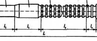
The round broach (Fig. 21) consists of the following elements. Locking part 1 (shank) serves to secure the broach in the chuck of the machine's traction device; neck 2 – connecting surface. The guide cone 3 and the front guide part 4 serve to center the workpiece at the beginning of cutting. The cutting part 5 consists of cutting teeth, the height or width of which increases by the height of the layer being cut, and serves to cut off the main portion of the allowance. To facilitate the formation of chips on the cutting teeth, chip-breaking grooves are made in a checkerboard pattern.
The calibrating part 6 is designed to give the treated surface the final shape, the required accuracy and roughness. It consists of calibrating teeth, the shape and dimensions of which correspond to the shape and dimensions of the machined surface. The rear guide part 7 is necessary to support the broach as it exits the machined hole. Rough and finishing teeth of broaches have different geometries.
The rough teeth (Fig. 21, a, section A–A) are sharpened. The clearance angle for internal broaches is 3°, for external broaches – 3–8º. The rake angle is selected depending on the properties of the material being processed within 10–20°. The pitch between the teeth is selected from the requirement that at least three teeth operate simultaneously. Lift per tooth – 0.06–0.3 mm/tooth.
A
b c
Rice. 21. Broaches : a, b – round; 1 – locking part; 2 – neck; 3 – guide cone; 4, 7 – front and rear guide parts, respectively; 5 – cutting part (cutting teeth); 6 – calibrating part (calibrating or finishing teeth); f – ribbon; Sz – rise per tooth; t – pitch between teeth; α, γ – main rear and front angles, respectively; c – broach for making an internal keyway
Finishing teeth (Fig. 21, a, section B–B) are made with a strip equal to 0.02–0.3 mm. The rake angle is selected depending on the properties of the material being processed within the range of 0–15°. A zero rake angle is usually assigned for profile broaches, which makes it possible not to lose the geometric accuracy of the teeth during regrinding. The pitch between the teeth t is selected from the requirement that only one tooth participate in the work. Lift per tooth – 0.015–0.03 mm/tooth.
Processing on broaching machines. Pulling and pulling. Broaching machines
CHAPTER
VI
PROCESSING
ON broaching machines
§ 29. broaching
AND
BROADS
Elements of the cutting mode
and
the cut layer when pulling.
Broaching has a wide range of applications, mainly in mass and large-scale production. Particularly effective is broaching parts with complex and shaped surface profiles. In Fig. 169 shows typical shapes of holes and external surfaces processed on broaching machines (shown with bold contours and lines). In mechanical engineering, broaching is used to process such standard parts elements as spline grooves, keyways, squares and flats for wrenches, rectangular and square holes. The sizes of holes and external surfaces of parts processed on broaching machines have a wide range. Broaches for processing holes can have a diameter of less than 3 mm and up to 300 mm. External broaching machines most often produce parts with a machined surface area of 100-200 cm2.
Rice. 169.
Types of drawn surfaces
Non-ferrous metals (aluminium, copper, magnesium), heat-resistant steels, titanium alloys, hardened steel with HRC 40-42, as well as plastic parts are processed by broaching. In single production conditions, broaching is used to process parts elements that are impossible or difficult to produce using other machining methods, for example, complex shaped internal surfaces of considerable length.
A feature of broaching is the absence of feed movement, since the latter is inherent in the design of the tool itself: the diameter of each subsequent tooth of the tool is greater than the diameter of the previous one by a certain amount, called feed per tooth.
Machining holes of various configurations is called internal broaching, which can be free and coordinated. Coordinate broaching ensures the exact location of holes, grooves, recesses, etc. relative to other surfaces. When drawing freely, the tool (Fig. 170, a) is guided by the pre-formed hole itself, and usually the drawn hole is used as a base for subsequent processing of the surface of the part.
Processing of planes (Fig. 170.6) and shaped open profiles refers to external broaching.
The operation of the broaches is greatly influenced by the selected scheme for cutting the allowance. The profile cutting pattern (Fig. 171, a) is provided by teeth similar to the profile being processed. The total processing allowance is cut off in layers of thickness. Generator circuit for cutting (Fig. 171, c
) is provided by teeth with a profile that only partially coincides with the profile being processed. Because of this, the latter is formed sequentially by all cutting teeth. The group (progressive) cutting pattern (Fig. 171.6) is provided by broaches with teeth, combined into groups of two, three or more. Each group of teeth cuts a layer of metal in its own zone, along part of the perimeter of the surface being processed. This allows you to work with thicker chips, especially when removing the first layers of metal.
The depth of cut when pulling is equal to the width of the cut (see Fig. 170, b), which is formed by the main cutting edge of the tooth. The thickness of the cut is numerically equal to the rise per tooth. The cutting speed when broaching is the speed of relative movement of the broach and the workpiece in the main working movement. It is limited by the conditions for obtaining the required roughness of the treated surface and is usually 1 - 15 m/min (0.015-0.40 m/s).
Rice. 170. Schemes of operation of internal (a) and external (b) broaches:
1 - broach; 2 - workpiece being processed; 3 — support washer; 4 - clamping chuck
Rice. 171. Cutting
allowance:
a - profile; b - group (progressive); V
— generator; I - broach; II - detail; 1 – metal cut with one tooth (or group of teeth); 2 - metal cut by another tooth (group of teeth)
Practice has established that with a profile pattern for cutting the allowance, the rise per tooth = 0.015 - 0.08 mm/tooth, and with a group pattern = 0.15 - 0.35 mm/tooth and the cutting part of the broach is approximately 30% shorter.
Parts, elements
and
geometry of broach teeth.
All types of broaches consist of fastening, connecting and working parts. The front shank of the broach is designed to secure it in the traction chuck of the broaching machine (Fig. 172). The length of the shank is determined by the design of the pull chuck. The neck is a transitional element of the broach. The length of the neck is calculated from the condition of placing the workpiece between the faceplate of the broaching machine and the first cutting tooth of the broach (see Fig. 170, a). The transition cone is used to ensure smooth entry of the broach into the hole being processed. Its length (Fig. 172) is usually 20 mm.
Rice. 172. Cylindrical broach with a profile cut-off scheme
The front guide of the tool is used to center it on the pre-machined hole. The diameter of guide D3 is equal to the smallest diameter of the pre-machined hole, and the length is usually taken to be no less than the length of the hole being machined. The rear guide is necessary for the correct exit of the last broach teeth from the hole being machined. Its length is taken to be equal to half the length of the hole being drawn.
A rear shank is necessary when the broach is long enough to keep it from sagging. Its length is determined taking into account the design of the machine and the part.
The working part of the broach consists of cutting and calibrating teeth. Sometimes broaches with smoothing teeth are used. The cutting teeth cut off the entire broaching allowance. Their number with a profile cutting scheme
To protect against overload, the first tooth is made without lifting.
The number of calibrating teeth is assigned from 3 to 8. A larger number is taken when the accuracy of the machined surface is 6-7th grade.
Features of the broaching process
Each broach tooth acts as a planing cutter. The low height of the teeth and the high rigidity of the broach in the diametrical plane make it possible to assign fairly high cutting conditions. In one working stroke, the entire profile of the machined surface is generated, so broaching is a highly productive process, but it has features that must be taken into account when choosing a broach and processing scheme.
When cutting, the chips removed by each tooth must be placed in the cavity between the teeth. If the volume of the cutting chips, taking into account its shrinkage, is greater than the volume of the cavity between the teeth, the broach will jam and the tool will break.
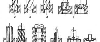
Rice. 22. Schemes for drawing holes : a – on a spherical support; b – multifaceted; c – straight spline; d – screw spline; d – keyways; 1 – spherical support; 2 – broach; 3 – workpiece; 4 – guide sleeve
Broaching with a straight cutting movement is an intermittent process. Reciprocating motion of the main motion actuator is required. Forward movement is working movement, reverse movement is idle movement. The inertia of the masses of the main movement actuator does not allow operation at high cutting speeds; usually 8–15 m/min are taken.
Broaches, or piercing, are used to process cylindrical holes after drilling, boring, countersinking, as well as holes obtained at the stage of procurement operations. When processing a workpiece with a cylindrical broach 2 (Fig. 22, a), the workpiece 3 is installed on a spherical support 1 or on a flat support.
When installed on a spherical support, the workpiece self-aligns along the broaching axis, but the end may not be perpendicular to the hole axis, so this installation is used if the end of the workpiece is processed after broaching. When installed on a flat support, the end is perpendicular to the axis of the hole, but the broach may break due to the difference in allowances in the diametrical plane of the broach.
Multifaceted holes are drawn with multifaceted broaches (Fig. 22, b). A round hole is drilled in the workpiece. Depending on the size of the processing allowance, one or another scheme for cutting the allowance is used. Splined holes are produced using splined broaches. Cutting straight splines is carried out with a rectilinear main movement (Fig. 22, c); when cutting helical splines (Fig. 22, d), additional movement is given to the broach to obtain a helical cutting movement. Keyed or other grooves are pulled through with keyed broaches (Fig. 22, d). The cross-sectional profile of the tooth must match the cross-sectional profile of the groove. The workpiece is placed on a flat support; a guide sleeve 4 is used to guide broaching 2.
Lecture No. 16
Characteristics of broaching methods;
Characteristics of broaching methods
Broaching is one of the most productive types of metal cutting. The high productivity during broaching is explained by the large total length of the cutting edges, which simultaneously participate in the cutting process.
A broach is a multi-bladed cutting tool, during the operation of which several cutting blades having a large total length are simultaneously in contact with the part being pulled. In practice, broaching is a tool adjustment, in one pass of which roughing and finishing are performed. The broaching process replaces planing, milling, rough grinding, gear and thread cutting, etc.
Broaches are complex and expensive special tools made for processing certain parts. For this reason, the economic efficiency of their use is fully revealed only with mass and serial production.
Broaches are a highly specialized tool, designed and designed for processing one or more specific parts, and at the same time quite expensive. This determines the profitability of using broaches in mass and large-scale production.
At the same time, broaches are also quite widely used in small-scale production, in particular, in heavy mechanical engineering, machine tool building, in cases where the required precision in machining a part must be obtained only by broaching, for example, when processing multi-slotted holes. The length of the drawn holes L should not exceed three times the diameter of the hole D, i.e. L = 3 D or less. The diameter of the broaches for holes ranges from 3 to 300 mm.
Broaches have high productivity, despite the fact that they operate at low cutting speeds - 3 - 8 m/min. The reason for this is the large length of the cutting edges, which simultaneously participate in cutting layers of metal. So, for example, when processing by broaching a hole with a diameter of 30 mm, if five teeth are in contact with the part at the same time, the total length of the cutting edges simultaneously involved in cutting the metal layers is approximately 470 mm. If the same part is processed with a four-tooth countersink with an allowance of 1.5 mm per side, then the total length of the cutting edges simultaneously involved in cutting will be only about 7 mm. For this reason, the broaching performance will significantly exceed that of the countersink, although it operates at a cutting speed of 20–30 m/min.
The high productivity of broaches is also due to the fact that each broach combines roughing, finishing and calibrating teeth, due to which one broaching operation can replace two or three separate operations. So, for example, broaching should be used instead of the following three operations: countersinking, preliminary and final reaming, or instead of milling and subsequent grinding of the plane.
At the same time, broaching productivity increases due to the fact that during the cutting period each tooth is in contact with the surface being machined, which makes broaching different, for example, from milling and other intermittent metal cutting processes.
For this reason, broaching is currently successfully replacing other types of processing in mass and large-scale production - countersinking and reaming of drilled holes, as well as holes produced by forging and casting; milling and planing of planes and shaped surfaces; chiselling of various shaped through holes - multi-slotted, multifaceted, curved, etc.; cutting internal gears, spur bevel gears, racks, sectors, external gears, etc.
Processing of workpieces on broaching machines
Drilling produces parts with high dimensional accuracy and low surface roughness. In terms of productivity, the broaching process is 5-10 times higher than milling and 10-15 times higher than boring and drilling. At the same time, broaching machines are simple in kinematics and easy to maintain, since most often one main translational cutting movement is built into the kinematic diagram of the machine, and the feed movement is inherent in the design of the broaching tool itself.
Surface processing by broaching is carried out both on conventional horizontal and vertical broaching machines, and on specialized equipment.
Broaching of internal and external surfaces is widely used in large-scale and mass production plants due to its high productivity and processing accuracy. Broaching, as a rule, eliminates the possibility of defects in size and cleanliness of the processed surfaces.
Broaching is used for processing symmetrical and asymmetrical through holes of various shapes, through grooves and half-open holes, external surfaces: planar, grooves, bodies of rotation.
Holes for broaching are usually pre-drilled or bored. External surfaces are treated with black broaches without pre-treatment. The previously obtained initial hole is further processed by broaching. The holes obtained by drawing are shown in Fig. 23.
Rice. 23. Various shapes of holes obtained by broaching.
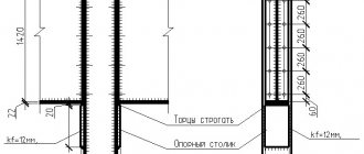
An example of keyway processing is given in Fig. 24. The guide sleeve fits into the bracket at one end, and its other end fits into the hole in the workpiece. A slot is made along the bushing through which the broach slides. Moreover, the single-key broach receives a reliable direction during operation, which ensures good quality of work and high processing accuracy.
If one end of the workpiece is not machined, then when pulling the workpiece with its unprocessed end is placed on a spherical support. Under the action of the cutting force, the workpiece rotates on a spherical support and is positioned along the broach. The treated end protects the broach teeth from the action of scale.
Rice. 24. Drilling holes: a - keyway; b - round hole: 1 - broach; 2 - workpiece; 3 - guide sleeve; 4 — thrust bracket of the machine bed; 5 — spherical lining; 6 — bushing-saddle for spherical lining 5.
The profile scheme for drawing a plane provides for preliminary processing of this plane on a planing machine. The drawing of vertical planes or the surface of a shaped profile is shown in Fig. 25.a. Here, external broach 1 processes workpiece 2, fixed in fixture 3. Figure 25b shows an example of processing a horizontal plane with an external broach. Here, several teeth are simultaneously involved in the work, the broach moves at a cutting speed V m/min, the feed per tooth Sz is simultaneously the thickness of the cut layer a mm and the cutting depth t mm, i.e. t = a = Sz mm/tooth.
Fig.25. Drilling holes: a - keyway; b - round hole: 1 - broach; 2 - workpiece; 3 - guide sleeve; 4 — thrust bracket of the machine bed; 5 — spherical lining; 6 — bushing-saddle for spherical lining 5.
In order to increase labor productivity, continuous drawing schemes are used. In this case, the workpieces move relative to a stationary broach. To ensure the rectilinear movement of the workpieces relative to the stationary broach, it is extremely important to use a closed chain with a number of devices that slide along the guides of the frame (Fig. 25.c). Securing workpieces in fixtures and releasing them after processing are carried out automatically or manually.
The relative movement of the broach and the part must be rotational. In this case, the workpieces are fixed on a rotating round table and pass under a broach attached to a stationary bracket (Fig. 25. d).
When pulling bodies of rotation with flat broaches (Fig. 25.e), the main rotational movement is imparted to the workpiece, and the broach makes a translational movement in the direction of the tangent to the workpiece.
In Fig. Figure 25.f shows the principle of processing bodies of rotation with a snail broach. This broach can be considered as a regular flat broach for external broaching, screwed onto a cylinder.
To carry out the process of external broaching with snail broaches, the workpiece receives a fast main rotational movement with a cutting speed of V m/min, and the broach receives a slow rotational feed motion Sк. At the same time, the radial feed Sz is carried out due to the excess of one tooth over the other by the amount:
Sz = R2 - R1 mm.
The working diagram of flat broaching according to the profile scheme is shown in Fig. 26. a. The broaching teeth are made with an angle of ω = 10 - 20°, which facilitates the broaching process. The cutting teeth are equipped with grooves that are staggered and serve to crush the chips into pieces. The blanks obtained after stamping and forging are processed using broaches using a progressive cutting pattern (Fig. 26. b). Such a broach does not exceed Sz between the teeth, but it is installed somewhat obliquely to the vertical, at an angle φ. In this case, Sz = tр ּ sin φ mm, where tр is the pitch between the broach teeth.
Rice. 26. Processing with flat broaches:
a – work of flat broaching according to a profile scheme;
b – broaching work of the progressive cutting pattern.
Broaching machines
Broaching machines have a simple design and great rigidity; This is explained by the fact that the machines do not have a feed chain. The main characteristics of the broaching machine are the traction force on the rod and the stroke of the working cylinder rod.
Horizontal broaching machine (Fig. 23, a) - a machine for broaching internal surfaces. On the frame 1 there is a hydraulic cylinder 3 and a pumping station 2. At the front end of the rod 4 there is a gripper 5 with a carriage 7, which can move along the guides of the frame. The broach is installed in gripper 5 and pulled through the hole in the workpiece, resting with its end on the supporting surface of the bracket 6. Translational motion is imparted to the broach until it comes out of the hole in the workpiece. The workpiece falls into tray 8. The broach returns to its original position and the process repeats.
Rice. 23. Broaching machines : a – horizontal broaching; b – vertically extended; 1 – bed; 2 – pumping station; 3 – hydraulic cylinder; 4 – rod; 5 – capture; 6 – bracket; 7 – carriage; 8 – pallet; 9 – vertical column; 10 – table
Vertical broaching machine (Fig. 23, b) - a machine for processing external surfaces. On the frame 1 there is a vertical column 9 with a working hydraulic cylinder, a pumping station 2 and a carriage 7. At the left end of the frame there is a table 10, in the working device of which the workpiece is installed. The broach is secured in the carriage. The hydraulic cylinder moves the broach from top to bottom (working stroke).
297
Cutting mode
Cutting speed.
When broaching, the cutting speed
is
the speed of translational movement of the broach relative to the workpiece.
The cutting speed is limited by the conditions for obtaining a high-quality machined surface and is limited by the technological capabilities of broaching machines. Usually u
= 8-15 m/min.
Innings. There is no feed movement during broaching as an independent movement of the tool or workpiece. For the feed amount s z ,
determining the thickness of the cut layer by a separate broach tooth, take the rise per tooth, i.e., the difference in size in height of two adjacent broach teeth;
s z
is also the depth of cut. The feed mainly depends on the material being processed, the broach design and the rigidity of the workpiece and is 0.01-0.2 mm/tooth. The optimal cutting mode values are selected according to reference data.
Litstamp Tools and Equipment
Broaching is a processing method or process that uses a multi-blade tool to remove material. metal cutting tool - broach. There are two main types of broaching: axial (or linear) and rotary. In linear broaching, which is the most common process, the cutting broach moves linearly across the surface of the workpiece. Linear broaches are used in broaching machines. In rotary broaching, the broach is screwed into the workpiece in two movements - linear and rotational - to give the axis a helical shape. Screw broaches are used in lathes or screw-cutting machines. In both cases, processing is performed in one broaching pass, which ensures high efficiency of the process. Splined and its variant involute broach usually standardized according to GOST or DIN, which allows manufacturers to produce tools not for a specific order, but to launch planned production, and at the same time significantly reduce the delivery time to the consumer. Broaching tools are used when high precision processing is required, in the manufacture of particularly complex shapes that cannot be processed by other methods. As a rule, the processed surfaces have a complex geometric shape: circle, oval, splines, involute, grooves and flat surfaces. The blanks are small and medium-sized castings, forgings, stampings and finished machine parts. Although broaches are an expensive professional tool, in comparison with other machining technologies, broaching has several advantages: 1) several teeth are involved in the work, which provides an increased value of the minute feed during the cutting process. Low speed of working movement from 2 to 15 m/min (on gray cast iron, broaches with carbide teeth operate at speeds of up to 50 m/min). The amount of allowance removed at the same time is higher than, for example, even with cutters, which determines the high productivity of the broaching process; 2) processing accuracy can reach 6th grade; 3) roughness of the processed surfaces - Ra1.25 and in some cases - Ra0.16 microns; 4) good durability of broaches; 5) the ability to eliminate defects; 6) low requirements for workers’ qualifications; 7) low operating costs of the tool.Due to the high cost of the tool and the complexity of its production, the area of use of broaches is determined - large-scale and mass production. The use of broaches in your production allows you to increase its economic effect even in small-scale and individual production, if the sizes and shapes of the processed surfaces are GOST, as well as in cases where there are no other processing options besides broaching. Broaches are made similar to a saw, the height of the teeth of which rises along the length of the tool. In addition, broaches consist of three different sections: - for roughing; - for finishing; and, finally, for finishing the product. The profile of the processed surface mirrors the profile of the broaching tool. Lift per tooth (also known as pitch or feed per tooth), determines the amount of material removed by each broach tooth. During processing, it is possible to move the broach in relation to the workpiece, and vice versa: the workpiece in relation to the broach. Thanks to its inherent capabilities, the broaching process does not require complex specialized equipment and highly qualified labor. The sequence of cutting edges following one after another ensures the formation of the required profile of the product.
Broaching technology The broaching process is determined by the type of broaching tool used. The process of flat broaching is very simple - the workpiece is installed on the table of the broaching machine, the flat broach or the workpiece is moved relative to each other. Internal drawing is a more complex process: the workpiece is installed in a jig or adapter. The technological process begins with fixing the workpiece in a special chuck, which is mounted in a broaching machine. The broaching machine has a chuck for clamping the broach shank which is part of the machine. The broach shank is passed through the prepared hole in the part. Then it is clamped in the chuck. A hydraulic cylinder pulls the broach through the part. The workpiece is removed from the machine and the broach returns to its original position. The broach usually moves linearly along the axis of the part, but for the manufacture of some parts the broach is given additional rotational movement also along the axis of the sleeve being pulled. Cutting fluids are required during machining for several reasons: 1. cooling of the workpiece and tool—broach—is required; 2. for lubrication of cutting teeth; 3. cleaning chips from the teeth of the cutting tool.
Oil-based cutting fluids are the most common in metalworking, but water-soluble cutting fluids are also widely used for their superior cooling, chip removal, and non-flammability properties.
Applications of Broaches Broaches were originally developed for machining internal splines and keyways. However, practice has shown that broaching is very effective for processing other surfaces and shapes for high-precision parts. Since each broach is specialized for a specific profile, either the broach must be designed to suit the geometry of the product, or the parts must be designed according to the geometry of standard broaches. The use of broaches, as a rule, is due to the large volume of production of parts, since the cost of producing broaches itself can reach hundreds of thousands of rubles and unique broaches for processing turbine blade grooves can reach up to a million rubles. The surface processing speed by broaching varies from 6 to 40 m/min. This leads to a reduction in the complete processing cycle to 5-30 seconds. Most of the time is spent on the reverse stroke of broaching, preparing the workpiece and installing a new workpiece and securing the tool.
There are several limitations when broaching: 1. Length of broaching, 2. Geometry of the surface being broached, 3. When internally broaching a spline hole, a pre-hole is required, 4. Hole size when internally broaching a keyway.
Typically, the outer diameter of the hole when broaching with a slotted broach or keyed broach varies from 3 to 150 mm, but in some cases it is possible to make a broach with a diameter of 1.5 to 320 mm). The length of standard broaches is usually from 400 to 1600 mm. It is possible to produce broaches with a length of up to 2200 mm. Tolerances for this type of machining are usually ± 0.05 mm, but with high-precision finishing the tolerance can be up to ± 0.01 mm.
Metal-cutting broaches work most easily: 1. on non-hard metals: aluminum, copper, brass, bronze, 2. on non-metals: plastic and composite materials, graphite, hard rubber, wood.
Broaches are still indispensable when processing involute and spline holes, when processing alloy and carbon steels. Durability directly depends on the hardness of the tool and the hardness of the workpiece. The optimal hardness of a part for high-quality performance of a broaching operation is from 16 to 24 HRC; a hardness of a product greater than 35 HRC will negatively affect the tool life. Pulling hard and viscous materials such as stainless and heat-resistant steel, titanium is more difficult, but also possible. This is achieved by changing the front and rear angles of the teeth, as well as the feed and pitch of the teeth.
The production of broaches from monolithic material, for example P18, P6M5, is the most common manufacturing method. For metal-cutting tools operating in harsh conditions and subject to rapid wear, in particular broaches working on hard materials, a different production technology is used. Such a tool is made prefabricated. Those. external cutting elements are put on the body, made in the form of a precise “rod,” which are manufactured in serial batches and therefore cost less than monolithic tools. Monolithic broaches are more expensive, but pay for themselves over time, since they are more resource-resistant and do not require as frequent replacement of replaceable cutting elements during the production process. Prefabricated broaches are usually used in mass production. They are a tool assembled from different elements: a body, cutting blades and fasteners. The prefabricated design is used because it is cheaper to manufacture and allows you to quickly change cutting elements when changing a batch of parts. The most common use is for keyed broaches to obtain a groove in parts such as bushings. To install it in the machine, or rather to ensure that it does not sag, a special device is used - an adapter. Splined broaches are manufactured mainly for the automotive industry. The auto industry and machine tool industry use them in the production of spline bushings that work in conjunction with the spline shaft. The production of screw broaches is more difficult than simple spline broaches, because they are manufactured on machines with at least 3 processing axes. This tool is mainly used for the production of gears for gearboxes. An involute broach is a variant of a splined broach, but the side surfaces of the splines are made along an involute profile - a special curved line. Our company produces them according to GOST, DIN, and also according to customer drawings.
Previous articles:
- Broaching is one of the most effective operations for processing materials by cutting, which is done using a broaching cutting tool. This operation...
“>Manufacture of broaches according to GOST
- Manufacturing of broaches
- Cutting patterns when broaching
- Straight-sided splined broaches
- Involute spline
Similar articles:
- Double-sided angle cutters
- Keyed broach
- When working on a milling machine, shaped cutters with a cutting edge are used; with such cutters it is relatively easy to process parts with high accuracy...
">Shaped cutters
- By design, thread cutters are divided into disk (single-thread) and cylindrical (comb), which are like a set of disk threads...
">Thread cutters
- A reamer is a metalworking tool for creating precise hole sizes. This process is called deployment. They can be used…
">Sweeps
Next articles:
- A milling cutter is a rotating multi-toothed tool, the cutting teeth of which come into operation sequentially, one after the other. The feed is performed by moving...
">Cutters
- Broaches are used to process through holes and external surfaces of various parts, and broaches are used only for through holes. Broaching work...
"> Broaches and firmware
- Metal-cutting tools The relationship between the structural and cutting elements of tools and the basic laws of metal cutting The work of tools…
">Relationship of cutting elements
- Production and manufacture of cutting tools General definitions of structural elements of cutting tools Main features of individual types of r...
">General definitions of cutting tools
- Production and production of hob cutters The production of hob cutters requires special control over product quality, since the slightest inaccuracy in…
">Production of hobs
Next page >>