Spread the love
Here is an explanation of the G33/G32 CNC G code that you will see on almost every CNC machine. The Fanuc CNC system only implements the G32 G code for special threading, and no G33, but regardless of whether it is G33 or G32, the functionality is the same. All the functions we can do with G33 on most CNC controls, we can do with Fanuc G32 G Code. Below I'll sometimes just use G33, but this all applies to G32 as well.
Thread cutting with G-code G33/G32
G33 is used for thread cutting, but with it we can only do one thread cutting. All this means that you must do all the work of installing the threading tool yourself.
Operating sequence for G code G33/G32
Here is the sequence of operations for cutting longitudinal threads using G33.
- Move the threading tool to the starting point. (G00)
- Make thread cutting using G32.
- Move the tool back along the x axis (G01 or G00)
- Perform rapid traverse in the Z axis to the thread starting point (G00).
- Move the x-axis tapping tool a little deeper (G01)
- Make a second thread cut using G32.
- And again and again the sequence is repeated until the depth of the carving is complete.
This thread cycle allows us to have complete control over each positioning point, we tend to call it a cycle, it is actually modal because it locks the spindle from rotating at the feed rate, just like a manual lathe does. This gives us the ability to thread a screw when programming from point to point.
G32 Screw cutting mode
G00 X8.0 Z5.0;
X4.9; G32 Z-15.0 F0.8; G00 X8.0; Z5.0 X6.0; X4.8; G32 Z-15.0 F0.8; G00 X8.0; Z5.0 X6.0; X4.75; G32 Z-15.0 F0.8; Before we look at taper threading, let's look at how the G32 works with a standard threading sequence. Here is part of the program using this command.
Feel free to download the infographic on this page for reference.
Let's look at each block to see what's happening.
G00 X8.0 Z5.0; Faster transition to a safe starting position, provided that the reference point is on the front surface of the part.
X4.9; Still in fast mode with G00 active, we go down to the first cut depth, taking a depth of 0.1mm.
G32 Z-15.0 F0.8; This is where we tell the machine to lock the spindle from rotating at feed speed so that we can cut the thread in the same place every time. From now on, every time we call G32, the machine will cut the thread along the same path as the previous one. The Z distance is the end of the thread and F is the pitch. We cut M5 threads at 0.8mm pitches.
G00 X8.0; After the first pass we program the tapping points. Increasing to X8.0mm gives us some clearance when we go back to the start of the thread.
Z5.0 X6.0; If desired, we can move along multiple axes to speed up the process. Moving 5mm to the right of the front edge will allow us to engage the threads to remove any play that may be present.
4.8; We are now ready to make the next 0.1mm deep pass. We can control the depth of each pass and reduce it as we approach the final depth.
G32 Z-15.0 F0.8; G32 will lock our turret and spindle in the same place as before, so the next thread pass will go on top of the last one. We then simply repeat this going down the X until we reach the final thread depth.
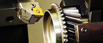
Thread cutting on a lathe: technology
Forming threads on metal workpieces in the form of bodies of rotation is one of the most popular and at the same time complex turning operations. The difficulty lies in both making basic equipment settings and preparing auxiliary tools. In order for thread cutting on a lathe to comply with the technical specifications, you must adhere to the technology for its implementation and do not forget about safety rules.
Preparing the machine
Regardless of the type of lathe and working tool, carving will be done by machining.
Through the machine settings, the operator determines the angle of the helical line of influence on the surface of the workpiece, which will have a perpendicular position relative to the axis of rotation.
Here it should be noted that the machines have different power and, accordingly, spindle speeds - in order for the cutting tool to efficiently cope with its task, it is important to initially correctly correlate the angle of influence and the speed of the engine.
An important parameter is the step between the cutting lines - it is also taken into account in the equipment settings and appropriate adjustments are made in terms of the position of the tool relative to the workpiece.
Since thread cutting on a screw-cutting lathe is usually carried out in several approaches, it is advisable to save the primary parameters until the operation is completed.
Even if the step along the threading line is maintained, there remains a risk of violating the positions of the beginning and end of the deformation sections, which may not coincide with each other. It is important to keep these nuances in mind before starting work.
Types of thread
Turners distinguish between even and odd threads. In the first case, we are talking about cuts, which ultimately form an even number of cutting lines in steps. Accordingly, odd cutting leaves odd threads. From the point of view of the operation, even cutting threads on a lathe will have its advantages.
For example, after each approach, the operator can launch a sliding nut in the support and quickly return it back with the cutter manually, without stopping the operation of the equipment.
Then, with each new pass of the sliding nut, the tool will automatically be directed to the original cavity, which ensures a certain accuracy of the operation.
In turn, odd cutting requires, after each pass, the support to return to its original position along with the cutter, which cannot be done without starting the reverse stroke.
Multi-pass and vortex cutting can be placed into separate categories. So, in the first case, cutting multi-start threads on a lathe will require precise angular separation of the workpiece during transitions from one groove to another. The initial calculation of the pitch and cutting line parameters is important here. As for the whirlwind thread, it requires additional installation of a rotating cutting head on the support carriage. Several individual cutters can be fixed on it, each of which will cover its own area of work.
Inch and metric cutting
Inch cuts are used for metal pipes. Typically, such threads are obtained from fittings, which are subsequently used to assemble a metal or plastic pipeline. The standards for creating such cutting are determined by GOST 6357-81. Based on the technical document, we can conclude that the main parameters of inch cutting are pitch and diameter. Moreover, the second characteristic is estimated as the distance between the extreme points of the thread ridges.
Typical cutting of inch threads on a lathe is carried out by cutters and taps with modifications of the technology as applied to internal processing. Metric cutting is performed taking into account the same parameters, but the shape of the thread flange profile is added to them. In the case of inch cuts, it is most often sharp - in the shape of a triangle. In addition, as the name suggests, classic pipe cutting is calculated in inches, while metric pipe cutting is calculated in millimeters.
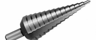
Forming threads with cutters
A cutter is a tool that directly performs cutting. It is made of carbide steel and before work receives a special sharpening in a shape that meets the requirements of the task. It can be used for threading bolts, nuts, studs and other workpieces. The cutter is installed in a machine chuck or multiple head. The work process is divided into several passes - upon completion of each of them, the tool is moved to the side.
Correction of thread formation parameters in this case is carried out by adjusting the caliper, which sets the required depth. At the same time, there are standardized settings. In particular, cutting threads on a lathe with a cutter in increments of up to 0.2 cm will imply that the feed in the transverse movement of the caliper screw will average 0.1 mm per pass.
Simultaneous work with two cutters is also allowed. But here it is necessary to take into account a nuance that can affect the quality of the thread line - the chips released by the leading cutter will cling to the waste of the second tool, which will have, although insignificant, still an impact on the parameters of the edge being formed.
Application of dies
Dies are purposefully used to work with the same hardware in the form of bolts and studs, but only when creating external threads. The area that is planned for slicing is pre-processed and cleaned.
Tapered thread
Tapered thread
G00 X7.5 Z3.5; G32 Z-73.5 X62.5 F1.0; G00 X70.0; Z3.5; X7.4; G32 Z-73.5 X62.4 F1.0; G00 X70.0; Z3.5; X7.3; G32 Z-73.5 X62.3 F1.0;
Using G32 to create threads on a cone is similar to cutting threads on a cylinder. The differences are that we have to calculate the start and end positions and set the size.
G00 X7.5 Z3.5; When we calculate our starting position, we must take into account the angle of the cone. This is where our trigonometry lessons come in handy.
G32 Z-73.5 X62.5 F1.0; When we get to the G32 block, it will be exactly the same, but we will also give an X size for the ending position of our thread. I went past the end point by 3.5mm and calculated the X position to maintain the correct taper angle to ensure exit when cutting.
Thread cutting on a lathe: including with a cutter (photo, video)
Cutting a thread with a cutter on a lathe is not the most technologically complex process, but it requires increased attention, certain skills and theoretical knowledge. It is the latter that we will tell you about, which will allow you to get as close as possible to the desired quality of processing workpieces by cutting threads with cutters.
articles
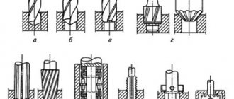
- 1 Incisors
- 2 Cutting technique 2.1 Rules for obtaining threads
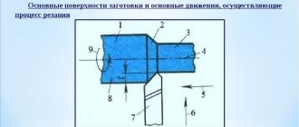
Scheme of cutting threads on a lathe with a cutter
To obtain carvings, craftsmen use different cutters:
- Pipe cutting tools;
- Threading heads;
- Taps;
- Dies.
Due to the design of the lathe, cutting threads on a lathe allows you to obtain internal and external variations in its execution.
In this case, a device that allows you to process wood by cutting threads is divided into three large categories:
- Prismatic group. This cutter can be used to process the outer sides of workpieces. At the same time, the device of the prismatic group allows you to work with large-sized workpieces. The tool is held in the machine holder by a special device called a dovetail. Thread-cutting elements of the prismatic group are subject to multiple regrinding, which makes them stand out compared to rod tools.
- Core group. The simplest device for cutting. The rod can have any cross-sectional shape; it has a working head. Depending on the shape of the head, the profile is determined. A rod jig is a shaped category of woodworking tools. The most popular of them has soldered carbide edges to cut off excess wood. They have a long service life and require sharpening less often than others.
- Round group. The heads of such devices allow you to cut internal and external threads. With such a cutter you can perform a wide range of operations, which is why they compare favorably with the prismatic group. An important feature is the ability to resharpen the tool multiple times without losing its original characteristics.
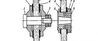
Slicing technique
Drawing of a thread cutting diagram on a lathe with a cutter
- The operator, controlling the cutter, moves it evenly along the workpiece;
- The working head itself makes a helical line with its top;
- Depending on the inclination of the line to the axis, which is perpendicular to the movement of the working tool, the angle of increase in the helical lines is determined;
- This angle depends on the characteristics of the tool feed and the rotation speed of the workpiece on the lathe;
- When the cutting device is deepened into the workpiece, it is covered inside with helical grooves;
- Using threads, you can provide high-quality fasteners, seal parts, or move elements in the required directions with a given pitch;
- Based on the configuration of the blank, the fastening receives the corresponding name - conical or cylindrical;
- The profile, which simultaneously projects across the diameter of the projection on the surface of the thread, is selected based on the purpose;
- The most commonly used profiles are acute-angled, trapezoidal and rectangular;
- Profiles are cut using a single-pass or multi-pass method;
- Multi-start ones are created from several grooves, which are located at the same distance relative to each other;
- Single-start ones are created by one groove;
- Thread characteristics are determined by pitch and stroke. This is the distance available between identical components of a threaded thread;
- To determine the distance, you need to step by the number of passes.
Rules for obtaining threads
Threading operations require that the master uses conical pipe cutting, cylindrical pipe cutting, inch, and thrust types of thread.
In order for the execution of a pipe cutting structure to proceed correctly and without errors, it is necessary to rely on certain rules when working with a die, head, tap, etc.
- First, the machine itself is configured. Threading and pipe cutting operations cannot be performed efficiently in the absence of equipment that has the appropriate characteristics and capabilities. Setting up involves adapting the device to a specific type of thread, thread-cutting and pipe-cutting heads, taps, and dies used. The setup is carried out according to the instructions for the machine and working tools. It would be a good idea to reinforce your pipe cutting skills with video lessons.
- Next, based on important rules and recommendations, work is done to create a thread with the required parameters.
- The cleanliness of the resulting thread depends on the correct placement of the working tool and its movement relative to the workpiece. To achieve the desired result, it uses a template installed parallel to the center of the turning device on the workpiece. The projection of the cutter and the template are superimposed on one another and the clearance is checked. The cutting tool must be positioned strictly on the center line of the lathe.
- To cut internal threads, use a curved working tool. If you take a mandrel, you can also use a straight tool. External cutting is carried out mainly with bent, but sometimes even, cutters. Cutters are selected based on the type of material being processed and the thread performance requirements.
- The location of the working edges of the cutters depends on the profile to be made. Triangular ones provide for the production of cutting at an apex of 55 or 60 degrees for inch and metric threads, respectively.
- The selection of the rake angle of the cutter is made based on the workpiece material. It can range from 0 to 25 degrees. In this case, a smaller angle is chosen for harder and more brittle materials.
- The lateral angles of the tool at the rear must have such parameters that when cutting, the lateral elements do not touch the surface of the thread. In most cases, the left and right sides are the same. So, if the thread angle is more than 5 degrees, the side angles will be 6-8 degrees, or 3-5 degrees if the thread angle is less than 4 degrees.
- Internal grooving is done after boring or drilling a hole. During processing, the metal is subject to deformation, which is why the diameter of the hole should be chosen slightly larger than the internal diameter. For a brittle metal, add 0.02 to the value, and for a tough metal, up to 0.4.
- Sometimes the pipe threading machine requires you to complete the cutting with grooves. The internal diameters are made 0.3 millimeters smaller compared to the same thread parameter.
- When using a pipe cutting unit in order to obtain high-quality cutting at the end, make a ledge of 3 mm (no more), without changing the diameter. This protrusion will mark the finishing pass of the cutting tool. When the job is complete, the ledge can be removed.
- Roughing using a cutting head is carried out at a speed of no higher than 30 m/min. Finishing allows the head to rotate at speeds of up to 55 m/min.
- Working with cast iron involves passing the cutting threading head at a speed of up to 25 m/min. For carbide materials this figure is up to 150 m/min.
- If the thread pitch is less than 2 mm, the work is performed at higher speeds, but decreases with a pitch of 6 mm.
- The thread is cut on a lathe using several approaches. Upon completion of each approach, the cutting tool returns to its starting position.
Example of taper thread cutting
Example of taper thread cutting with G33
N10 G50 S800 T0100 N20 G97 S800 M03 N30 G00 X90.0 Z5.0 N40 X22.026 N50 G32 X49.562 Z-71.5 F3.0 N60 G00 X90.0 N70 Z5.0 N80 X21.052 N90 G32 X48.588 Z -71.5 N100 G00 X90.0 N110 Z5.0 N120 X150.0 Z150.0 N130 M30
There are only two taper thread passes in this CNC programming example, but you can repeat the thread passes as many times as you need.