Litstamp Tools and Equipment
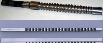
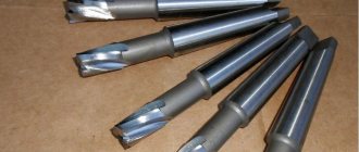
A splined broach belongs to a metal-cutting tool and is used for machining splined holes. These are, in fact, several blades secured one after another in such a way that during broaching the entire required volume of chips is removed - from roughing to finishing and calibration. In the manufacture of broaches, high-speed or medium-alloy tool steels are used, since this tool is subjected to great physical stress.Types of broaches
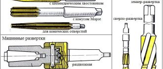
Depending on the number of reinforced cutters, broaches are six-, eight-, ten-spline, as well as involute and sharp-spline.
Six-spline broaches, depending on their type (centering along the outer or inner diameter), are manufactured according to GOST standards: GOST 24818-81, GOST 24819-81, GOST 25969-83, GOST 25970-83.
Eight-spline broaches, depending on their type (centering along the outer or inner diameter, single-pass, double-pass) are manufactured in accordance with GOST 24820-81, GOST 24821-81, GOST 25971-83, GOST 25972-83.
Ten-face broaches, depending on their type (centering along the outer or inner diameter, single-pass, double-pass, three-pass, four-pass) are manufactured according to GOST 24822-81, GOST 24823-81, GOST 25973-83, GOST 25974-83, GOST 28044 -89, GOST 28045-89, GOST 28046-89, GOST 28047-89.
Involute broaches, depending on their diameter and module size, are manufactured according to the following GOST standards: GOST 25157-82, GOST 25158-82, GOST 25159-82, GOST 25160-82, GOST 25161-82, GOST 28048-89, GOST 28049-89, GOST 28050-89, GOST 28051-89, GOST 50035-92, GOST 50036-92, GOST 50037-92, GOST 50038-92
Sharp broaches are manufactured according to GOST: GOST 28442-90
According to the shape of the spline, teeth with a herringbone, angular or straight profile are distinguished.
According to the type of manufacture, broaches are divided into solid and prefabricated.
Depending on the type of broaching, there are internal and external broaches.
According to the cutting pattern when broaching, the broach can have a conventional (profile), step (generator) and group (progressive) cutting pattern.
Splined broaches are used when processing external and internal metal surfaces - where high precision is required. Occasionally it can be used for finishing non-metallic products. Main Applications
Splined broach is used:
- in the production of rifled firearms,
— when processing external profiles of complex configurations,
- in the manufacture of aircraft engine turbines,
- when cutting keyways and splines,
— when calibrating polygonal, cylindrical or shaped holes.
At the Litstamp tool production you can purchase ready-made broaches or order the production of exclusive tools for complex work. Our designers will develop all the necessary documentation, and the masters of the tool shop will produce high-quality cutting tools in the shortest possible time.
Previous articles:
- Broaching tool
- Broaches GOST
- Straight-sided splined broaches
Similar articles:
- Shaped cutter GOST 9305
- Knurling rollers GOST 12482 - 3291
- Thread rolling rollers GOST 9539-72
- Chopping knives
- Prefabricated broaches
Next articles:
- Threaded comb cutters
- Cylindrical cutters
- Double-sided angle cutters
- Keyed broach
- When working on a milling machine, shaped cutters with a cutting edge are used; with such cutters it is relatively easy to process parts with high accuracy...
">Shaped cutters
Next page >>
HOLE MACHINING BROATS
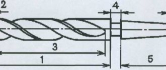
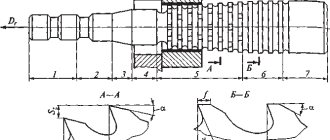
Structural elements of broaches. Broaches consist of the following main parts: shank, neck, front and rear guides, cutting and calibrating parts, rear shank ( Fig. 37 ).
| l1 |
| l2 |
| l3 |
| lp |
| lk |
| l4 |
| l5 |
Rice. 37. Structural elements of the broach for processing holes: 1 - shank; 2 - neck; 3 — front guide; 4 - cutting part; 5 - calibrating part; 6 — rear guide; 7 - rear shank
Shank
serves to connect the broach to the machine chuck. The main types and sizes of shanks are standardized (GOST 4044-70). In this case, the diameter of the shank should be 1...2 mm less than the diameter of the hole for broaching.
Neck
the transition cone
following it play an auxiliary role. Their length should provide the possibility of attaching the broach to the chuck before starting broaching. The transition cone ensures free entry of the front guide into the drawn hole. The diameter of the neck is made smaller than the diameter of the shank by 0.3 ... 1.0 mm.
Front guide
serves to center the axis of the workpiece relative to the axis of the broach before broaching, in order to prevent distortion of the workpiece, which can lead to breakage of the broach or damage to the treated surface.
The length of the front guide must be equal to the length Lo
of the hole being drawn, and for longer lengths - at least
0.6L0.
The shape of the front guide must correspond to the shape of the hole in the workpiece, and the tolerance for the diameter of the guide is taken according to8.
Rear guide
performs the same role as the front one, protecting the broach from distortion when its calibrating part leaves the machined hole. Its length is slightly shorter than the length of the front guide, and its diameter is made more accurately, with a tolerance of /7. The shape of the rear guide should be the same as the drawn hole.
To automatically return the broach to its original position after broaching, especially with large lengths and diameters of the broach, a rear shank is sometimes provided after the rear guide, fixed in the machine carriage chuck, and which is similar in shape to the front shank. The presence of a rear shank also protects the broach from sagging and distortion in the hole and avoids distortion of the shape and size of the machined hole.
Cutting (working) part
Broaching is used to remove allowance and form the surface of the drawn hole. It contains roughing and finishing teeth, and in the case of a group cutting pattern, also transition teeth located on a stepped-conical surface. The length of the cutting part is equal to the product of the number of teeth and their pitch, which, in turn, depends on the requirements for the accuracy of the hole being drawn, the roughness of its surface and the amount of allowance to be removed. The diameters of the teeth are calculated based on the adopted cutting pattern.
Calibration part
contains 4... 10 teeth of the same diameter, equal to the diameter of the last finishing tooth, and serves to calibrate the hole, reduce the dispersion of its sizes, and also serves as a reserve for regrinding: as the finishing teeth wear out, the calibrating teeth can be converted into finishing teeth by sharpening, thereby increasing the overall broach service life.
The calibrating teeth do not cut off the allowance, but remove the micro- roughness of the surface remaining after the passage of the finishing teeth and ensure the direction of broaching in the hole.
The design of the cutting part of the broach is determined by the adopted cutting pattern, which is understood as the accepted order of sequential cutting of the allowance.
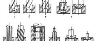
The following cutting patterns :
1 by the method of dividing the allowance by thickness and width - single and group ;
2 according to the method of forming the treated surface - profile , generator and combined .
Let's look at the first two schemes using the example of processing round holes.
Single cutting scheme (Fig. 38, a
)
is characterized by the fact that each broach tooth cuts off an allowance of a certain thickness along the entire perimeter of the hole being machined due to the fact that the diameter of each subsequent tooth is greater than the diameter of the previous one by 2аz,
where
аz
is the lift or feed per tooth
(az =
Sz).
Since ring chips are unacceptable, to divide the chips along the width on the cutting edges, it is necessary to make V-shaped chip separating grooves (Fig. 3.3, a),
which are staggered when moving from one tooth to another.
The chip separating grooves have a depth hk = 0.4... 1.0 mm and a width SK =
0.6... 1.2 mm depending on the broach diameter.
The chips removed by each tooth are obtained in the form of separate parts with a stiffening rib 2az
due to the fact that the chips are not removed in the groove area of the previous tooth.
The stiffener impairs the coagulation of chips in the grooves between the teeth, which is why it is necessary to significantly reduce the amount of feed per tooth. This leads to an undesirable increase in the drawing length. Thus, for cylindrical broaches, the approximate values of the cut thickness az
during processing are:
steels – az =
0.02...0.04 mm;
cast iron – az =
0.03… 1.0 mm;
aluminum – az=
0.02…0.05 mm;
bronze and brass – az=
0.05…0.12 mm.
With a larger cut thickness, the rigidity of the chip prevents it from curling in the cavity between the teeth. The chips rest against the bottom of the cavity, resulting in possible jamming and even breakage of the broach.
Rice. 38. Cutting patterns used when broaching:
Structural elements of broaches. Broaches consist of the following main parts: shank, neck, front and rear guides, cutting and calibrating parts, rear shank ( Fig. 37 ).
| l1 |
| l2 |
| l3 |
| lp |
| lk |
| l4 |
| l5 |
Rice. 37. Structural elements of the broach for processing holes: 1 - shank; 2 - neck; 3 — front guide; 4 - cutting part; 5 - calibrating part; 6 — rear guide; 7 - rear shank
Shank
serves to connect the broach to the machine chuck. The main types and sizes of shanks are standardized (GOST 4044-70). In this case, the diameter of the shank should be 1...2 mm less than the diameter of the hole for broaching.
Neck
the transition cone
following it play an auxiliary role. Their length should provide the possibility of attaching the broach to the chuck before starting broaching. The transition cone ensures free entry of the front guide into the drawn hole. The diameter of the neck is made smaller than the diameter of the shank by 0.3 ... 1.0 mm.
Front guide
serves to center the axis of the workpiece relative to the axis of the broach before broaching, in order to prevent distortion of the workpiece, which can lead to breakage of the broach or damage to the treated surface.
The length of the front guide must be equal to the length Lo
of the hole being drawn, and for longer lengths - at least
0.6L0.
The shape of the front guide must correspond to the shape of the hole in the workpiece, and the tolerance for the diameter of the guide is taken according to8.
Rear guide
performs the same role as the front one, protecting the broach from distortion when its calibrating part leaves the machined hole. Its length is slightly shorter than the length of the front guide, and its diameter is made more accurately, with a tolerance of /7. The shape of the rear guide should be the same as the drawn hole.
To automatically return the broach to its original position after broaching, especially with large lengths and diameters of the broach, a rear shank is sometimes provided after the rear guide, fixed in the machine carriage chuck, and which is similar in shape to the front shank. The presence of a rear shank also protects the broach from sagging and distortion in the hole and avoids distortion of the shape and size of the machined hole.
Cutting (working) part
Broaching is used to remove allowance and form the surface of the drawn hole. It contains roughing and finishing teeth, and in the case of a group cutting pattern, also transition teeth located on a stepped-conical surface. The length of the cutting part is equal to the product of the number of teeth and their pitch, which, in turn, depends on the requirements for the accuracy of the hole being drawn, the roughness of its surface and the amount of allowance to be removed. The diameters of the teeth are calculated based on the adopted cutting pattern.
Calibration part
contains 4... 10 teeth of the same diameter, equal to the diameter of the last finishing tooth, and serves to calibrate the hole, reduce the dispersion of its sizes, and also serves as a reserve for regrinding: as the finishing teeth wear out, the calibrating teeth can be converted into finishing teeth by sharpening, thereby increasing the overall broach service life.
The calibrating teeth do not cut off the allowance, but remove the micro- roughness of the surface remaining after the passage of the finishing teeth and ensure the direction of broaching in the hole.
The design of the cutting part of the broach is determined by the adopted cutting pattern, which is understood as the accepted order of sequential cutting of the allowance.
The following cutting patterns :
1 by the method of dividing the allowance by thickness and width - single and group ;
2 according to the method of forming the treated surface - profile , generator and combined .
Let's look at the first two schemes using the example of processing round holes.
Single cutting scheme (Fig. 38, a
)
is characterized by the fact that each broach tooth cuts off an allowance of a certain thickness along the entire perimeter of the hole being machined due to the fact that the diameter of each subsequent tooth is greater than the diameter of the previous one by 2аz,
where
аz
is the lift or feed per tooth
(az =
Sz).
Since ring chips are unacceptable, to divide the chips along the width on the cutting edges, it is necessary to make V-shaped chip separating grooves (Fig. 3.3, a),
which are staggered when moving from one tooth to another.
The chip separating grooves have a depth hk = 0.4... 1.0 mm and a width SK =
0.6... 1.2 mm depending on the broach diameter.
The chips removed by each tooth are obtained in the form of separate parts with a stiffening rib 2az
due to the fact that the chips are not removed in the groove area of the previous tooth.
The stiffener impairs the coagulation of chips in the grooves between the teeth, which is why it is necessary to significantly reduce the amount of feed per tooth. This leads to an undesirable increase in the drawing length. Thus, for cylindrical broaches, the approximate values of the cut thickness az
during processing are:
steels – az =
0.02...0.04 mm;
cast iron – az =
0.03… 1.0 mm;
aluminum – az=
0.02…0.05 mm;
bronze and brass – az=
0.05…0.12 mm.
With a larger cut thickness, the rigidity of the chip prevents it from curling in the cavity between the teeth. The chips rest against the bottom of the cavity, resulting in possible jamming and even breakage of the broach.
Rice. 38. Cutting patterns used when broaching: