What are they?
With the help of such supports, the rafters are attached to the supporting beam, resulting in a balanced structure. This part is also used in other cases - when it is necessary to connect several sliding elements with a fixed base.
If you are interested in what a sloping roof looks like, you can see the photo on our website.
Read more about the truss system for a pitched garage roof in a separate article.
In addition to giving the rafter structure additional strength, sliding supports have many advantages, one of which is ease of installation, which does not require special tools or skills.
The use of a sliding support reduces the cost of manual labor during the construction of the roof, since in this case there is no need to manually balance the parts of the roof structure.
Purpose of structures
Pipeline systems are the optimal way to deliver raw materials such as gas and oil to processing plants. With this method, system reliability is important. You need to take security seriously. The presence of sliding support structures increases the safety of operation in general.
The structures support the pipeline system and absorb static loads from the mass of the pipes and the technological products filling them (weight load). These loads must be distributed evenly along the entire length of the pipeline to prevent increased stress in individual sections. There is also a change in linear dimensions associated with changes in the ambient temperature and the temperature of the transported substance.
When pumping, pipeline systems may experience torques, lateral and vibration loads. Support structures are designed to absorb and redistribute these loads. According to application, the following types are distinguished:
- Fixed . Prevents pipe movement. The elements are welded to the supporting surface.
- Movable . They are fixed on the pipe and can move relative to the support platform, providing the necessary design parameters.
- Sliding supports for pipelines are one of the types of movable support structures. They provide longitudinal movement of pipes, as well as transverse movements over a given distance.
Structural elements are sliding and roller bearings, fasteners, clamps.
Functions and characteristics of sliding supports
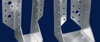
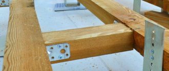
The purpose of the sliding supports is to attach them to the mauerlat during the construction of log and timber houses. These perforated elements have repeatedly proven their effectiveness: the sliding method of fastening prevents the roof structure from hanging and the walls of a wooden building from bursting.
Absolutely all buildings created from solid wood (this includes chopped and rounded logs and profiled timber) are subject to natural shrinkage. As a result of shrinkage of the rafter system of a wooden structure, the structure weakens and significant distortions are possible. Floating rafters made using sliding supports solve this problem.
The components of these fasteners are a metal bracket and an angle with a loop. Basically they have the following parameters:
- height: 90 mm;
- width: 40 mm;
- thickness: 2 mm;
- length: from 90 to 160 mm
Since the rafter system must withstand heavy loads, all fasteners used, including sliding rafters, must be made of durable and reliable materials. Low carbon steel, which is the material used for making sliding fasteners, meets these requirements
The process of installing a roof structure using these fasteners is not difficult: it only requires a screwdriver.
Scope of use of supports
The process of shrinkage of wooden houses is especially intense during the first few years of operation. Changes in the shape and size of the structure are mainly due to changes in temperature and humidity levels. In this case, the height of each individual log or beam changes, resulting in a general change in the height of the wall, which consists of changes in the parameters of each element separately. From the above, we can conclude that as the height of the wall increases, the degree of its shrinkage during operation also increases. The wall located under the ridge has the maximum height, which means its shrinkage is the greatest.
The walls that serve as support for the rafters located along the edges of the house are subject to less shrinkage. Over time, this process leads to a change in the angle of the roof. For this reason, it becomes necessary to take into account the data of geometric changes when attaching rafters and ensuring the mobility of connections.
The rafters located in the ridge are created to rotate relative to each other, securing them on both sides with the help of metal-based plates on studs.
The lower edges of the rafters present a certain difficulty, since during shrinkage they not only rotate, but also move relative to the wall. The device of a rigid and fixedly fixed fastening of the rafter leg to the wall will lead to its bulging as a result of shrinkage.
For rafters, it is necessary to ensure the possibility of a not very large, but still noticeable rotation and a certain shift along the wall without reducing the degree of strength of the fastening. In earlier times, annealed wire was used for this purpose. With its help, the top log was tied to the rafter leg. This technique ensured the mobility and reliability of the created fastening .
Sliding supports for rafters have become an effective, most convenient in terms of installation and a replacement for the described method that meets all requirements. When using it, the rafter leg is securely fastened to the beam or log of the mauerlat. If laminated timber is used in the rafter system, this method becomes the only one that simultaneously provides the necessary mobility and strength. The location of the fastening is the area along the displacement of the beam. To do this, the wood of the top beam is ground down. The result is a platform - the fixed lower part of the support is attached to it.
When performing installation, the support must be positioned in such a way that its shift reserve is the maximum possible.
As a rule, the rafters are fastened on both sides of the rafter leg, however, with a low roof and a small slope of the roof slopes, you can limit yourself to one fastening.
The rafter leg, which has intermediate supports between the mauerlat beam and the ridge, must also be secured with a sliding support.
Pipe supports: use cases
The main function of pipeline supports is to secure the communication in a certain position. They also prevent pipes from deforming under the influence of temperatures and vibrations. The fact is that vibrations often occur when transporting the working medium through the system.
It is extremely important to pay utmost attention to the installation process, since the reliability of communications depends on the supporting elements. If mistakes are made, they simply will not cope with the tasks assigned to them.
Let’s say right away that these products are used in a variety of fields and differ in type and purpose. So, installation of communications cannot be done without them:
- at enterprises;
- in housing and communal services;
- at nuclear power plants;
- at thermal power plants;
- in the gas and oil sectors.
If we are talking about a gas pipeline, then especially serious requirements are placed on the supports, including when the pipeline runs through regions that are unfavorable from a climatic point of view. It is equally important that the supporting structure protects the pipes from damage in the most vulnerable places, that is, at the fastening points.
The terminology of GOST 22130 defines supports as a structural element of the pipeline, that is, they cannot be called a transitional structure between pipes and foundations.
As we have already said, supporting elements are used when laying communications in a wide variety of industries. The necessary products are selected depending on their purpose in such a way that they allow the transmission of axial, transverse, vertical loads, torques to the soil or load-bearing structures.
Manufacturing of sliding supports
In most cases, these parts are operated at high humidity and often come into contact with water and condensate penetrating under the roof slope. When manufacturing sliding supports, it is necessary to take into account the strong impact of these and other negative environmental factors. For this reason, they are pre-coated with a layer of molten zinc, additionally alloyed with other substances to reduce susceptibility to corrosion and improve strength characteristics, thereby increasing the overall load-bearing capacity of the structure.
The sliding supports themselves are manufactured by cold stamping on the basis of a fairly strong and ductile material - low-carbon steel grade 08 PS. The percentage of carbon in it is 0.08%, which makes it possible to stamp the material with high quality. Balancing the strength characteristics of the element is carried out by deoxidation.
Production
To manufacture polyurethane foam supports for pipelines, hoists of different brands are used. The choice of material is influenced by the expected operating conditions and design documentation. Supports are required for laying cold water and heating water pipelines; they can be used when installing gas and oil pipelines.
The company produces 2 types of products:
- intended for laying PPU-PE pipes (used for underground installation, in a channelless manner);
- intended for installation of PPU-OTs pipelines (used for above-ground installation).
The products offered by the Spetsneftemash enterprise are suitable for laying PPU PE and OC pipes. They are manufactured in accordance with the requirements of GOST 30732. The cost of products depends on the size, type of metal products, type of insulation, and order volume. It is possible to order non-standard designs. Pickup or delivery to any region is possible. Email
Steel grades used:
- St3,
- St20,
- 09G2S.
Types of sliding supports
All currently used sliding supports are divided into two groups:
Open type - such structures are composed of two separate elements. The first is the guide attached to the rafter leg. This is a curved steel plate with holes at the ends. There may be two or three of them at each end - the specific number depends on the manufacturer. The stroke length of the moving element also changes. The smallest value should be 60 mm, the largest – 160 mm. The corner (the fixed part of the element) has up to 5 holes.
Closed type - this type of support is not disassembled into its component parts and represents an integral structure. Installation is carried out in assembled form. With this option, the fixed part has the shape of a corner with a special holder on the long side: a fastening bar is threaded into it.
Pipeline supports: norms and standards
At the moment, standards have been developed at the state level for two categories of such products:
- GOST 14911-82 “Parts of steel pipelines. The supports are movable. Types and main sizes." It applies to movable structures made of steel grades OPB (frameless), OPH (clamp), OPP (movable welded);
- GOST 16127-78 “Parts of steel pipelines. Pendants. Types and main sizes." It applies to pendants designated PM, PG, PMV, PGV.
If we talk about industry standards for assembly units for fastening gas pipeline pipes, then in Moscow there are 2.5 times more of them:
- OST 108.275.24 – pipelines of nuclear power plants and thermal power plants;
- OST 24.125.154 – pipelines for nuclear power plants and thermal power plants made of high-alloy and special steels;
- OST 36-94 – moving elements of technological lines;
- OST 36-104 – steel structures for systems working with media characterized by low temperatures;
- OST 36-146 – series KN, VP, TO, KhB, UP, ShP, TP, KH, KP, TX, TP for diameters 57 – 1420 mm.
There are also three subordinate TU standards relative to GOST. They are used in the production of the models we describe:
- TU 1468-012-04698606 – moving elements of process piping, used at a pressure of 10 MPa, temperatures from -70 °C to +450 °C, pipe diameters of 18–1620 mm;
- TU 1468-002-92040088 – suspension, supports and block modules for pipelines 32 MPa, DN 15–1600 mm;
- TU 1468-001-00151756 – sliding elements for diameters 100–1400 mm, temperatures from -70 °C, pressure 10 MPa.
There are also two series of assembly units of this type:
- 903-10: 4th edition - for structures mounted motionlessly, 5th edition - for movable modifications, 6th edition - for suspensions;
- 903-13: issue 6-95 – pendants, issue 7-95 – fixed elements, issue 8-95 – movable.
The album of drawings T-MM-26-05 includes options for the design of movable and dead structures of PS, ONS and OSS. In the documentation NTS 65-06 you can find working drawings and technical regulations intended for the manufacture of software and non-productive software.
Some recommendations for installing sliding systems
- Installation of sliding rafter systems is carried out on objects of the correct geometric shape. In other cases, the correct execution of the roof is quite problematic, since the systems are equipped with moving elements. Before the installation of rafters begins, a thorough check of the perimeter of the object is carried out to ensure that it meets the required standards.
- Rafter systems are created using a pre-fabricated template. Thanks to this approach, it is possible to obtain identical structures for all roofing elements.
- In rafter systems of this type, the ridge connection is also created using movable elements. Mounting parts can be studs and bolts, which represent the connecting axis, as well as movable hinges secured with self-tapping screws.
- A significant length of overlapped spans often requires the extension of boards used for the manufacture of rafter structures. In this case, the boards are connected using long bolts or special brackets. The boards are overlapped along pre-drilled mounting holes. During the drilling process, it must be taken into account that the holes must be located at a distance of at least 10 cm from the edge of the board. Drilling is carried out randomly, which helps prevent possible splitting of the board along the holes.
- The installation of each of the supports of the sliding rafters is carried out strictly parallel to the previous one and perpendicular to the location of the load-bearing log of the structure. Failure to comply with this rule may cause jamming of the moving parts of the structure and their subsequent destruction during the process of shrinkage of the building.
- “Slippers” are mounted at a 90-degree angle with respect to the rafter support using special cuts. This method ensures unimpeded movement of the structure. During the installation process, these elements must be brought to their extreme position, which will ensure the maximum possible movement of the entire truss structure during shrinkage of the building.
Important information about how the hip roof truss system is calculated.
Roof aerators: why they are needed and what types there are - read here.
Find out how to insulate a sloping roof from the article https://rooffs.ru/vidy-krysh/lomanaya/osobennosti-utepleniya-krovli.html.
Types of pipeline supports
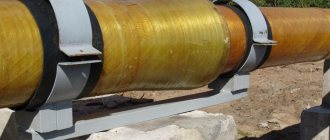
1. Hull supports.
To connect structural elements in space, a box-shaped housing is often used. It is made of sheet steel or welded from individual elements. Body supports are mounted on a beam, have stiffening ribs, and are supplemented with cushions, clamps and yokes.
When using the housing, the pipe rises by 100–200 mm, making it convenient to fasten and maintain during operation. If we compare the cost of a bent angle and a range of rolled metal products, then purchasing the former turns out to be more profitable and reduces the cost of the entire structure.
2. Frameless supports.
This is a traditional model, which is a sheet steel cradle bent in accordance with the outer shape and diameter of the pipeline. Most often this element is called a “pillow”. It can also be equipped with a round, strip or tape clamp and a support plate, which has holes for fixing.
The design is simple, its production requires a minimum amount of materials, and it itself consists of a very small number of parts. For this reason, the open-frame model is called the most affordable one used in pipeline construction. For such support elements there are markings T11, HB, OPB.
3. Tubular supports.
If we talk about the design of this element, then we have a vertically located pipe, welded to a plate with holes for installation. To increase the contact area of the support pipe with the pipeline, a saddle-shaped cut is made at its upper end with a laser or cutter, which corresponds in shape to the main pipe.
When releasing such models, they are based on the OST 36-146-88 standard. This type is suitable for pipelines with a diameter in the range of 57–630 mm and medium temperatures up to +450 °C. There are currently four versions in total: A1, B1, A2, B2. Such products are marked TR; stainless steel, structural and carbon steel are used in their production.
4. T-bar supports.
T-bar elements can have different designs and are made of two types:
- Welded. In this case, a piece of the brand is installed on a single shelf, plates are welded at the ends, and a radius cut is made in their upper part in accordance with the diameter of the pipe for better fixation of the pipeline.
- Clamps. We are talking about strip or tape clamps that are welded on top of a piece of rolled metal, and holes for fastenings must be provided in its shelf.
These types of T-bar support structures are labeled as TP and TX. Various methods of connecting pipeline elements can be selected, thus achieving complete immobility of the unit or several degrees of freedom of the connection.
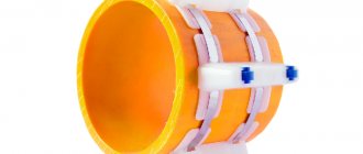
5. Clamp supports.
They occur when using both movable and fixed connection methods. Then the following types of fastening can be used:
- bar clamp;
- strip clamp;
- band clamp;
- flat clamp;
- rope clamp;
- mounting on the body;
- with frameless supporting structures;
- for welded and sliding supports for pipelines;
- the clamp is used as a guiding element.
The clamp tightly grips the pipe on all sides; gaskets made of dielectric and antifriction materials can be used with it. Also, with this fastening method, one degree of mobility of the pipeline along its axis can be achieved.
The classic model is an inverted U-shaped structure with or without stiffeners.
Clamp elements are used for pipelines with a diameter of 57–377 mm, while the yoke type is suitable for sizes 377–1420 mm. It is worth noting that assembly units can be marked differently, this is due to the fact that several standards are used in their production.
6. Welded supports.
Sliding and movable support structures are rigidly attached only to the base/stands or directly to the base and pipe. Welded support structures come in the following modifications:
- sliding guide;
- sliding motionless;
- steel;
- motionless;
- sliding;
- corner;
- on a beam with eyes.
For their production, they take rolled and bent angles, T-bars, channels, pipes or curved, welded bodies.
7. Supports for vertical pipelines.
According to OST 36-17-85, supports for technological vertical pipelines and piping of technological lines are manufactured. Most often we are talking about a strip, rod or yoke clamp, which is attached to a corner or in a bent body.
In the documentation, such structures are usually referred to as VP; usually these are fixed models. In this case, the main characteristics are considered to be material, diameter, face-to-face length, temperature and pressure of the working medium.
8. Rope supports.
A yoke is nothing more than a type of clamp, supplemented with special fasteners or studs. Yoke models are divided into types according to the design of the assembly unit and are:
- tubular;
- strip;
- case;
- stamped;
- stamped and welded.
This element is installed in this way: the pipe is laid on a cushion or cradle with holes for the studs, after which the yoke is pulled on top of the threaded connections. To make it easier to clamp the pipe, special mechanisms, claws, traverses, clamps or beams can be used.
9. Roller supports.
The design of this model stands out from the general background due to the following characteristics:
- two or more support platforms are provided;
- installation is carried out between the bearing supports;
- axial displacement of the pipeline by a specified amount is allowed;
- It is allowed to move the pipes sideways by 50 mm.
It is possible to produce one- and two-level elements, with one roller and several blocks, and the enterprises also produce clips for pipelines of energy facilities, steel and spring models. Rolling elements can significantly reduce the level of friction, and hence the wear rate of the elements of the entire structure. As a result, the service life increases, and assembly units are easier to repair.
10. Side supports.
The design of this element includes a plate and a support, which is necessarily equipped with several stiffening ribs for reinforcement. This model differs from the welded one only in its location in space, because it is mounted on a vertical surface, due to which it compensates for lateral loads, but does not perceive vertical forces.
Such elements are marked as T10 and are suitable for pipes with a diameter of 194–1,420 mm.
11. Frontal supports.
If we consider the location of the frontal models relative to the flow of the working medium and the body of the pipes, then they are installed in a transverse projection. These products are usually divided into types based on the material of manufacture and design:
- panel panels are made of reinforced concrete, often having several stiffening ribs;
- thrust ones are a pair of stops in a vertical or horizontal plane on both sides of the pipeline; they can also be four stops on all sides.
Double-supported frontal elements are installed when it comes to small axial loads, while four-supported ones are necessary for serious loads. If necessary, the entire structure can be reinforced with half rings and stiffeners.
12. Fixed supports.
This type of structure is necessary if it is necessary to exclude any mobility of communications relative to supports and foundations. Manufacturers offer the following design options designed for different operating conditions:
- "dead";
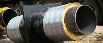
- for pipes in thermal insulation PPU;
- frontal and side thrust;
- yokes and clamps;
- hulled and unhulled;
- for vertical boxes;
- persistent reinforced;
- panel reinforced concrete;
- welded and steel.
To designate these pipeline elements, the abbreviation NOP is used. This type is suitable for installation with pipes with a diameter of 32–1,420 mm and is intended for conditions with increased operating loads.
13. Movable supports.
If it is necessary to achieve one or more degrees of mobility of the pipeline relative to the foundation or supporting structure, various movable models are used:
- clamp OPC;
- welded OPP;
- unframed OPB.
The rules for the manufacture of such supports for pipelines are established by GOST 14911-82, OST 36-94-83 and 36-146-88, in addition, the specifications of individual enterprises, drawing albums T-MM-26-05, and other documentation are taken into account.
14. Sliding supports.
This type of moving elements provides one degree of freedom in the axial direction. In this case, the following execution options exist:
- steel and welded;
- underlay and in a case for pipes in PPU thermal insulation;
- for pipelines of thermal and nuclear power plants;
- with flat clamp and bracket;
- sliding fixed and guides of several types;
- dielectric and yoke;
- clamp and frameless.
To resist rapid wear of pipes and system elements, anti-friction gaskets, rollers and blocks are used.
15. Adjustable feet.
They are chosen if precise vertical positioning of individual sections of the pipeline is necessary. Let us say right away that such structural elements necessarily have movable wedge stops. Assembly units are marked OR, and in their manufacture the standard TU 5263-003-93646692 is used. Another important element of such a supporting structure is the support. It is raised and lowered by moving the wedge stops, which are attached to the plate by bolted connections.
16. Dielectric supports.
Such elements are necessary to protect the pipeline from stray and induced currents. To do this, use a gasket made of any dielectric material, for example, paronite, which has anti-friction properties.
17. Supports for reinforcement.
OST 36-17-85 establishes standards for the production of structures for the installation of OKA pipeline fittings. From a technical point of view, these are four stiffeners that are cross-welded together and mounted on a support plate. In their upper part, the stiffeners follow the outer contour of the installed pipeline fittings.
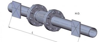
18. Unloading supports.
This design is necessary to compensate for water hammer, vibration and mechanical loads that cannot be avoided during the operation of pumping and compressor equipment. Such an element consists of a pipe and has several degrees of freedom relative to the foundation. In its production, they rely on SNiP 3.05.05-84, and GPA markings are used.
Installation
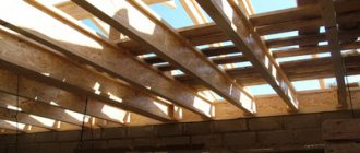
Sliding rafters are installed when the material for the gables is logs or beams, and the ridge purlin is fastened in the body of the gable. This requirement is necessary to prevent the walls from expanding when the roof slope angle changes during shrinkage.
The rafters are laid on top of the ridge girder and secured with a hinge joint. In this case, it remains possible to change the angle at which the rafter legs are connected.
The manufacture of such a connection is made on the basis of perforated plates connected by pins. The second option is to overlap the top pieces and connect them using studs with washers and nuts.
In this case, certain conditions must be met:
- The connection of the mauerlat (in this case, the upper crown of the log house) with the rafter legs is carried out using sliding supports. As a rule, their sizes correspond to the following parameters:
- 90 x 90 x 40;
- 120 x 90 x 40;
- 160 x 90 x 40;
- 270 x 90 x 40 mm
The choice of length is determined by the expected displacement of the rafter legs.
- Sliding supports are mounted using self-tapping screws with a protective coating - otherwise they can become the weakest link of the entire structure.
- During installation, the sliding support guide must be fixed parallel to the rafter leg, and the angle is installed perpendicular to the leg in the upper part. This technique ensures the possibility of sliding with the maximum possible shrinkage length.
- The rafter legs are laid on the mauerlat from above or by inserting into the body of the mauerlat. The maximum permissible insertion depth should not exceed ¾ of the diameter of the log or mauerlat beam.
- The material for making rafters are boards with a section of 200 x 50 or 200 x 150 mm. They must be treated with special bio- and fire retardants.
Distance between pipeline supports
However, it is not enough to know the types of supports for pipelines and buy all the necessary elements. For competent construction, you need to clearly understand the distance between these structures, because only in this case the system will work properly. The distance is set in accordance with the requirements specified in the relevant documentation, as well as on the basis of information about the scope of operation of the pipeline, its weight, and possible deflection during service.
The values are calculated based on data from the table “Design of Heat Networks” by A. A. Nikolaev. So, for horizontal placement, the table suggests the following calculation: with a minimum pipe diameter of 20 mm and a maximum working environment temperature of +60 ˚C, the supports should be 60 cm apart from each other. The rule works here: the larger the pipe diameter, the larger the pitch used.
The same calculation principle is used if vertical placement is planned. Let’s say the main line has a diameter of 40 mm and a temperature of +20 ˚С, then the length of one segment is 138 cm. If the network temperature reaches +70 ˚С, then the length of the segment is reduced to 113 cm.
When arranging fixed metal supports, the schematic characteristics of thermal communications are taken into account. Typically, such structures are installed near main branches, shut-off valves and in straight sections, taking into account the properties of the expansion joints installed there.
The distance between the fixed elements of the system is calculated as follows:
L = 0.9 × ∆L / (a × (t-tpo)), where
- ∆L – compensator capacity, in mm (values are taken from the table);
- a – coefficient of linear expansion of steel walls during temperature fluctuations, in mm/m˚С;
- L – length of the pipeline section for which the calculation is being made, in m;
- t – calculation of the temperature of the working environment during installation, in ˚С;
- tрo – ambient temperature;
- 0.9 – error value (equal to 10%).
To calculate the distance between the sliding fasteners, it is necessary to understand the scope of use of the entire system. The fact is that, for example, for a cold pipeline this step will be greater than for communications through which hot water flows.
CONCLUSIONS:
- The sliding support for the rafters is a very important element of the roofing structure, allowing to compensate for the distortions of the rafter system that arise during operation due to wood shrinkage.
- With the help of such supports, the rafters are attached to the supporting beam, resulting in a balanced structure.
- The sliding method of fastening prevents the roof structure from hanging and the walls of a wooden building from expanding.
- The components of these fasteners are a metal bracket and an angle with a loop.
- The production of sliding supports is carried out by cold stamping based on low-carbon steel grade 08 PS.
- Sliding supports are of open and closed types.
- “Slippers” are mounted at a 90-degree angle with respect to the rafter support using special cuts. This method ensures unimpeded movement of the structure.
- The sliding supports are secured using self-tapping screws with a protective coating.
- To ensure the possibility of sliding with the maximum possible shrinkage length, the guide line of the sliding support must be laid parallel to the rafter leg, and the angle is installed perpendicular to the leg in the upper part.
Find out how rigid and sliding connections of rafters are made from the video.
Application
Supporting metal structures are used in the construction of field, technological, and main pipelines. In particular, they are used in the construction of oil and gas pipelines, water pipelines, fuel pipelines, heating mains and other pipeline structures.
Sliding supports are installed to compensate for vertical and lateral stresses that appear when:
- heaving, subsidence or collapse of soil;
- seismic activity of the territory;
- wind and snow loads;
- water pressure when laying a route under water bodies.