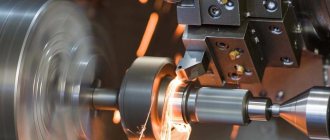
The grinding process is considered a very complex surface treatment process, which has its own specific features, which distinguish it from all other metal processing processes by cutting with tools made of metal alloys, solid carbide and with replaceable inserts that have the correct geometry.
The complexity of the grinding process and the variability of the cutting tool - the grinding wheel, in particular, create great difficulties in the practical and theoretical study of this finishing process of materials processing.
Metal grinding
What is metal grinding? This technology means its processing using abrasive material. This process is carried out using a special technique and is designed to change the texture of the surface, as well as its other characteristics. Grinding is applied to the outer and inner parts of the metal (flat or cylindrical).
Metal processing characteristics:
- grinding is the final stage of metal processing, which is carried out to create roughness;
- the technology is not suitable for radically changing the dimensions of the product;
- It is possible to obtain the required degree of roughness using modern equipment after processing the workpiece under high temperature.
In the process of metal grinding, a number of features are taken into account:
- cutting depth;
- possibility of cross feeding;
- product movement speed;
- wheel speed (depending on equipment characteristics and outer diameter).
Grinding
General information about sanding
Grinding is one of the types of metal cutting processing. In Fig. Figure 10.1 shows typical parts processed on grinding machines. Among them are simple cylindrical rollers and complex engine crankshafts, splined rollers and bed guides, rings and long pipes, worms and gears, parts formed by flat surfaces, and parts whose surfaces have a complex spatial shape. Most often, external and internal cylindrical surfaces are processed during grinding.
Rice. 10.1. Typical parts processed on grinding machines
When grinding, the processing allowance is removed with abrasive tools - grinding wheels. Grinding wheel 1 (Fig. 10.2) is a porous body consisting of a large number of abrasive grains 7, connected to each other by a special substance 5, which is called a binder. The hard materials from which the grinding wheel grains are formed are called abrasives. The grinding process consists of the fact that the grinding wheel 1, when rotating, removes, while moving the part 8, a thin layer of metal (chips) with the tops of its abrasive grains located on the cutting surface.
Rice. 10.2. Scheme of interaction between the grinding wheel and the workpiece:
1 – grinding wheel; 2 – direction of rotation of the circle; 3 – cutting surface (periphery of the circle); 4 – direction of feed of the part; 5 – ligament; 6 – it’s time; 7 – grain; 8 – part to be ground
The number of abrasive grains located on the periphery of the grinding wheel is very large; it is measured on medium-sized circles in tens and hundreds of thousands of pieces. Therefore, when grinding, chips are removed by a huge number of randomly arranged cutting grains, also of irregular shape, which leads to very strong crushing of the chips and causes high energy consumption.
The elements of the cutting mode in cylindrical external grinding are the peripheral speed of the grinding wheel, depth of cut (transverse feed), longitudinal feed and rotation speed of the part.
Peripheral speed of the grinding wheel . In practice, wheel speeds from 20 to 60 m/s are used. The peripheral speed of the circle (m/s) can be determined by the formula:
where D is the diameter of the circle in mm;
n – number of revolutions per minute (rpm).
The peripheral speed of the workpiece is usually measured in meters per minute (m/min), since it is significantly less (usually 60–100 times) than the peripheral speed of the wheel. The speed of the part can be calculated using the formula:
where d is the diameter of the part in mm;
nd – number of revolutions of the part per minute.
The speed of rotation of the part is sometimes called circular feed.
Grinding depth . The amount of transverse movement of the grinding wheel in the direction perpendicular to the machined surface during one longitudinal stroke is called the depth of cut, or transverse feed. The cutting depth is the thickness of the metal layer removed in 1 pass. During cylindrical finishing grinding it ranges from 0.005 to 0.015 mm, and during rough grinding it ranges from 0.010–0.025 mm. Sometimes the grinding depth can be greater.
Longitudinal feed . Longitudinal feed during cylindrical grinding is the path traveled by a workpiece (or wheel) in a direction parallel to the axis of rotation of the wheel in 1 minute or during 1 revolution of the workpiece being ground. Therefore, longitudinal feed can be measured in the following units: in fractions of the height (width) of the circle per 1 revolution of the part; in millimeters per 1 revolution of the part (mm/rev); in millimeters per 1 minute (mm/min). The amount of longitudinal feed during cylindrical grinding depends on the type of grinding: for rough grinding of parts made of any materials with a diameter of less than 20 mm, the feed is taken from 0.3 to 0.5 N (where H is the height of the grinding wheel); when rough grinding parts of larger diameter made of hardened steel - up to 0.7N; for parts made of unhardened steel - up to 0.75N and for parts made of cast iron - up to 0.85N. When finishing grinding, the feed is (0.2–0.3) N, regardless of the material and diameter of the workpiece.
Cooling during grinding . To remove generated heat from the cutting zone, reduce friction and remove grinding waste, abundant cooling with various coolants is used.
Cast iron and copper alloys can be ground without cooling, and the machines must be equipped with vacuum cleaners that remove abrasive dust. The coolant, by washing away abrasive metal dust, helps improve the quality of the ground surface.
In mechanical engineering, the following types of grinding are most often used: external round, internal round, flat and centerless.
Cylindrical external grinding
In external cylindrical grinding, the workpiece is mounted in centers or secured in a chuck. There are grinding with longitudinal feed, deep grinding and plunge grinding.
To carry out the grinding process, it is necessary that the workpiece and the abrasive tool have appropriate relative movements.
When external cylindrical grinding with longitudinal feed requires the following movements (Fig. 10.3a): rotation of the grinding wheel is the main cutting movement; rotation of the part around its axis - circular feed of the part; rectilinear reciprocating movement of the part (or grinding wheel) along its axis - longitudinal feed; transverse movement of the grinding wheel onto the part (or parts per wheel) - transverse feed, or feed to the grinding depth. When grinding with longitudinal feed, transverse feed is carried out periodically, at the end of each double or single stroke of the table. When deep grinding, the allowance is removed in one pass, and the longitudinal feed is chosen to be very small. When performing circular external plunge grinding (Fig. 10.3b), the height of the grinding wheel used is taken equal to or slightly greater than the length of the part. Therefore, there is no need for longitudinal feed here. Transverse feed, unlike the first method, is carried out continuously throughout the entire grinding process. Thus, to perform external plunge grinding, the following movements are necessary: rotation of the grinding wheel, rotation of the part around its axis (or its circular feed) and continuous transverse feed of the grinding wheel.
Rice. 10.3. Schemes of the main types of grinding:
a – round external with longitudinal feed; b – round external plunge; c – round internal with longitudinal feed; g – external centerless; d – internal centerless; e – flat periphery of the circle; g – flat end of the circle
Cylindrical internal grinding
This type of grinding includes grinding with longitudinal feed and plunge grinding.
For circular internal grinding with longitudinal feed (Fig. 10.3c), the same movements are required as for circular external grinding with longitudinal feed: rotation of the grinding wheel, circular feed of the part, longitudinal feed of the part or wheel, transverse feed of the wheel.
Centerless grinding
With centerless grinding, the cutting process is carried out with a grinding wheel in the same way as on conventional center grinding machines. The peculiarity of this process is determined by the specifics of fastening and feeding the part. With centerless external grinding (Fig. 10.3 d), the part to be ground is placed on a support knife between the working circles (on the left) and the feed or driving circle (on the right). To carry out the centerless grinding process, the following movements are required: rotation of the grinding and feed wheels, circular and longitudinal feed of the part. The rotation of the feed wheel imparts rotation and longitudinal feed to the grinded part. To obtain longitudinal feed of the part, the axis of the driving circle is set at a small angle α to the axis of the working circle.
Cylindrical internal centerless grinding (Fig. 10.3e) is similar to external grinding and is carried out without securing the part being ground. During the grinding process, the workpiece is supported by 3 support rollers.
Pages:
- |
- |
- |
- |
- |
- |
- |
- |
- |
- |
- |
- |
- |
- |
- |
- |
- |
- |
- |
- |
- |
- |
- |
- |
- |
- |
- |
- |
- |
- |
- |
- |
- |
- |
- |
- |
- |
- |
- |
- |
- |
- |
- |
- |
- |
- |
- |
- |
- |
- |
- |
- |
- |
- |
- |
- |
- |
- |
- |
- |
- |
- |
- |
- |
- |
- |
- |
- |
- |
- |
- |
- |
- |
- |
- |
- |
- |
- |
- |
- |
- |
- |
- |
- |
- |
- |
- |
- |
- |
- |
- |
Main types of grinding
Metal grinding is done using various methods. Technologies differ in the method of rotation (of a wheel or a workpiece), the speed of movement, as well as the side on which the grinder works (end, plane) and other factors. Main types of grinding:
- round;
- grinding of internal surfaces;
- gear grinding;
- centerless;
- flat.
Grinding methods are also classified according to the type of material used in the processing. To transfer the process to automatic mode, special machines or a built-in CNC unit are used, which reduces labor costs and ensures high quality products.
Cylindrical external grinding
Cylindrical grinding is the most popular method. It is not only external, but also internal. The circular method is carried out due to the synchronous rotation of the circle and the metal part. External grinding provides a cutting effect, and internal grinding provides uniform work.
Among the features of cylindrical grinding are:
- the abrasive wheel is a consumable material, it rotates around its own axis;
- the metal part rotates synchronously with the circle (this increases the efficiency of the process);
- Both longitudinal and transverse feeds are carried out (due to them, the depth of infeed changes and processing is ensured along the entire length).
This technology is suitable for processing cylindrical products, since when the circle comes into contact with a cylindrical product, the entire surface is processed.
Internal grinding
Internal grinding is similar to circular grinding, but differs in that the abrasive wheel is located inside the metal workpiece. Distinctive features of the technology:
- longitudinal and transverse feed can be carried out;
- the main rotation is provided by the abrasive wheel.
To increase the efficiency of the method, coolant is used. It is fed into the cutting zone.
Gear grinding
Gear grinding is a process that is carried out using gears. Hence the name. The complexity of the method lies in the fact that it is necessary to use technological equipment for grinding. Distinctive features of gear grinding:
- special machines are used for work;
- the circle is adjusted to the size of the tooth involute;
- the ring gear is processed.
The tooth surface is hardened, which can make machining the workpiece more difficult.
Centerless grinding
Centerless grinding is different in that the metal part is not fixed. The workpiece is placed between two grinding wheels that rotate. There is a stainless steel knife in the center, which eliminates the possibility of the product moving or jamming slightly.
Since the method involves the use of two grinding wheels at once, the process is much faster. Centerless grinding is carried out using special machines.
This technology is only possible in production workshops, and not at home.
Detailed description of the grinding process
Cylindrical grinding involves several step-by-step steps.
Basic grinding methods
Grinding with longitudinal strokes
The processed blank, after being securely fastened by rotation, moves along its own axis at a specific speed V (millimeters per minute). At the end of double or all working strokes, the wheel being processed moves in the direction that is located at right angles to the axis of the workpiece to a predetermined grinding depth. Most often, this technique is used to process various blanks that have a cylindrical surface shape. The depth is selected within values that do not exceed five hundredths of a millimeter per stroke. Finishing is performed at lower values.
Deep
Grinding with a wheel that is fed longitudinally. The method is relevant for hard materials with allowance removal of up to four tenths of a mm in just one pass. The main work is performed by the conical element of the circle, and the cylindrical element performs the cleaning. In general, this method can be considered from the point of view of rough grinding. Depths are more than five mm, longitudinal feed rates vary from one hundred to three hundred (mm per minute) per single stroke. The stripping method refers to the removal from the plane of the blank of an unusable layer that has a number of defects after the process of casting, rolling, and so on.
Mortise
Used for roughing and finishing methods. The latter method, unlike the first, is necessary to give the desired geometric shapes, as well as the level of roughness of the blank plane itself. Grinding is carried out with a single circle of large width; its height is one...one and a half mm greater than the length of the grinding area. The blank is without movement. The circle is fed periodically or continuously. To achieve a small deviation in shape and roughness, the circle is given an oscillatory movement (up to three mm) in two directions (l/r)
Advantages:
- Continuous feed of the circle.
- Working with shaped materials using a profiled wheel.
- Installing up to three circles on the spindle simultaneously, thereby processing several areas at once.
Minuses:
- Generating excessive heat.
- Requires more frequent cooling with colossal productivity.
- Frequent straightening of the circle, as the given geometric shape is quickly lost.
Combined method
Combination of machining with longitudinal strokes and insertion. Let's use this method for long blank materials. At the initial stage, one part is ground with a transverse feed, then the adjacent section. In this case, the edges of two and subsequent sections overlap each other by five...ten mm, thereby resulting in a stepped geometry. For this reason, only part of the allowance is removed, and the rest (two...eight hundredths of mm) is eliminated by two or three longitudinal movements, which have a higher speed.
Sanding flat surfaces
Flat grinding is one of the simplest technologies, since it is carried out only by the movement of abrasive nozzles, without rotation of other elements. This method is used for the manufacture of presses and other flat products. The technology used has its own characteristics:
- the metal workpiece is placed on a special table and securely fastened to it mechanically or using a magnet;
- the workpiece is mounted on an electromagnetic table or using machine tools;
- The main movement is taken over by abrasive attachments.
Thanks to this technology, it is possible to grind the most complex shapes. During operation, to increase efficiency, you can pour coolant into the contact point between the tool and the metal product.
Grinding on cylindrical grinding machines
When processing parts on cylindrical and face cylindrical grinding machines, the workpieces are installed in centers, a collet, a chuck or a special device.
The workpiece is rotated at a peripheral speed of 10...50 m/min , and the peripheral speed of the grinding wheel (cutting speed) is about 30 m/s. When using stronger wheels, the cutting speed is set to 60 m/sec (high-speed grinding).
Processing modes (longitudinal feed, depth of cut) are selected depending on
grinding method,
processed material,
state of the treated surface (hardened, unhardened),
part stiffness
and other factors.
There are two methods of cylindrical grinding:
with longitudinal feed (per pass)
and with cross feed (mortise).
Processing schemes - Fig. 35.
Grinding with longitudinal feed (Fig. 35a) is used when processing cylindrical workpieces of considerable length. When grinding with longitudinal feed, the workpiece makes longitudinal movements alternately in both directions
.
The longitudinal feed is assigned depending on the type of grinding, namely: for preliminary grinding 0.5...0.8 , and for finishing (final) 0.2...0.5 of the wheel height per revolution of the part, i.e.
Spr = Sd * In kr, mm/rev.det., where
Sд - longitudinal feed of the table (workpiece) in fractions of the circle height per revolution of the part;
— Vkr — grinding wheel height, mm.
The transverse feed of the grinding wheel is carried out at the end of each stroke or double stroke of the table and is 0.005...0.02 mm (depth of cut).
At the end of processing, the last longitudinal passes are performed without cross feed ( nursing process ).
The main time when grinding with longitudinal feed is determined by the formula:
Where:
— table stroke length, mm;
— allowance per side, mm;
— rotation speed of the part, rpm;
— longitudinal feed in mm per revolution of the part;
— transverse feed of the circle per pass (double table stroke), equal to the cutting depth, mm;
— coefficient that takes into account grinding accuracy (for example: for size accuracy δ=0.1...0.15, k=1.1; for size accuracy δ=0.02...0.03, k=1.7);
The table stroke length is determined by the formula:
— during pass grinding
— when grinding at point-blank range
, Where
— length of the grinding surface, mm.
When grinding with transverse feed (Fig. 35b ), the entire surface of the part is processed at once. The height of the circle in this case should be slightly greater than the length of the workpiece surface.
The grinding wheel has only a transverse feed towards the workpiece. The advantage of this processing method is greater productivity and ease of setup, however, this method is inferior to longitudinal grinding in terms of the achieved surface quality . Plunge grinding is widely used in mass and large-scale production.
Radial (transverse) feed during final grinding S = 0.001…0.005 mm/rev .
Basic time for plunge grinding
Currently, in order to increase the productivity of the grinding process, cylindrical grinding machines with two, three or more grinding wheels have become widely used (Fig. 58).
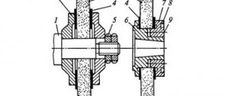
If it is necessary to grind the shoulder and the adjacent narrow journal of the stepped shaft, machines with a rotary grinding head are used. The angle of rotation depends on the allowance removed from the end and the diameter of the shaft journal and the size of the end and can be set from 8 to 45 degrees, more often 25 degrees. Such machines are called face cylindrical grinding machines (Fig. 36).
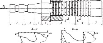
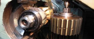
Simultaneous grinding of several surfaces using the plunge method can be carried out using a shaped wheel (Fig. 37).
Rice. 37. Scheme for grinding surfaces with a shaped wheel
A type of shaft grinding with longitudinal feed is creep-feed grinding, which is characterized by a large cutting depth (0.1...0.3 mm ) and low cutting speed.
With this grinding method, errors in the shape of the original workpiece and fluctuations in the allowance have a lesser impact on the processing accuracy compared to conventional grinding.
Therefore, deep-feed grinding is used to process workpieces without preliminary blade processing and, as a rule, the allowance is removed in one working stroke. Labor productivity increases by 1.2–1.3 times compared to longitudinal grinding.
Dimensional control during processing on grinding machines is carried out both when the machine is stopped and during operation. In the latter case, mechanical, electrical contact, electro-inductive, pneumatic, electro-pneumatic, photoelectric and other devices are widely used. The greatest effect is the use of active control, when sensors give a command to turn off the machine when a certain size is reached.
When processing parts on cylindrical and face cylindrical grinding machines, the workpieces are installed in centers, a collet, a chuck or a special device.
The workpiece is rotated at a peripheral speed of 10...50 m/min , and the peripheral speed of the grinding wheel (cutting speed) is about 30 m/s. When using stronger wheels, the cutting speed is set to 60 m/sec (high-speed grinding).
Processing modes (longitudinal feed, depth of cut) are selected depending on
grinding method,
processed material,
state of the treated surface (hardened, unhardened),
part stiffness
and other factors.
There are two methods of cylindrical grinding:
with longitudinal feed (per pass)
and with cross feed (mortise).
Processing schemes - Fig. 35.
Grinding with longitudinal feed (Fig. 35a) is used when processing cylindrical workpieces of considerable length. When grinding with longitudinal feed, the workpiece makes longitudinal movements alternately in both directions
.
The longitudinal feed is assigned depending on the type of grinding, namely: for preliminary grinding 0.5...0.8 , and for finishing (final) 0.2...0.5 of the wheel height per revolution of the part, i.e.
Spr = Sd * In kr, mm/rev.det., where
Sд - longitudinal feed of the table (workpiece) in fractions of the circle height per revolution of the part;
— Vkr — grinding wheel height, mm.
The transverse feed of the grinding wheel is carried out at the end of each stroke or double stroke of the table and is 0.005...0.02 mm (depth of cut).
At the end of processing, the last longitudinal passes are performed without cross feed ( nursing process ).
The main time when grinding with longitudinal feed is determined by the formula:
Where:
— table stroke length, mm;
— allowance per side, mm;
— rotation speed of the part, rpm;
— longitudinal feed in mm per revolution of the part;
— transverse feed of the circle per pass (double table stroke), equal to the cutting depth, mm;
— coefficient that takes into account grinding accuracy (for example: for size accuracy δ=0.1...0.15, k=1.1; for size accuracy δ=0.02...0.03, k=1.7);
The table stroke length is determined by the formula:
— during pass grinding
— when grinding at point-blank range
, Where
— length of the grinding surface, mm.
When grinding with transverse feed (Fig. 35b ), the entire surface of the part is processed at once. The height of the circle in this case should be slightly greater than the length of the workpiece surface.
The grinding wheel has only a transverse feed towards the workpiece. The advantage of this processing method is greater productivity and ease of setup, however, this method is inferior to longitudinal grinding in terms of the achieved surface quality . Plunge grinding is widely used in mass and large-scale production.
Radial (transverse) feed during final grinding S = 0.001…0.005 mm/rev .
Basic time for plunge grinding
Currently, in order to increase the productivity of the grinding process, cylindrical grinding machines with two, three or more grinding wheels have become widely used (Fig. 58).
If it is necessary to grind the shoulder and the adjacent narrow journal of the stepped shaft, machines with a rotary grinding head are used. The angle of rotation depends on the allowance removed from the end and the diameter of the shaft journal and the size of the end and can be set from 8 to 45 degrees, more often 25 degrees. Such machines are called face cylindrical grinding machines (Fig. 36).
Simultaneous grinding of several surfaces using the plunge method can be carried out using a shaped wheel (Fig. 37).
Rice. 37. Scheme for grinding surfaces with a shaped wheel
A type of shaft grinding with longitudinal feed is creep-feed grinding, which is characterized by a large cutting depth (0.1...0.3 mm ) and low cutting speed.
With this grinding method, errors in the shape of the original workpiece and fluctuations in the allowance have a lesser impact on the processing accuracy compared to conventional grinding.
Therefore, deep-feed grinding is used to process workpieces without preliminary blade processing and, as a rule, the allowance is removed in one working stroke. Labor productivity increases by 1.2–1.3 times compared to longitudinal grinding.
Dimensional control during processing on grinding machines is carried out both when the machine is stopped and during operation. In the latter case, mechanical, electrical contact, electro-inductive, pneumatic, electro-pneumatic, photoelectric and other devices are widely used. The greatest effect is the use of active control, when sensors give a command to turn off the machine when a certain size is reached.
Other metal grinding methods
There are also other, less common metal processing methods:
- Peeling – erasing the top layer if it has been damaged during use. After this, another sanding method must be used.
- Profiling is the most difficult technology, which involves working with a curve or broken line. This is the general name for gear grinding, thread grinding and spline grinding.
- Finishing – grinding, which is used to achieve shine and a polishing effect. This technology removes scratches and stains from the surface of the product.
Processing parts before grinding
Metal grinding is the final stage of processing, and it requires preliminary preparation. Before the process, it is necessary to process metal parts in several stages:
- Rough turning of the workpiece. At the first stage, the workpiece is given the required shape and dimensions, taking into account the allowance.
- Finish turning of metal. The workpiece is processed to the required size.
- Milling. This technology involves removing the workpiece mechanically. Milling is most often carried out on housing parts and gears.
- Metal processing under high temperature. The workpiece is hardened in order to significantly increase the hardness and strength of the surface. Annealing and tempering reduces the fragility of the product. In some cases, during the heat treatment process, certain chemicals are applied to the surface layer.
The Cherepovets metal structures plant has been working for you for more than 55 years. We design products, then manufacture them in our own workshops and deliver them throughout Russia. To order, call 8 or order a call on the website.