Purpose and types of broaches, their design and geometric features
Broaches are multi-tooth cutting tools used for machining holes, grooves and external surfaces with a simple or shaped contour. When cutting with broaches, only one, usually translational movement of the tool is used, the speed of which is the cutting speed. There are no feed movements, and the cutting of metal layers S. is carried out by increasing the height or width of the subsequent tooth relative to the previous broach tooth (Fig. 14.49, a).
If the cutting of layers is carried out by exceeding the height of the subsequent tooth in relation to the previous one, then such a scheme is called ordinary or single (Fig. 14.49, b).
Rice. 14.49. Schemes for cutting metal layers during broaching
If the broach teeth are divided into groups (Fig. 14.49, c), within which the teeth have the same height, but different lengths of the cutting edges of the teeth, then this pattern of cutting metal layers is called group or progressive (Fig. 14.49, c). During the cutting process, the chips are placed in the cavity between the teeth, the dimensions of which must be sufficient to completely accommodate the chips (see Fig. 14.49, a).
Pulling holes of various configurations with a closed contour is called internal broaching (Fig. 14.50, a, b, e, f) (this is the most common type of broaching), and the formation of external surfaces with an open contour using broaches is external broaching (Fig. 14.50, c , G).
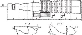
Rice. 14.50. Schemes of operation of the main types of fasteners when pulling: a - opening with a round broach, b - holes with a round broach, in the outer surface of a body of rotation with a flat broach, d - outer surface of a body of rotation with a disk broach, e - outer surface of a body of rotation with a female broach, f - inner surface bodies of rotation with a disk broach: 1 - shank, 2 - neck, 3 - transition cone. 4 - front guide part, 5 - and day guide part
The main types of internal broaches are as follows: round—for processing round holes; square - for drawing square holes from round ones; keyed - for processing a keyway in a hole; splined straight or spiral - for processing multi-keyed (splined) holes; shaped (involute, acute-angled spline, etc.) - for processing shaped profile holes; combined, etc.
The design of internal broaches provides for the following components (Fig. 14.50, a),
- shank 1 with diameter dx, length lx, intended for securing the broach in the chuck;
- neck 2 with diameter dпн, length lпн, connecting the shank with the front guide part 4 with a transition cone 3, length lнк;
- front guide 4 with diameter dпн and length lнн providing centering or direction of broaching at the initial moment of operation of the working teeth;
- working part of length lр, consisting of working teeth;
- calibrating part of length lк, consisting of 4-8 calibrating teeth;
- rear guide part 5 with diameter dzn, length designed to support and center the broach when the last teeth leave contact;
- rear shank length lts, intended for connecting the broach to the chuck on machines for automatic broaching. A broach that is pressed together is called firmware (Fig. 14.50, b).
For the manufacture of broaches, tool high-speed steels are mainly used.
The rake angles of the broaches are measured in a plane normal to the cutting edge. Recommended values of the rake angle γ (average value) depend on the material being processed and the type of teeth and are given in table. 14.28.
14.28. Recommended rake angle values for broaches, degrees
The rear angles α (Fig. 14.49) of the broaches are measured in the axial plane coinciding with the direction of movement of the broaches during broaching. The average values of the rear angles α depend on the type of broach and the purpose of the teeth on the broach (Table 14.29).
14.29. Recommended values of back angles for broaches, degrees
On the calibrating teeth of internal broaches, to maintain the size, the clearance angle on a strip 0.2–1.2 mm wide is zero or within 0.5–1°. The width of the tape on the calibrating teeth is minimal, at the first tooth it is 0.2 mm and gradually increases towards the last calibrating tooth. The calibrating teeth have no tooth lift and do not remove chips. As the cutting teeth wear and are re-sharpened, the calibrating teeth successively become cutting teeth. To reduce roughness and obtain high accuracy, several smoothing teeth are made at the end of the calibrating teeth.
On the cutting teeth of the broaches, to ensure the formation of chips and the possibility of their removal from the cavity, chip separating grooves are ground in the usual pattern or fillets in the group pattern of cutting the allowance. The angle φ between the sides of the groove is taken depending on the diameter of the broach in the range from 45 to 60°. The number of grooves on round broaches with a diameter from 10 to 80 mm is selected in the range from 6 to 36 pcs. so that the distance between them is no more than 5-7 mm. The width of the groove is 0.6–1.2 mm, the bottom of the cavity is 0.2–0.4 mm, depending on the diameter of the broach. Approximately the same dimensions of grooves are made on keyed, splined, rectangular and flat broaches. For round broaches with a group cutting pattern for processing holes with a diameter of 10-20 mm, 6-14 fillets are formed with a width of α = 4-9 mm, a radius of RB = 22.5 mm.
Topic 8.1. Pulling process
Broaching is a technological method of processing metals by cutting using special tools - broaches, broaches and broaching blocks.
Broaches
are called special tools for finishing processing (profiling) of through holes in workpieces pre-made by drilling.
Using broaches, holes of round, square and hexagonal cross-sections are produced, as well as holes with a keyway, spline and shaped holes of complex profile. Broach 1
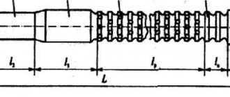
(Fig. 8.1.1) is a multi-blade metal-cutting tool that has a large length (
l≤
1500 mm) with relatively small transverse dimensions. On the cutting part l4 of the broach there is a large number of cutting teeth located one after another. When processing internal centrally symmetrical holes, the broach teeth have a ring shape of the corresponding profile. The outer size of each broach cutting tooth is larger than the size of the previous one and smaller than the size of subsequent cutting teeth. The half-difference in size (difference in height) of the last and first teeth of the cutting part of the broach is equal to the allowance for broaching processing. In addition to the cutting part, the broach has a calibrating part l5, front l3, and rear guides l6, a neck l2 and a locking part l1 intended for securing the broach in the chuck.
During the cutting process, broaching 1
(Fig. 8.1.1) with a force P applied by the traction chuck to the locking part, it is literally pulled (pulled) through a stationary workpiece
2
mounted on the support device
3
of the table 4 of the broaching machine. In this case, tensile stresses act in the broach body between the locking part and the tooth, which is currently cutting off the metal layer from the inner surface of the workpiece.
Rice. 8.1.1. Broach for pulling through the internal hole
Firmware
(Fig. 8.1.2) are tools of shorter length than broaches that have cutting teeth on the cutting part l4.
During operation, the piercings are pushed with a force P through pre-made holes and, cutting off the allowance left for processing, change their shape and size. Compressive stresses arise in the body of the firmware. For this reason, the length of the firmware is also limited, since with a large length, loss of stability may occur due to longitudinal bending. When cutting large allowances, the holes are broached sequentially with a set of broaches with an increasing external size of the teeth. The loading pattern also determines the design of the piercings, which has only a cutting part l
4 and guide parts front l3 and rear l6 (Fig. 8.1.2).
Fig.8.1.2. Firmware for pulling the internal hole
Long blocks
are called sets of prismatic broaches designed for processing the outer surfaces of workpieces.
Broaches are mounted on broaching blocks, making up a set for complete processing of external machined surfaces in one pass. For example, on the body 1 of the broaching unit (Fig. 8.1.3) there are three sections of broaches 2
, which process three surfaces simultaneously on the workpiece
3
.
Figure 8.1.3. Broaching block for broaching the outer surface
Broaching ensures the production of surfaces with low roughness, as well as sizes corresponding to 6…8 accuracy grades. Broaching is also a high-performance technological method for processing profile holes and external surfaces. With its help, you can process a large number of workpieces per shift, but only of one standard size. Therefore, broaching processing is cost-effective only in large-scale and mass production.
Principal kinematic diagram of broaching
.
Broaching is based on the use of the simplest basic kinematic cutting scheme (Fig. 8.1.4). The rectilinear main movement Dr imparted to broaching tools or workpieces can be directed along the horizontal axis x
(Figure 8.1.4,
a
) if broaching is carried out on horizontal broaching machines.
When working on vertical broaching machines, rectilinear movement is directed along the vertical axis z
(Fig. 8.1.4,
b
). The rectilinear movement Dr on the basic kinematic cutting diagram is quantitatively characterized by the cutting speed. The kinematic design of broaching machines in accordance with the basic kinematic cutting diagram provides only for the rectilinear reciprocating movement of the working bodies. Direct translational motion is always a working stroke; return movement - idling.
Fig.8.1.4. Principal kinematic diagrams for broaching:
Broaching is a technological method of processing metals by cutting using special tools - broaches, broaches and broaching blocks.
Broaches
are called special tools for finishing processing (profiling) of through holes in workpieces pre-made by drilling.
Using broaches, holes of round, square and hexagonal cross-sections are produced, as well as holes with a keyway, spline and shaped holes of complex profile. Broach 1
(Fig. 8.1.1) is a multi-blade metal-cutting tool that has a large length (
l≤
1500 mm) with relatively small transverse dimensions. On the cutting part l4 of the broach there is a large number of cutting teeth located one after another. When processing internal centrally symmetrical holes, the broach teeth have a ring shape of the corresponding profile. The outer size of each broach cutting tooth is larger than the size of the previous one and smaller than the size of subsequent cutting teeth. The half-difference in size (difference in height) of the last and first teeth of the cutting part of the broach is equal to the allowance for broaching processing. In addition to the cutting part, the broach has a calibrating part l5, front l3, and rear guides l6, a neck l2 and a locking part l1 intended for securing the broach in the chuck.
During the cutting process, broaching 1
(Fig. 8.1.1) with a force P applied by the traction chuck to the locking part, it is literally pulled (pulled) through a stationary workpiece
2
mounted on the support device
3
of the table 4 of the broaching machine. In this case, tensile stresses act in the broach body between the locking part and the tooth, which is currently cutting off the metal layer from the inner surface of the workpiece.
Rice. 8.1.1. Broach for pulling through the internal hole
Firmware
(Fig. 8.1.2) are tools of shorter length than broaches that have cutting teeth on the cutting part l4.
During operation, the piercings are pushed with a force P through pre-made holes and, cutting off the allowance left for processing, change their shape and size. Compressive stresses arise in the body of the firmware. For this reason, the length of the firmware is also limited, since with a large length, loss of stability may occur due to longitudinal bending. When cutting large allowances, the holes are broached sequentially with a set of broaches with an increasing external size of the teeth. The loading pattern also determines the design of the piercings, which has only a cutting part l
4 and guide parts front l3 and rear l6 (Fig. 8.1.2).
Fig.8.1.2. Firmware for pulling the internal hole
Long blocks
are called sets of prismatic broaches designed for processing the outer surfaces of workpieces.
Broaches are mounted on broaching blocks, making up a set for complete processing of external machined surfaces in one pass. For example, on the body 1 of the broaching unit (Fig. 8.1.3) there are three sections of broaches 2
, which process three surfaces simultaneously on the workpiece
3
.
Figure 8.1.3. Broaching block for broaching the outer surface
Broaching ensures the production of surfaces with low roughness, as well as sizes corresponding to 6…8 accuracy grades. Broaching is also a high-performance technological method for processing profile holes and external surfaces. With its help, you can process a large number of workpieces per shift, but only of one standard size. Therefore, broaching processing is cost-effective only in large-scale and mass production.
Principal kinematic diagram of broaching
.
Broaching is based on the use of the simplest basic kinematic cutting scheme (Fig. 8.1.4). The rectilinear main movement Dr imparted to broaching tools or workpieces can be directed along the horizontal axis x
(Figure 8.1.4,
a
) if broaching is carried out on horizontal broaching machines.
When working on vertical broaching machines, rectilinear movement is directed along the vertical axis z
(Fig. 8.1.4,
b
). The rectilinear movement Dr on the basic kinematic cutting diagram is quantitatively characterized by the cutting speed. The kinematic design of broaching machines in accordance with the basic kinematic cutting diagram provides only for the rectilinear reciprocating movement of the working bodies. Direct translational motion is always a working stroke; return movement - idling.
Fig.8.1.4. Principal kinematic diagrams for broaching:
Wear of broach teeth
Wear of the broach teeth occurs along all surfaces of contact with the workpiece and chips during the cutting process: along the front h and rear h surfaces, along the corners hу and transition cutting edges, along the strip of calibrating teeth (Fig. 14.51, a, c). The limiting wear is the wear of the rear surface hз and hy (Fig. 14.51, d) and the rounding of the edge of the broach tooth.
Rice. 14.51. Wear pattern of broach teeth: a, b - keyed broaches, respectively, without chip separating grooves and with them, c - round broach with chip separating grooves, d - wear on the front and rear surfaces and rounding of the cutting edge of the broach tooth
The permissible amount of wear on the rear surface of the broach teeth hz is in the range of 0.10–0.15 mm, and on the corners of the chip separating grooves – 0.2–0.4 mm. The rounding of the cutting edge occurs unevenly: it is somewhat more intense in the initial period and stabilizes in the subsequent period of work. Excessive rounding of the edge causes an increase in surface roughness and changes in the size and shape of the drawn holes. Therefore, the permissible values of wear on the flank surface and rounding of the cutting edge are determined by the technological requirements for the quality of the surface of the parts.
Machining of flat surfaces by broaching
Due to its high productivity and low processing costs, broaching of external flat surfaces (as well as shaped ones) is increasingly used in large-scale and mass production; This method is economically beneficial, despite the high cost of equipment and tools. Many operations are performed by external broaching instead of milling. Such operations include broaching of grooves, grooves, planes of engine blocks and other parts, gear teeth, etc. When machining by broaching external black (not pre-treated) surfaces, high precision and surface cleanliness are achieved in one broaching stroke. During the processing process, each cutting tooth of the broach removes a layer of metal that forms part of the allowance, and the calibrating teeth clean the surface, while they do not lose their cutting ability and shape for a long time.
Rice. 7. Schemes of flat broaches: a
- ordinary;
6, c, d
- progressive.
When processing black surfaces of forgings and castings, it is more advisable to use non-ordinary flat broaches (Fig. 7, a),
aprogressive (Fig. 7, b,
c, d).
With conventional flat broaches, each tooth removes chips across the entire width of the machined surface; therefore, when processing a black surface having. crust, the first teeth of the broach quickly become dull or chipped. In progressive broaches, the cutting teeth are made of variable width, gradually increasing, and each cutting tooth cuts the metal not across the entire width of the surface being processed, but in stripes, and the width of these strips increases with each tooth, and only the calibrating teeth clean the surface being processed across its entire width.
For processing by external pulling of wide planes (more than 50 mm)
install several broaches side by side.
Broaching of external surfaces is mostly done on vertical broaching machines - semi-automatic and automatic. In Fig. Figure 8 shows parts whose surfaces are processed by external drawing (the processed surfaces are indicated by the letter ).
Rice. 8. Parts processed by broaches
The use of external pulling for processing flats at the ends of the roller is shown in Fig. 9, a.
Two rollers are processed simultaneously;
Each roller is processed with two broaches. In Fig. 9, b
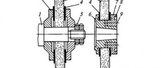
shows a diagram of pulling the cap and connecting rod head of an automobile engine.
The cylindrical surface of the lid is pulled by round broaches 1 and 3,
which, as one half becomes blunt, are rotated 180°, and the other half comes into operation.
Broaches 2
and
4
process the surfaces of the cover connector.
The connecting rod head is processed with broaches 5,6,7
and
8.
Broaches are made of three sections along the length - roughing, semi-finishing and calibrating. After wear, the calibration section is ground and placed in place of the finishing floor, and the finishing section is placed in place of the roughing section.
In mass production, high-performance continuous broaching machines are used. Chain drive machines have a chain that rotates on sprockets (like a tractor track) that moves parts attached to it; When the chain moves the parts past the broaches located at the top of the machine, the broaches remove chips from the surface being machined.
Rice. 9. Pulling schemes:
V
— bald spots on the rollers;
6
— caps and connecting rod heads
On continuous machines with a rotary table (Fig. 10, a) or with a drum (Fig. 10, b), around the circumference of which parts 1 are located in fixtures, the table or drum, when rotating, moves the parts past the broaches 2,
which process the surfaces of parts.
Rice. 10. Schemes of operation of machines for continuous broaching with a rotary table:
1 - processed parts; 2 - broach
Due to its high productivity and low processing costs, broaching of external flat surfaces (as well as shaped ones) is increasingly used in large-scale and mass production; This method is economically beneficial, despite the high cost of equipment and tools. Many operations are performed by external broaching instead of milling. Such operations include broaching of grooves, grooves, planes of engine blocks and other parts, gear teeth, etc. When machining by broaching external black (not pre-treated) surfaces, high precision and surface cleanliness are achieved in one broaching stroke. During the processing process, each cutting tooth of the broach removes a layer of metal that forms part of the allowance, and the calibrating teeth clean the surface, while they do not lose their cutting ability and shape for a long time.
Rice. 7. Schemes of flat broaches: a
- ordinary;
6, c, d
- progressive.
When processing black surfaces of forgings and castings, it is more advisable to use non-ordinary flat broaches (Fig. 7, a),
aprogressive (Fig. 7, b,
c, d).
With conventional flat broaches, each tooth removes chips across the entire width of the machined surface; therefore, when processing a black surface having. crust, the first teeth of the broach quickly become dull or chipped. In progressive broaches, the cutting teeth are made of variable width, gradually increasing, and each cutting tooth cuts the metal not across the entire width of the surface being processed, but in stripes, and the width of these strips increases with each tooth, and only the calibrating teeth clean the surface being processed across its entire width.
For processing by external pulling of wide planes (more than 50 mm)
install several broaches side by side.
Broaching of external surfaces is mostly done on vertical broaching machines - semi-automatic and automatic. In Fig. Figure 8 shows parts whose surfaces are processed by external drawing (the processed surfaces are indicated by the letter ).
Rice. 8. Parts processed by broaches
The use of external pulling for processing flats at the ends of the roller is shown in Fig. 9, a.
Two rollers are processed simultaneously;
Each roller is processed with two broaches. In Fig. 9, b
shows a diagram of pulling the cap and connecting rod head of an automobile engine.
The cylindrical surface of the lid is pulled by round broaches 1 and 3,
which, as one half becomes blunt, are rotated 180°, and the other half comes into operation.
Broaches 2
and
4
process the surfaces of the cover connector.
The connecting rod head is processed with broaches 5,6,7
and
8.
Broaches are made of three sections along the length - roughing, semi-finishing and calibrating. After wear, the calibration section is ground and placed in place of the finishing floor, and the finishing section is placed in place of the roughing section.
In mass production, high-performance continuous broaching machines are used. Chain drive machines have a chain that rotates on sprockets (like a tractor track) that moves parts attached to it; When the chain moves the parts past the broaches located at the top of the machine, the broaches remove chips from the surface being machined.
Rice. 9. Pulling schemes:
V
— bald spots on the rollers;
6
— caps and connecting rod heads
On continuous machines with a rotary table (Fig. 10, a) or with a drum (Fig. 10, b), around the circumference of which parts 1 are located in fixtures, the table or drum, when rotating, moves the parts past the broaches 2,
which process the surfaces of parts.
Rice. 10. Schemes of operation of machines for continuous broaching with a rotary table:
1 - processed parts; 2 - broach
Digital library
General technical disciplines / Cutting tools / 5.3. Schemes for cutting off allowance when broaching
When designing broaches, profile, generator and progressive (group) cutting schemes (cutting allowance) are used. In Fig. Figure 5.4 shows cutting patterns for some typical broaching operations.
According to the profile scheme
Each cutting tooth of the broach cuts relatively thin and wide layers of material parallel to the machined surface. This scheme is used mainly for broaches that process surfaces of simple shapes, such as cylindrical ones, since making an accurate profile on all broach teeth of different sizes and sharpening them is difficult.
When working with a progressive (group) scheme
When cutting, a wide layer of metal is removed not by each tooth, but by a group of several (2...5) teeth having the same diameter or height, with the first teeth cutting grooves in the metal, and the subsequent ones cutting spaces. Each tooth cuts narrow but thicker chips than with a profile pattern. The treated surface is finally shaped by teeth working according to a profile pattern.
Step (generator) circuit
broaching is characterized by cutting off the allowance in relatively narrow layers located perpendicular or oblique to the machined surface. The allowance is cut off using cutting teeth that have a variable profile, gradually moving from a straight or round shape to a given profile. The final formation of the surface of the product is carried out by teeth having a profile that matches the specified one. The advantage of generator broaches is their manufacturability, the disadvantage is the lower accuracy of the product profile compared to the profile circuit.
Broaches for processing planes and cylindrical holes using a profile scheme are structurally and technologically simpler than using progressive and generator schemes. Square and hexagonal, as well as flat broaches for shaped surfaces, made according to the generator principle, are easier to manufacture than broaches of a conventional design (profile).
On the other hand, you should also keep in mind the operating conditions of the broaches. For example, the teeth of a flat broach of an ordinary design are chipped when working on the crust, but according to the generator circuit, cutting the crust across, they resist chipping well.
Cylindrical broaches with a progressive cutting pattern cut thicker chips and produce shorter chips.
In many cases of broaching complex surfaces, individual sections of them are formed according to a profile scheme, others - according to a generator scheme, i.e.
combined. For example, when drawing keyways and spline holes, the bottom of the grooves is formed according to a profile pattern, and the sides - according to a generator pattern.
Allowances when broaching are selected depending on the type of broaching and the quality of the preliminary hole. There is an allowance for side A and an allowance for the diameter: (Fig. 5.5).
When processing cylindrical holes with broaches, the value, depending on the diameter and length of broaching, varies from 0.3 to 1.6 mm; for flat broaches during roughing mm, after pre-processing - mm.
The diameter of the preliminary hole is defined as
, where is the diameter of the final hole, which is equal to - for holes H7 and H9 and - for holes made according to H10 and coarser.
For faceted holes, the profile of which is formed by straight lines, the smallest processing diameter is assumed to be equal to the diameter of the inscribed circle (Fig. 5.5b).
Rice. 5.4. Schemes for cutting off allowance when broaching
Rice. 5.5. Allowances when drawing various types of holes:
a – round hole; b – slotted hole; c – faceted hole
Features of broach design
The properties of the processed material significantly influence the cut chips and their shape. When cutting ductile metals, it is usually curled into a spiral roller, which is placed in the active, or working, part of the groove, and when processing brittle materials, cast iron, bronze and others, the fracture chips are cut off by separate elements that fill the entire space of the groove, including its non-working volume. Based on these features, the following groove profiles are currently used:
— The two-radius shape ensures good formation of chips into a dense bead, economical filling of the groove with chips and their removal when processing plastic materials, even with large cut thicknesses (up to 0.4 mm).
— A single-radius shape with a flat tooth back is easy to manufacture, but chips can jam in it, so it is used for profile broaches that have relatively small lifts per tooth when processing steel, as well as for broaches with other cutting patterns when processing materials such as cast iron.
— Double-radius special shape with flute projections ensures good chip removal when machining at high cutting speeds.
-. The two-radius elongated shape with a straight section at the bottom of the groove is used when processing very long parts. The rollers formed here are placed one after another in the broach groove.
— The elongated single-radius shape with a flat back is easy to manufacture and has proven itself well for broaches used when processing long parts made of brittle metal.
The pitch of the roughing teeth and other geometric parameters of the broaching chip groove are selected based on the conditions of the normal process of filling chips in the broaching groove. When processing plastic materials, the cut chips are rolled into a flat spiral and placed in the active part of the groove; the groove depth and pitch are calculated based on the fill factor, the value of which is determined from the ratio of the areas or volumes of the active part of the groove to the area or volume of the layer being cut.
The fill factor value is usually determined experimentally. The value of the coefficient depends on the properties of the material, the thickness of the cut, the size and shape of the groove. For profile broaches, when the cut chips receive a stiffening rib from the chip separator of the previous tooth, this prevents the chips from curling into a roller; the filling factor is 25% greater than for group broaches, where it varies from 2.5 to 3.3. In addition, when processing steels with increasing cut thickness, the coefficient k for profile broaches increases, and for group broaches it decreases. For cast iron, bronze and other brittle metals, this effect is insignificant and the coefficient k varies from 1.8 to 2.5.
When determining the pitch of the broaching teeth, in addition to recommendations related to the selection of the size and shape of the grooves, the following requirements must be taken into account.
1. The geometric parameters of the cutting elements of the tooth must ensure maximum broaching resistance.
2. The tooth must have the maximum number of grinds.
3. The tooth must be strong enough not to be destroyed under the influence of bending tangential cutting force.
Geometric parameters of broach teeth. The value of the rake angle y = 5-25° is set depending on the properties of the material being processed, as well as the material of the broach, although currently most broaches are made from high-speed steels R9, R12, R18, R6M5 and other grades.
An increase in the rake angle from 5 to 15° when broaching steel increases the durability of high-speed broaches, according to ChTZ, by 20-25%, and with lift values per tooth over 0.05 mm, it helps to reduce the cutting force. Angle y also affects the steepness of the chip rollers. The back angle of the teeth of internal broaches is taken regardless of the properties of the material being pulled. The determining factor here is the need to maintain their working dimensions when grinding the teeth.
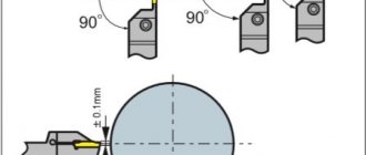
The presence of a strip with zero clearance angle on the broach teeth has a significant effect on increasing the friction forces of the tooth on the machined surface and also on increasing the cutting forces. Therefore, it is recommended to sharpen the cutting teeth to a point, and to facilitate the sharpening process, it is recommended to leave a chamfer with a width of no more than 0.02-0.03 mm. On calibrating teeth, the chamfer size should be no more than 0.2 mm.
For external broaches, the installation of which can be easily adjusted to a certain size, to increase durability, the rear angles on the cutting teeth can be increased to 6-10 degrees.
Cutting patterns when broaching
The design of the working part of the broach and its performance depend on the size of the metal layers being cut and the order of their cutting from different sections of the processed profile, i.e., on the adopted single or group cutting schemes.
Currently, when broaching, two types of single cutting patterns are used: profile, generator, and also several options for group (progressive) cutting patterns.
In broaches with a profile cutting pattern, all teeth are similar to the profile of the broached part and thin parallel layers of metal are cut due to the height of the next tooth being higher than the previous one.
The generator cutting scheme provides for the formation of a given contour of the drawn surface by a gradual transition from simple to complex blades. The main allowance is usually cut with teeth that have a straight or circular profile, which greatly simplifies the production of broaches. The simple profile of the individual teeth of the broaches makes it possible to change the thickness of the cut so that teeth with short blades have more lift, as a result of which the broach length can be reduced. In addition, sharpening the broach is simplified and the strength of individual sections of the blade increases. The required profile on the product is formed by auxiliary cutting blades, and the final cleaning of the surface is carried out by finishing teeth having a profile of the treated surface. Thus, the finishing and calibrating teeth of these broaches are carried out according to the cutting profile. The generator cutting circuit consists of square and conventional splined internal broaches, as well as conventional flat and shaped external broaches.
The disadvantage of generator broaches is most often their reduced durability due to the unfavorable geometry of the tooth angles, and in some cases they give lower accuracy of the processed part profile. Generator broaches are used mainly when processing surfaces of complex shapes, when the use of group broaches is unprofitable.
Options for group cutting broaches. The group cutting scheme is characterized by the fact that the metal layers along the entire profile are cut not by each tooth, but by a group or section of 2-5 teeth. In this case, the first (slotted) teeth of the section cut grooves in the metal, and the last (cleaning) tooth cuts off the remaining protrusions. Chip separation here is achieved due to backed fillets, chamfers, flats and other structural elements of the adopted version of the group cutting scheme, therefore there is no need to manufacture special chip separation grooves, as is required for broaches of a profile cutting scheme. The use of group cutting broaches reduces the number of cutting teeth and the length of the broach as a whole due to a sharp increase in the thickness of the cut layer by a section of teeth.
When processing holes of relatively small diameters, as well as when processing holes of large length, when due to insufficient traction force of the machine or the strength of the broach, the amount of lift per section is limited, it is more advisable to use broaches of a multifaceted cutting pattern. The roughing teeth of these broaches also consist of sections. The formation of individual sections of the cutting blades is carried out using back flats, which are arranged in a checkerboard pattern on the slotted teeth of each section. The presence of shallower backed flats instead of fillets with the same length of cutting sections of the tooth makes it possible to reduce the labor intensity of manufacturing broaches, since the formation of flats can be done not only by grinding, but also by more productive preliminary milling with transverse feed. In addition, during final grinding of flats, due to the small allowance, burns on the blades are reduced and the durability of the broaches increases. When processing spline surfaces of various shapes, broaching is the best process. In this case, splined broaches of a group cutting pattern are most widely used, and vice versa, splined broaches of a generator circuit are used very rarely. This is related to that. that generator spline broaches have a small (up to 0.15 mm) rise per tooth and the teeth cut chips across the entire width of the spline. In this case, processing due to small lifts per tooth is usually carried out with a set of broaches. In addition, the absence of an auxiliary clearance angle leads to increased wear of the tooth corners and a surface of a low cleanliness class.
When processing spline holes, broaches made according to various variants of a group cutting pattern - the presence of two teeth in a section - have proven themselves well. The first, or slotted, tooth, the length of the main blade of which is more than half the width of the slot, cuts off the main part of the allowance. The cutting areas are created using relief chamfers, fillets or flats. The second (cleaning) tooth cuts off the metal on both sides only in the corners, i.e., in narrow areas 0.5-2 mm wide, and the width of the slots is finally formed. To prevent the cutting tooth from cutting chips across the entire width of the slot, its diameter is usually made 0.04 mm smaller than the diameter of the slotted tooth. In addition, the angles of the slotted teeth have a favorable geometry. In addition, the chips that are not cut across the entire width of the spline do not have friction on the sides of the splines and curl freely in a two-radius groove. It also makes it easier to remove narrow chips cut off by the corners of the grinding tooth, which has very small lateral chamfers (up to 0.6-0.8 mm). Therefore, it is possible to significantly increase the thickness of the cut layer with each tooth, as a result of which the broach length will decrease.
Despite some similarity in the design of the cutting elements of the teeth and the nature of the cut layer, it is advisable to use the above variants of the group scheme of splined broaches taking into account the following recommendations.
Some of the variants of the group cutting pattern (alternating cutting and trapezoidal) are also widely used when processing planes and open external surfaces. Due to the fact that external broaching is most often performed when removing large allowances along the crust, reducing the length of a set of broaches by choosing a rational scheme is of particular interest. The variable cutting scheme should be used only for those broaches that must be sharpened along the front surface, since when sharpening along the back surface, the depth of the fillets decreases and after several resharpenings they need to be restored. Broaches, the installation of which can be easily ensured to a certain size, are advisable to resharpen along both the front and rear surfaces.
The broach of a trapezoidal cutting pattern usually consists of two sections (parts) installed on a common tool plate. In each section, a lift of s> = 0.l -1.0 mm is carried out per tooth. In this case, the teeth in the two sections have the same height and only the last tooth of the second section is lowered by 0.02-0.04 mm compared to the last tooth of the first broach section. The first section, which is like a short splined broach, cuts narrow trapezoidal grooves in the allowance to be removed, and the second, with straight or circular blades, cuts off the remaining metal protrusions to form a plane or cylindrical surface.
Due to the large lifts per tooth, the length of each section does not exceed 250 mm. The durability of this broach is much higher than that of profile broaches. This is facilitated by increased apex angles and the presence of positive rear angles a; on the side blades of trapezoidal teeth, which are formed when grinding and sharpening trapezoidal splines along the rear surface to pass with the rear end of the broach raised by 1-1.5 mm. A broach with a trapezoidal cutting pattern is very simple to manufacture and allows for a large number of resharpenings, but it can be used for large allowances and rough work.
Based on materials: Zhigalka N. I., Kiselev V. V. design and production of cutting tools.
Litstamp Tools and Equipment
The cutting pattern when broaching is the order in which the work of cutting the allowance is distributed between the broaching teeth. When choosing a cutting scheme, it is necessary to take into account a number of requirements that provide the best conditions for broaching. These requirements boil down mainly to the following: 1) use as large feeds per tooth as possible; 2) ensuring the shortest pulling length; 3) achieving accuracy and cleanliness of the processed surface; 4) better chip formation and corresponding geometry on the main and auxiliary cutting edges.When processing a workpiece using a broach, the teeth of the latter can cut off a given allowance in different sequences: immediately along the entire contour, in transverse layers, or along a specific part of the contour. Each of these processes of cutting allowance is predetermined by its own cutting pattern. The choice of cutting pattern depends on the shape and size of the drawn parts. The appropriate choice of cutting pattern determines the length of the broach, its durability and manufacturability, i.e., in general, the productivity and efficiency of broaching. Currently, three cutting schemes are used: 1) profile (single cutting), 2) generator and 3) progressive (group cutting). The first two cutting schemes are single cutting methods, the third is group cutting. The profile cutting scheme is characterized by the fact that each cutting tooth of the broach removes metal from the entire processed contour, cutting off a layer of thickness a due to the height of the previous tooth exceeding the next one. It is based on cutting with each cutting tooth of a broach relatively thin and wide layers of metal parallel to the machined surface. The cutting edges are also parallel to this surface and do not participate in its construction, except for the last cutting tooth, which forms the machined surface. Three cases of using this cutting scheme during processing are presented: plane (a), shaped surface (b) and shaped hole (c).
The generator cutting scheme is characterized by cutting off the allowance in relatively narrow layers located perpendicularly or obliquely to the machined surface. With this scheme, each cutting tooth, cutting off the allowance, simultaneously participates in the construction of the machined surface, which is obtained as a result of the closure of a number of narrow elementary surfaces processed by individual broach teeth. In Fig. 167 presents three cases of using this cutting scheme during processing: a plane (a), a shaped surface (b) and a shaped hole (c). The progressive (group) cutting scheme is characterized by the fact that individual wide layers of metal are cut here not by each broach tooth, but by a group of several teeth. The teeth within a group have the same diameters or heights and cut a common layer of thickness a due to the widening of the cutting edge of the next tooth in the group in relation to the previous one. Each cutting tooth here accounts for narrow and much thicker chips than with the profile scheme. The machined surface is built by the last group of cutting teeth or teeth working according to a profile pattern. Three cases of using this cutting scheme during processing are presented: plane (a), shaped surface (b) and shaped hole (c). Each tooth of the section forms only a certain section of the contour. Despite the fact that all the teeth of the sections nominally have the same height or diameter, on the last tooth of each section they are reduced by 0.04-^0.02 mm compared to the rest, so that in the event of elastic deformation of the material processed by the first teeth of the group, the last the tooth would not cut any debris on the cutting edges of the previous teeth and thus would not create undivided chips.
The cutting blades on the remaining teeth of the section are formed by removing the unnecessary part of the blade from the complete working profile of the tooth. To do this, separating devices are created on the teeth in the form of splines, flats, fillets or chamfers, arranged in a checkerboard pattern or in other combinations, as described above. Depending on the separating devices used, the group cutting scheme receives various options for its implementation: checkerboard, variable cutting, multifaceted, Yunkin scheme, trapezoidal and a number of others. Checkerboard version of the group cutting pattern. In this group design, the first teeth of each section are equipped with splined projections /, and the last teeth of section 2 are round without projections, but with a reduced diameter. In cases where there are several teeth in a section, the splined projections on adjacent teeth are mutually offset. Finishing teeth are designed with a lift per tooth and chip separating grooves, like those of profile cutting broaches. The advantages of this scheme include the fact that it allows large feeds and reduces the broaching length, but at the same time, the absence of a clearance angle on the sides of the spline protrusions creates additional friction and reduces the broaching work. The variant of variable cutting of the group scheme has rough teeth working in sections, but the non-relief spline protrusions are replaced by wide backed fillets.
The fillets ensure the creation of an increased angle e between the main and auxiliary cutting edges, as well as a rear angle in the transition and auxiliary areas. The finishing teeth here are also equipped with backed fillets, replacing chip separating grooves.
The disadvantage of this version of the group cutting scheme is that the fillets on the teeth in some cases turn out to be small and in some cases too deep and wide, especially with a small number of splines.
Previous articles:
- Broaching is one of the most effective operations for processing materials by cutting, which is done using a broaching cutting tool. This operation...
“>Manufacture of broaches according to GOST
- Manufacturing of broaches
- Broaching tool
- Broaches GOST
- Prefabricated broaches
Similar articles:
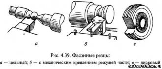
- When working on a milling machine, shaped cutters with a cutting edge are used; with such cutters it is relatively easy to process parts with high accuracy...
">Shaped cutters
- By design, thread cutters are divided into disk (single-thread) and cylindrical (comb), which are like a set of disk threads...
">Thread cutters
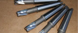
- A reamer is a metalworking tool for creating precise hole sizes. This process is called deployment. They can be used…
">Sweeps
- Broaching Broaching is a processing method or process in which a multi-edged metal-cutting tool is used to remove material - ...
«>broaching tools (metalworking)
- A milling cutter is a rotating multi-toothed tool, the cutting teeth of which come into operation sequentially, one after the other. The feed is performed by moving...
">Cutters
Next articles:
- Broaches are used to process through holes and external surfaces of various parts, and broaches are used only for through holes. Broaching work...
"> Broaches and firmware
- Metal-cutting tools The relationship between the structural and cutting elements of tools and the basic laws of metal cutting The work of tools…
">Relationship of cutting elements
- Production and manufacture of cutting tools General definitions of structural elements of cutting tools Main features of individual types of r...
">General definitions of cutting tools
- Production and production of hob cutters The production of hob cutters requires special control over product quality, since the slightest inaccuracy in…
">Production of hobs
- Milling equipment With the development of machine tool industry, one of its most promising branches has become the production of milling equipment designed…
">Manufacture of milling equipment
Next page >>