How are operating strength indicators calculated?
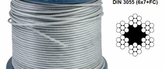
The strength of cables and ropes for production purposes is regulated by the relevant GOSTs:
- GOST 2688-80 – steel ropes, cables, slings for cranes (construction, metallurgical), installations in mines;
- GOST 3068-88 – ropes and cables for road, construction equipment, lifting and transport mechanisms, earth-moving equipment;
- GOST 7668-80 – universal steel cables for metallurgical, industrial lifting works, construction;
- GOST 7669-80 – cables and ropes for winches, excavator buckets, mine hoists;
The strength of a steel cable is determined by two criteria:
- tensile strength of cables is a calculated value that determines at what minimum loads the steel cable begins to fail;
- working strength or permissible force is an indicator of operational capabilities, optimal loads on the cable under which it can be operated for a certain period without breaks or destruction. This indicator determines what working loads are permissible for a steel rope.
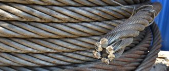
Tensile and working strength depends on production technology, design, and degree of rigidity. The higher the rigidity of the cable, the higher the tensile strength.
Tensile strength parameters of steel cables
To establish what load a steel cable can withstand, it is important to take into account that its choice is determined by two main parameters - breaking and working strength.
Read also: Dishes with pork ham on the bone
Tensile strength
Breaking strength refers to the minimum force on a rope at which it will break. If it is necessary to determine this value of a steel cable, the tensile characteristics are taken from GOST or determined using the formula:
R=Kd2, where
- K – safety factor;
- d – diameter, mm.
The coefficient K when calculating the breaking load of cables is unchanged and is selected depending on the type of specific product. So, if you need to find out the value of a single-strand type product, use the figure 70. For a rope with one organic core, take the number 40, with several cores - 34.
Application area
The use of steel rope can be found in various fields. This can be as a cable for mounting a tent and cable-stayed roof structures to suspension bridges and television and radio towers.
Different applications for wire ropes place different demands on strength, abrasion and corrosion resistance. To meet these requirements, the cable is made of materials such as:
- Stainless steel. Used where corrosion is a major factor.
- Galvanized carbon steel. It is used where strength comes first and corrosion resistance is less important.
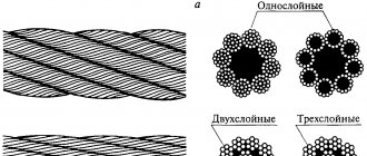
The wire (one element) can have a cross-section of up to 3 mm. This is enough to withstand loads of up to 200 kgf/mm2. Steel cables and ropes differ in terms of lay, which can be single, double or triple. The arrangement of the wire in different layers has one of the following tangents:
- point (usually used for minor intermittent loads);
- linear (used in many areas);
- point-linear (used for additional strength).
Classification of steel ropes
Depending on the type of laying of the strands, the following types of steel ropes are distinguished:
- The wires between the layers have a point contact - TK;
- Between the layers of wire there is a linear contact - LC;
- Linear contact and the same diameter of wires in each layer of the strand - LK-O;
- Linear contact and the presence of wires of different diameters in the outer layer - LK-R;
- Linear contact between filling wires and individual layers - LK-Z;
- Linear contact and the presence of strands with both wires of the same and different diameters - LK-RO;
- Combined point-linear contact of wires - TLC.
To work on drums and blocks with semicircular grooves, it is better to choose steel ropes with a linear touch. This is due to the fact that their service life is almost twice as long as that of TKL brand ropes.
Depending on the core material used, there are:
- Ropes with an organic core made from synthetic or natural materials – O.S. This type of core, thanks to its special impregnation, prevents rapid abrasion of the wires and protects the internal parts of the rope from corrosive processes;
- Ropes with a metal core – M.S. This type of steel rope is excellent for use in hot shops, as well as in cases where multi-layer winding on a drum is used.
According to the laying method, the following types of ropes are distinguished:
- Non-unwinding - N. In them, the strands retain their properties after the welding and dressing are removed from the end of the rope;
- Unwinding - R. In ropes of this type, after removing the welding or tying, the wires and strands change their position.
When making non-unwinding ropes, the wires are subjected to preliminary bending. Thanks to this, this type has greater durability, less tendency to form loops and knots, as well as torsion.
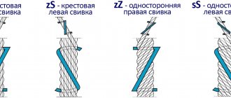
Depending on the direction of lay, steel ropes of left (L) and right (R) lay are distinguished.
There are various options for laying elements and the rope itself in triple and double lay products. In accordance with this, steel ropes are distinguished:
- One-way lay - O. They have the same direction of lay of the strands and lay of the rope itself along the outer wire.
- Cross lay. They are characterized by the opposite direction of laying of strands and strands and laying of the rope. For triple lay ropes, only this type of lay is used.
- Combined lay - K. The direction of lay of the strands alternates through one strand.
Products with cross lay are recommended for working ropes on blocks with wedge-shaped grooves or with an undercut, flat rims, as well as for cranes. In cases where the possibility of rope torsion is excluded, it is better to use ropes with one-sided lay.
Steel ropes also differ in degree of twist:
- MK - low-rotating. They are characterized by the presence of opposite direction of laying of individual elements in layers.
- Twisting - have the same direction of all strands in the strand.
Depending on the physical and mechanical characteristics of the wire, the following types of steel ropes are distinguished:
- Brand B. These ropes are used exclusively in particularly complex and critical cases.
- Grade I. Most often used as crane rope.
- Mark II.
Also, depending on the characteristics of the wire surface coating, steel ropes are classified into the following types:
- Without any coating;
- With zinc coating - coolant. Used to work in conditions with a particularly aggressive external environment;
- With zinc coating and designed for work in aggressive environments – F;
- With zinc coating for operation in medium aggressive environmental conditions – C;
- With coating of strands or the rope itself with artificial materials - P.
Steel ropes intended for cargo purposes are marked GL, and for cargo purposes - G.
According to manufacturing accuracy, ropes with increased T and normal H accuracy are distinguished.
Example of rope symbols
Surface Density of Zinc Steel Rope
| Nominal diameter, mm | Surface density of zinc, g/m2, not less, for wire groups | ||
| WITH | AND | coolant | |
| 0.20 to 0.24 | 15 | 20 | 30 |
| >0.24 to 0.32 | 20 | 25 | 45 |
| >0.32 to 0.38 | 20 | 25 | 60 |
| >0.38 to 0.45 | 30 | 40 | 75 |
| >0.45 to 0.55 | 35 | 40 | 90 |
| >0.55 to 0.65 | 40 | 50 | 110 |
| >0.65 to 0.75 | 40 | 60 | 120 |
| >0.75 to 0.95 | 50 | 70 | 130 |
| >0.95 to 1.15 | 60 | 80 | 150 |
| >1.15 to 1.40 | 60 | 90 | 165 |
| >1.40 to 1.80 | 70 | 100 | 180 |
| >1.80 to 2.40 | 80 | 110 | 205 |
| >2.40 to 3.00 | 90 | 125 | 230 |
| >3.00 to 3.80 | 100 | 135 | 230 |
| >3.80 to 4.40 | 110 | 150 | 245 |
| >4.40 to 5.10 | 110 | 165 | 245 |
Direction and combination of lay directions of steel rope:
When installing ropes, the main requirement is to prevent them from unwinding. To do this you need the following:
- The drum with the rope should be placed on the unwinding device so that its axis is strictly horizontal.
- The winding end should be located at the top or bottom of the drum.
- The drum should slow down slightly during the winding process.
- The distance between two drums must be greater than three hundred diameters of the steel rope.
During installation, rope kinks, especially alternating ones, should be avoided.
How to measure rope diameter
“Nominal Diameter” defines the design diameter of the rope. In order to measure the actual diameter, you must use a caliper, the length of the jaws of which must be more than ¾ of the diameter of the rope being measured.
Measurements should be taken in two cross sections located at a distance of at least one meter from each other. At each of these points, measurements are taken in two planes perpendicular to each other. After receiving all four results, their arithmetic mean is calculated. For a new rope, the resulting figure should be located within the tolerance field of the “nominal” diameter.
Unwinding rope from a coil
The coil should be placed on the ground and the rope should begin to unwind strictly in a straight line, while trying to prevent contamination of its surface with moisture, metal chips, soil or any other harmful substances.
The coil can also be installed on a rotary unwinder. After this, the coil is rotated by pulling the outer end of the rope.
It is impossible to unwind ropes from fixed coils, as this leads to the formation of loops and twisting of the ropes, and this in turn significantly reduces their performance.
Picture 1.
Never unwind a rope from a fixed coil, as this may cause the rope to twist and form loops, which will significantly reduce the performance of the rope (Fig. 2).
Figure 2.
Wrong.
Note the formation of loops.
Permissible load when using steel cable
The permissible load (AM) of steel ropes is calculated depending on their diameter. This value is measured in kilonewtons, with 1 kN equaling 100 kg. The permissible value for steel cables of different diameters is calculated as follows:
- for a rope with a diameter of 2 mm this value will be 0.47 kN;
- a product with a diameter of 3 mm has an allowable value of 1.06 kN;
- a thickness of 4 mm determines a DN of 1.88 kN;
- for a diameter of 5 mm this value will be 2.94 kN;
- with a thickness of 6 mm, the permissible value is 4.24 kN;
- a thickness of 8 mm determines a load of 7.52 kN;
- for a rope with a thickness of 10 mm, the DN is 1.74 kN.
The breaking load (FL) (the force required to break the cable) will also depend on the diameter of the product:
- for a rope with a diameter of 2 mm, the breaking load will be 2.35 kN;
- a product with a thickness of 3 mm has a pH of 5.29 kN;
- a thickness of 4 mm determines a breaking force of 9.41 kN;
- for a cable with a thickness of 5 mm this value will be 14.70 kN;
- with a product thickness of 6 mm, the pH is equal to 21.20 kN;
- a diameter of 8 mm determines a load of 37.60 kN;
- for a 10 mm product, pH is equal to 58.80 kN.
That is, with an acceptable value of 47 to 174 kg, steel cables with a diameter of 2 to 10 mm will last a long period of time without breaking the product or its parts. And the smallest load that is needed to destroy a cable ranges from 235 to 5880 kg for steel ropes with a diameter of 10 mm.