ATTENTION. Update your browser! Our site does not work correctly with IE 8 and older versions.
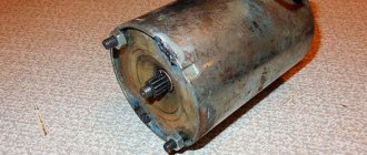
Friends, pilots, does anyone have the equipment and qualifications to make a part:
Actually an endless propeller. length 220 mm. needed for the cable guide for the winch. There is a CAD model for the CNC machine in Unigraphics. (can be converted into anything) small-scale production possible (5 pcs) Material - any steel. (If anything, the material is available) it would cost 800 rubles per piece.
THANKS TO ALL. DETAIL MADE. . . . . . . .
Two-way screws worked as stackers on the Filin passives. As a manufacturer of these winches, I will say that about
Neither work well, but their resource is limited. Or rather, not the screw itself, but a fork that switches the direction of movement of the carriage. First, the fork wears out, then the internal diameter of the carriage moves away, the carriage appears to play on the shaft, and the worst thing is when the fork jams, it breaks and breaks the screw. Making a shaft is not difficult - a simple 1K62 lathe is enough
. No CNC or CAD models. However, after turning the screw, it is necessary to vertically harden it (at least up to 40 units), then grind it and chamfer the groove. Then the carriage is sharpened to the diameter of the ground screw, then it is heated. Then the fork is sharpened and heated. Then it’s all assembled and slowly tested on the stand. Especially in extreme positions. In general, we can do it, but it will be expensive! We now have a mono-thread stacker on the new Jedi.
Here the bearing “runs” along the groove and pushes the carriage - no friction units. Drum width 120 mm. (you can’t make the width larger)
Source
Types of lifting devices
What the pulley for lifting loads and the construction crane have in common is the use of the idea of increasing force - the rule of leverage.
In order to balance the load on the short side of the lever, you need to apply less force to its long side to the extent that the short arm is less than the long one. The ratio of forces at the ends of the lever is called the gear ratio. You can balance and even lift a weight with an effort less than its weight, but the path made by the end of a long lever will be longer than that of a short one, just as less force was applied to lift it. There is no gain in work (F1*L1=F2*L2), but this is not required.
The use of Archimedes' principle is implemented in different lifting mechanisms, and how depends on the purpose of the lift. Designs differ in gear ratio, principle of force transfer, mobility, strength, and energy used. The most popular types for self-production:
- chain hoists;
- drum structures;
- lever mechanism.
To choose the type of device needed for specific work, it is worth familiarizing yourself with their capabilities and limitations.
Simplifying device assembly
At home, you can use improvised materials and ready-made transfer units. For example, the ratchet used in a KAMAZ vehicle to equalize the braking force is a ready-made worm gear mechanism.
You can get rid of manual lifting for a long time if you assemble the motorized winch system with your own hands for work once. To do this, you need to put a gear on the winch drive axis, connecting it with a chain to the chainsaw drive sprocket on a rigid housing structure.
By combining block mechanisms with drum winches, you can work to compensate for the shortcomings of each type of lift. For example, pulley hoists do not provide a lock that prevents reverse movement of the hoist, but drum swans eliminate this very simply. But the angle between the lifting force vector and the weight vector of the pulley can be almost anything, which winches cannot boast of.
You can use purchased lifts on the farm, but, as a rule, winches are needed where stores are far away - and always urgently. It's worth looking in the garage for some parts to get out of the situation.
The principle of operation of pulley hoists
The only simpler device for moving heavy objects is a metal scrap. The main element is a wheel with a chamfer in the middle of the outer surface, the axis of which is fixed to the ceiling beam. You can throw a hoist over it, and the lift with a gear ratio of 1 to 1 is ready. To increase the leverage, let's pass the hoist through another loose wheel, the axis of which is connected to the load, and fix the hoist at the top of the structure.
The transfer coefficient will become equal to 2 . Now let's attach another wheel to the ceiling, and pass the end of the hoist through it, securing it to the axis of the lower wheel. The gear ratio will become equal to 3. And so on, by adding one wheel at a time and changing the mounting location of the hoist, you can increase the gear ratio.
The location of the wheels relative to each other may be different.
The most compact designs are those with single-axle wheels. The design of such devices has two wheel holders. Having studied the drawings of the chain hoist, it will not be difficult to assemble it with your own hands. You will need two clips:
- traverse;
- carrying bracket;
- cheek for mounting parts;
- wheel (block);
- emphasis;
- bearing;
- sleeve;
- axis;
- axle holder;
- bearing oiler;
- hoist limiter;
- screw;
- bearing;
- cheek.
The end of the hoist is fixed to one of the clips.
Pulley hoists also have disadvantages. To increase the gear ratio by 1, you need to add one wheel each time, as a result the weight of the mechanism increases. In addition, bending the cable on each wheel requires force, reducing the efficiency of the device. You can reduce these losses by increasing the diameter of the wheels, but at the same time there will be an increase in the weight and dimensions of the pulley. Other types of lifts do not have these disadvantages.
Pull blocks. Purpose and device
Pulley hoists are a system formed by movable and fixed blocks that are connected to each other by rope (less commonly, chain) transmissions. Known back in ancient times, pulley blocks are still a device without which hoisting and transport equipment cannot operate. In fact, the components of this mechanism have not changed much over the millennia. Pull blocks, their purpose and design are issues that are fundamental for the effective use of all designs of lifting devices.
The design of the pulley and its operating conditions
The main area of implementation of chain hoists is the jib mechanisms of cranes. The entire abundance of pulleys can be reduced to two requirements: either increase strength (power pulleys) or increase speed (high-speed pulleys). In cranes, the first ones are most often used, and in hoists, the second ones. Thus, the schemes of high-speed and power pulleys are mutually reciprocal.
The chain hoist includes the following components:
- Blocks with fixed axes
- Blocks with moving axes.
- Bypass blocks.
- Stroke drums.
All of the above elements are placed largely in a vertical layout, and the drum placement space depends on the presence of bypass blocks: on top, if such blocks are absent, and below, if they are present.
The number of blocks with fixed axes is always one less than with moving ones. With all this, the total number of blocks describes (for power pulleys) the growth rate of the total force on the mechanism. The number of bypass blocks is determined by the size of the unit: with an increase in the number of such blocks, the force also increases.
Power pulleys, the purpose and design of which are characterized by several parameters, the most important of which is the overload developed in the lifting mechanism. It increases with an increase in the calculated load capacity of the crane, the multiplicity of the device (the number of cable branches on which the load is suspended) and the efficiency of the block. Efficiency takes into account friction losses in axial supports, as well as losses determined by the rigidity of the cable or chain.
There may be several pulleys, then the total overload on the block is proportionally miniaturized. Single chain hoists are structurally simpler and less efficient. One end of them is fixedly fixed on a fixed element, and the other end is fixed on the drum. With all this, the angle of difference is very limited due to the threat of the cable coming off the block. The presence of a bypass block significantly improves the operating conditions of the mechanism: the overload becomes symmetrical, which reduces cable wear and increases the permissible rotation speed of the blocks. The stability of the pulley block also depends on the distance between the bypass and main blocks. With an increase in this parameter, the reliability of the pulley as a multifunctional unit increases, although its complexity immediately increases (due to the presence of a connecting axis).
Other chain hoist schemes used in practice are:
- Double triple, when the circuit contains three working units and two bypass units;
- Double triple, equipped with a leveling beam. This option is used in lifting equipment, which is operated in difficult and especially difficult conditions.
Performance properties of chain hoists and their selection
The following reasons influence the effectiveness of pulley hoists, their purpose and design in a particular mechanism:
- Load capacity of the main mechanism in which these units operate.
- Number of bypass blocks: as their number increases, friction losses increase.
- Angles of difference between the ropes and the middle plane of the drum.
- Diameters of blocks.
- Cable diameter/chain height.
- Cable material.
- Type of supports (in rolling or sliding bearings).
- Conditions for lubrication of all axes of the pulley block.
- Speed of rotation of blocks or movement of traction ropes (depending on the purpose of the device).
The biggest losses in pulleys are associated with friction criteria. Namely, the efficiency of the devices under consideration, which operate in plain bearings, depending on the criteria for their operation, is:
- With unsatisfactory lubrication and at elevated temperatures - 0.94...0.54;
- With rare lubrication - 0.95...0.60;
- With repeated lubrication - 0.96...0.67;
- With automatic lubrication - 0.97...0.74.
The smallest values correspond to pulleys with a very probable multiplicity. Friction losses for units that operate in rolling bearings are even lower and amount to:
- With insufficient lubrication and high operating temperatures - 0.99...0.83;
- At normal operating temperatures and lubrication - 1.0...0.92.
Thus, by using modern antifriction coatings on the contact surface of blocks, friction losses can be virtually eliminated.
The angles of difference of the cable placed on the pulley block/blocks determine not only the wear of the ropes and blocks, but also the safety of the production personnel of the lifting device. This is explained by the fact that if the permissible characteristics are exceeded, the cable coming off the block is fraught with an industrial tragedy. This parameter is influenced by the material of the ropes, the profile of the drum groove, and the direction of winding.
The most common types of rope materials are TLK-O according to GOST 3079, LK-R according to GOST 2688 and TK according to GOST 3071. The 3rd type has lower rigidity (not more than 1.7), which has a positive effect on the maximum permissible angle of difference of the rope on chain hoist. Accordingly, for ropes of the first two types, the stiffness reaches 2.
Normal angles of difference from the pulley axis are angles of 7.5...2.5 0 (the smallest values are taken for the largest ratios of the block diameter to the cable diameter). When designing these devices, they constantly try to choose this ratio in the range of values 12...40. The permissible angle of difference between ropes made of low-rigid materials is less: up to 6.5...2 0.
GOST allows an increase in the maximum difference, in comparison with the recommended one, by no more than 10...20% (depending on the operating mode of the lifting equipment). On the equalizing block, the permissible difference angles may increase, but not more than 1.5 times.
To reduce the difference angles, profile grooves are made on the pulley drums, and the angle of their direction depends on the winding direction. Therefore, drums in mechanisms of modern design are constantly made with a cross profile, suitable for both types of winding.
Refilling chain hoists
Refilling is a technological operation of configuring the location of the main load blocks of the pulley, as well as the distances between them. The purpose of reeving is to change the speed or height of lifting loads through a certain pattern of passing ropes through the blocks of the device.
Reeving schemes are determined by the type of lifting equipment. It is clear, namely, that the mechanisms for configuring the boom reach are different for manual or electric hoists, on the one hand, and for cranes, on the other. Therefore, for winches, the reeving is made by the configuration of the location of the axis of the guide block, and is intended only to configure the length of the boom reach. In cargo cranes, probable curvilinearity of cargo movement is corrected with a reeving. In addition to cargo ropes, reeving is also used for rope devices for moving a work cart.
The following stocking schemes are distinguished:
- Single-use , which is used for boom-type lifting devices with a jib. In this case, the hook is suspended on one thread of the cable, alternately passed through all the fixed blocks, and then wound onto the drum. This refilling method is less effective.
- Double , which can be used on cranes with both luffing and girder booms. In the first case, fixed blocks are placed on the boom head, and the opposite end of the cable is secured in the cargo winch. In the second case, one of the ends of the cable is secured to the boom root, and the second is alternately passed through the bypass drum, hook suspension blocks, boom blocks, tower head blocks and then brought to the cargo winch.
- Quadruple , used for devices with a large load-carrying capacity. Here one of the schemes outlined above is implemented, but separately for any of the hook suspension blocks. At the same time, two working branches of the cable are directed to the working boom blocks. The connection of adjacent pulley blocks is made through an additional fixed block, which is installed on the stand of the crane swing platform.
- Variable , the essence of which is to change the crane’s lifting capacity. With this type of reeving (it can be two- or four-fold), there can be a corresponding increase in the mass of the load being lifted. To do this, one or two movable cages are additionally installed in the movable blocks. The holding of the clips is carried out by the cargo cable itself due to the difference in forces that are created by the presence of the hook suspension. Changing the reeving ratio is done by lowering the hook suspension onto the support while continuing to reel in the cable.
The 2-fold and, in particular, the quadruple reeving allows you to create a non-hazardous lifting of the load, which is actually twice the traction force developed by the winch. At the same time, rotation of the ropes under overload is eliminated, which significantly reduces their wear.
Manual drum winches
The principle of operation of winches resembles a simple lever fixed at a fulcrum. If the short arm of the lever is the surface of the cylinder, and the load is attached to it by a cable, you will get a winch with a gear ratio equal to the ratio of the length of the lever and the radius of the cylinder. To prevent reverse rotation, a ratcheting mechanism with a spring-loaded pawl is installed on the axis - a ratchet. You can assemble such a hand winch with your own hands according to the drawing:
However, the high gear ratio of the system will require a very long handle, which is inconvenient. The solution is found in two types of drum winches, which increase the gear ratio using gears or a worm gear.
How to make a winch with your own hands using a worm gear can be seen in the drawing:
A ratchet is not needed in this design; the gear ratio, when the worm flange passes over each gear tooth, is equal to the number of gear teeth multiplied by the ratio of the length of the handle to the radius of the worm. But a significant disadvantage will be the friction between the teeth and the comb. The mechanism requires constant lubrication.
A gearbox made of gears operates with much less friction. When using the principle of transmitting force through a pair of gears of different diameters, the easiest way to make a manual drum winch with your own hands is this:
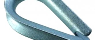
Please note that a stopper is required in such devices. This design is used for small heights or lengths of cargo movement. A cable guide will help increase the movement distance by evenly distributing the cable along the length of the cylinder. The easiest way to get the result is to use a spring-loaded plate or rod that presses the cable to the drum:
Purpose of the device
When driving off-road, a driver may encounter an insurmountable obstacle. Then the car will have to be pulled out of the mud or sand with something. A winch is the ideal tool for this. Some vehicles have the device installed on the front bumper from the factory. Purchasing a ready-made winch can cost a lot of money, so it makes sense to make it yourself using improvised materials.
A factory or homemade winch with a manual drive (or with an electric drive from a starter) allows you to pull out a car without a tow. Experienced car enthusiasts prefer home-made devices that fully meet their needs. Factory winches often fail or cost a lot of money.
There are different types of structures. It is impossible to say unequivocally which one is better. Different types are used for different situations and purposes.
Device types
Classification is the first thing you need to know about the traction device. They are divided depending on the type of design, drive and technical features. Some types of winches are easy to make yourself - this is the simplest mechanism with a manual drive .
And complex structures will work reliably only if they are manufactured in a factory. This specificity must be taken into account when choosing a type for self-production. There are removable and stationary winches. The first option can be removed from the car, carried out maintenance or used for other economic purposes.
Classification depending on the type of drive:
- Manual. Its advantages are its small size and relatively light weight. The work is carried out according to the drum principle. The cable is pulled onto a separate reel, and it is rotated by hand. The disadvantage lies in the limitation of the mass with which work can be done - no more than 1 ton.
- Mechanical. The drum with the cable is rotated by the machine's engine. The design is heavy, so car enthusiasts rarely use it.
- Electric. The best option is for the drum to be driven by an electric motor. The latter is powered by a battery or the vehicle's electrical system. The load capacity in this version is 4 tons.
- Hydraulic. The design is complex, but it works silently and with great traction force. But such systems are unreliable and expensive. Another drawback is that it is impossible to make a hydraulic drive system yourself.
The manual winch is ideal for DIY. The system has a simple design that can be easily made from available materials. There are no complicated moving parts. You just need to decide on the parameters. If desired, you can install an electric motor on such a device, which will eliminate physical labor.
Safety precautions when installing a winch
We advise you to carefully study the installation method of each model personally and strictly follow the manufacturer’s requirements.
- When installing the winch, it is necessary to wear leather gloves and special clothing, excluding long hair from getting on the device.
- Use safety glasses and masks.
- When winding the cable onto the drum, beware of knots.
- Excessive pulling on wires is not recommended.
- Install the winch so that it does not interfere with the operation of the vehicle’s standard systems.
- Leave space between the winch and parts of the car.
A simple option made from scrap materials
Some motorists often drive into a field or forest, which may result in problems negotiating difficult areas - mud and sand.
The car gets stuck, and you have to puzzle over how to get it out. The simplest hand-made homemade winch can be made in the field. Materials:
- Scrap and pipe cuttings.
- Cable.
- A piece of pipe for a lever.
It is unlikely that you will have the materials with you on the road. But everything you need can be found in the nearest village. Instead of a cable, a strong rope will do.
Manufacturing procedure:
- Drive a crowbar or a small diameter tube into the ground to create an axle.
- A larger diameter tube is placed on the axle, to which a cable is attached.
- A lever is slipped under the lower turn of the cable. This could be another tube, a shovel handle, or a pole. The main thing is that the material is durable.
With such a device, which can be assembled in ten minutes, you can move any heavy object, not just a car. The lever is rotated so that the cable is wound around the pipe. Such a manual winch will help to quickly solve the problems of moving heavy loads. This is not a full-fledged device, but it will get the job done.
Manufacturing a system with a universal drive
The manual system is easy to manufacture. Of the special skills the master is required to do, only own a welding machine. Any metal will do the job. The appearance of the device is not so important, the main thing is performance and resistance to heavy loads. The frame should not be deformed.
Materials and tools:
- Rectangular tube for frame.
- Shaft for the drum, you can use a round tube.
- A sheet of metal with a thickness of at least 3 mm for the manufacture of drum disks.
- Threaded rods M10-M12, 24 cm long – 6 pieces, nuts.
- Tube diameter 14 mm - 6 identical pieces of 20 cm.
- Asterisks - large and small. Chain.
- Hubs to secure the drum to the shaft and secure the shaft to the frame.
- Drive lever.
- Cable with carabiner.
- Welding and electrodes.
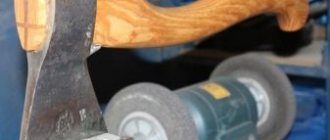
- Grinder and grinding disc for it.
- Paint and primer.
- Wrenches included in the set.
Some materials are better purchased - for example, tubes for the studs and shaft. The rest can be picked up from old mechanisms - cars or motorcycles. Any metal will do, even used.
Manufacturing procedure:
- They sketch out a drawing, because this will make it easier to navigate during assembly - you won’t have to stand guessing over the half-finished product and think about what to do next.
- Cut out the frame parts from a pipe with a cross-section of 2 by 2 cm. Connect the frame parts together strictly perpendicularly. The cut on the workpieces is made at an angle of 45 degrees.
- Lay the frame blanks on a flat surface. The joints are spot-tightened by welding, after which they check whether everything is installed correctly. The angles of the connections must be strictly 90 degrees. If there is a lack of accuracy, corrections are made and then the parts are welded.
- Scale is removed with a grinder and a grinding wheel. The finished frame is sanded and then coated with a primer. After the latter has dried, the metal is painted with enamel in 2 layers. You can use regular paint. The goal is to protect the metal from corrosion, since operating conditions will be difficult, with dirt and moisture.
- Creating a drum. Take a sheet of metal and cut out 2 circles, their diameter is about 30 cm. On each circle you need to make 7 holes:
- One in the center. The diameter must match the shaft size.
- 6 holes at a distance of 7 cm.
- The discs are fastened together using pins. The pin is inserted into the hole of one disk in a vertical position. Tubes with a diameter of 14 cm are put on the studs, and a second disk is installed on them. The studs must not only be secured with nuts, but also additionally reinforced with locknuts to ensure reliable connections.
- The drum is ready, now the shaft is mounted. It is made from a metal pipe, but you can take a finished product from any mechanism. The latter option is preferable: since the accuracy of the factory part is higher, vibrations of the drum will be small or absent altogether.
- A large diameter sprocket is mounted on the shaft on the outside of the drum. A sprocket from a motorcycle gearbox will do. To secure the drum to the frame, the outer sides of the shaft must have hubs.
- The drum assembly with the shaft is mounted through the hubs on the frame. The structure is secured with bolts. Before installing the drum, you should prepare a platform on the frame. A drive will be installed on it - manual or electric. When using an electric drive, a motor is placed on the platform with a small sprocket attached to its shaft.
- A universal drive is often installed: a handle is placed on the reverse side of the output shaft of the electric motor. In the absence of electricity, the winch can be turned manually.
- It is important to properly tension the chain. It should not sag, but strong tension is also unacceptable - this will cause the sprockets to wear out faster, and the chain may break. Check the chain tension by rotating the drum - the chain should not hinder its rotation when the cable is unwound.
- The end of the cable is secured to the shaft and wound around the drum. A carabiner is hung on the other, free end of the cable.
- A shank is attached to one end of the frame. With its help, the winch is secured to the car frame.
Preparing for installation
So, first, let's discuss the stationary installation of electronic auto winches, because they are the most popular among jeepers. Electronic winches are usually installed on the front bumper of a jeep. It can also be installed on the rear bumper, also on both sides, if this does not contradict the requirements of the State Traffic Safety Inspectorate (State Road Traffic Safety Inspectorate - an agency of the Ministry of Internal Affairs of Russia, which carries out special control, supervisory and licensing functions in the field of road safety)
, but we’ll talk about this a little later. First, let's tell you how to install a winch on a standard bumper.
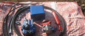
Auto winches are installed on special iron platforms or on a bumper, on which there is space for mounting the winch. Almost all winch models have mounting platforms included with the winch. The kit also includes a roller cable guide, cable, hook, bolts of suitable sizes and a device passport.
1. First, the bumper is removed, and the iron platform is installed on the frame on tacks using bolts.
The space in which the platform is installed must be strong, reliable and capable of withstanding a load no less than the maximum lifting capacity of the winch.
The platform must be fastened on 4 sides, therefore, if the holes do not match, additional holes must be drilled. After installing the platform, it is worth trying on the bumper, because the dimensions of the platform may not coincide with the dimensions and features of the bumper; in this case, it is necessary to cut off the protruding parts of the platform with a grinder.
2. After installing the platform, it is necessary to mount a cable guide on it, through which the cable with the hook will come out. If there is no room on the bumper for the hook to be pulled out, you will need to cut the window to a suitable size.
3. Next, a winch is installed, which is attached to the iron platform using the bolts included in the kit.
4. When the winch is mounted, it is time to connect the electronic control unit and wind the cable. It is recommended to install the electronic unit near the battery, away from dirt and water. If the space inside the bumper makes it possible, then the unit is installed specifically on the winch. Next, the positive cable of the winch is connected to the positive terminal, and the negative cable to the negative terminal of the battery.
5. Almost all models of electronic winches operate using a wired control panel. After mounting and connection, the cable begins to wind, which is connected to the hook and installed on the winch before connecting the electronic unit. It is recommended to wind the cable slowly onto the drum to avoid uneven winding and the risk of the cable touching parts of the car.
Winches are complex devices, the installation and connection of which must be carried out by qualified specialists in special service centers. Incorrect installation of the winch can lead to damage to the device, vehicle, and also harm surrounding people and objects.
Assembly Tips
Design development is carried out carefully, as well as assembly. The task is to treat each operation as responsibly as possible. The goal is to complete the assembly with high quality. This will avoid troubles when operating in extreme conditions. Therefore, there is no need to force the work, even if it is really necessary.
Steps to achieve high build quality:
- The work is done slowly and thoughtfully. A raw, unfinished unit cannot be used.
- Follow the drawing.
- Weld seams are treated with an anti-corrosion compound. Welding is done in carbon dioxide to obtain a high-quality seam.
- The electric drive control panel is placed as far away from rotating parts as possible.
- Electrical wiring is carefully insulated. The contacts are protected by additional insulation from moisture and dirt.
Negative results often arise due to hasty actions. The issue of moving cargo in a horizontal plane with its own device will be successfully resolved. To lift loads above the ground, the cable must be pulled over a strong support.
DIY mini-crane: overview of options
When building a house from aerated concrete, timber, brick, etc. There is often a need to lift a load. For example, you need to “throw” blocks or wooden beams onto the second floor, lift bags of cement, or pour an armored belt. Doing this manually, even with the help of assistants, is not so easy - health is more expensive. Hiring a truck crane or manipulator for a small amount of work is expensive. The solution is to use a mini-crane, which, to reduce the cost of construction, is made by hand.
- How to make a lift for laying aerated concrete.
- What parts and tools are needed to build a mini crane.
- How to reduce the costs of building a universal lift.
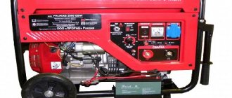
Technical properties
- Voltage, V - 220±10%
- Frequency, Hz (unit of frequency of periodic processes in the International System of Units SI)
– 50 - Power consumption – (1,500 – 2,200) W
- Traction force, kg – up to 500
- Travel speed of trailed tool, m/min – 45÷60
- Dimensions (L×W×H), mm – 680 x 410 x 460
- Length of power cord with plug, at least, m – 1
- Weight, kg – 37
- Cable length, m – 30
Interesting read: Replacing the electricity meter in an apartment with your own hands
Lift for laying aerated concrete blocks
Abroad, during the construction of private houses, cranes and various lifts are often used. This way construction goes faster, which means the “box” is cheaper, because It is more profitable to use small-scale mechanization tools than to hire laborers. Our developer relies on himself and often builds a house “with one helmet.” Therefore, the urgent question is how not to physically overstrain yourself when laying a wall from aerated concrete blocks weighing 35-40 kg.
An interesting option is the unusual homemade “assistant” of the FORUMHOUSE user with the nickname Krestik. First, let's show what he took as a basis.
German mini crane with retractable central post
A special feature of the lift is the original folding “arm-boom”, with the help of which the crane, moving on wheels, can reach two opposite walls.
I am building a house myself and, in order to be able to lay aerated concrete blocks, I built a lift according to the above model. The crane was made completely collapsible, except for the base. I didn’t measure the maximum load on the hook, but it easily lifts me (weighing 95 kg).
Technical characteristics of the lift:
- width – 2200 mm;
- height – 4200 mm;
- boom radius – 4200 mm;
- load capacity of electric hoist – up to 800 kg;
- total weight of the crane with ballast is approximately 650 kg;
- lift weight without ballast – about 300 kg;
- The maximum lifting height of the masonry block is 3500 mm.
The working height of lifting blocks is adjustable in two ranges. The first is 1750 mm. The second is 3.5 m, for which the structure is raised, sliding upward along the supporting “legs” using a hydraulic jack lined with spacers made of GB blocks.
To make the lift, the user needed:
- swivel wheels;
- profile pipes for the mast, “legs” and boom with a section of 12x12 cm, 12x6 cm, wall 6 mm;
- pipe-jibs – 63x3 mm;
- powerful gate hinges;
- The boom rotating mechanism is made of ST45 steel and “205” bearings.
During operation, the design was modified. For example, the user laid the cable for the winch in a corrugated pipe and extended the cable for the control panel.
The design has a number of shortcomings that I would like to correct. For example, I’m thinking about making wireless control, replacing the gate hinges with bearings. Increase the number of “joints” in the boom at the same reach. Instead of a temporary counterweight - bags of sand concrete, pour concrete ballast.
Important nuance : in order for the lift to move around a construction site or, for example, on a concrete floor slab on the second floor, you need to keep the workplace clean, because GB fragments and debris interfere with the relocation of the tap.
Payment (issue of money for any obligation) and delivery
Payment (issue of money for some obligation)
by bank card via online payment:
- After agreeing on the order with the sales manager, you will be sent a link to pay for the order.
- By clicking on the link, you can pay for your order using a Visa, Mastercard or MIR payment card
- After successful payment you will receive an electric receipt
- The information indicated on the receipt contains all the data about the payment transaction performed.
- Your payment card data is guaranteed to be protected in accordance with PCI DSS security standards.
- Card details are entered on a secure bank payment page; information is transferred using SSL encryption technology.
- The upcoming transfer of information takes place through closed banking networks that have the highest level of reliability.
- For additional authentication of the Cardholder, the 3D-Secure protocol is used.
- If the Issuer supports this technology, you will be redirected to its server to enter additional payment details
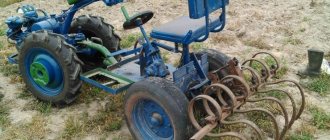
I’m using the 2nd season, I like everything, it’s more convenient than the others. I tried various gasoline and electronic ones, I saw them at my neighbor’s and decided to try them, I didn’t regret it. Although the speed is the same, it is quite successfully selected; I also used it for dragging building materials; it is quite powerful; it drags rounded logs easily. Thanks to the manufacturer!
Alexander
I can say with confidence that the Boomerang is better than the Belarusian winch. stronger, lighter, higher speed, excellent plowing ability, even furrows. My companion has a Mogilev one. He was unable to plow two-year-old alfalfa due to lack of power. I helped him on my own - the crackling of roots could be heard throughout the entire area. I can plow alone, he can’t even plow sand alone. The cost of "Boomerang" is more expensive, but it is worth the money.
Alina Galieva
I recently bought this winch. Delivery can be said to be instant 3 days to Kursk. I also got a plow and a hiller. The first time I examined this product very meticulously with the feeling that I had overpaid. What can we say - made to last. Well, it’s one thing to look at it, and another to check it in action. Therefore, we decided to test it while plowing a semi-abandoned plot at our parents’ dacha. There was such a malicious grin on my father’s face - his walk-behind tractor weighs 90 kg. A plot of 2.7 acres, half overgrown with grass three years ago, the other half was cultivated in the autumn. They mowed the grass and began to cultivate the area with a walk-behind tractor - after 40 minutes the result was virtually zero because the cuts were clogged with grass, and the ground was not easy and was quite wet. We decided to test this winch with a plow - not everything worked out right away, but in 2.5 hours we plowed the entire area and the engine still didn’t heat up at all. Honestly impressed. Therefore, I can confidently recommend this accessory.
Maxim Lunev
Mini crane made from scrap metal
Another version of a lifting mechanism made of metal “lying underfoot” was made by a portal participant with the nickname Petr_1.
According to Peter_1, the reason for the construction of the crane is that the house is getting higher and higher, and the blocks and concrete are getting heavier. Therefore, after revising the “unnecessary things”, the user manufactured a completely dismountable crane with a lifting capacity of 200 kg.
I think my crane can lift more, but I didn’t overload it. The crane can be disassembled into parts weighing 30-60 kg and can be easily transported in a car trailer. I carry an arrow on the trunk. Statically tested a structure weighing 400 kg. I usually lift up to 150 kg. This is quite enough for my construction needs.
The design of the crane is a hodgepodge of what was at hand. Let's list the main details:
- swivel unit - truck hub;
- the boom is made of a pipe with a diameter of 75 mm;
- outriggers and base - a rectangular pipe with a section of 8x5 and 8.5x5.5 cm;
- the base of the tower is the “200th” channel;
- worm gearboxes for boom and cargo winches.
- three-phase electric motor with reverse, power 0.9 kW, converted to power from a 220 V network;
The crane turned out to be mobile, and by lowering the boom, it can be moved from place to place, rolling on wheels along compacted soil. Level adjustment is carried out using screw supports.
Metal, gearboxes and rollers were purchased at a recycled metal shop. Only the cable and bearings are new.
The weight of the crane without counterweight is about 250 kg. The cost of the structure, taking into account the purchase of consumables - cutting discs for angle grinders, electrodes for a welding inverter and paint, is 4 thousand rubles.
Crane, + time for turning, + selection of components and fitting of components, I completed it in 3 working days. In the future, after finishing the work, I will completely disassemble it.
Winch functions
The electronic winch “Boomerang” is designed for cultivating land using a trailed tool: an arable plow and/or hiller, a potato digger. Suitable for any type of land: it processes virgin soil and clay, where walk-behind tractors from renowned manufacturers are sometimes not controlled.
The winch can also be used to transport over short distances (taking into account the length of the cable) sleds, drags and other similar devices with a total weight of up to 500 kg by dragging.
We have made the electronic winch very comfortable to use. It is small in size, so it can easily fit into the trunk of a car. It is easy to assemble and maintain, and even a child can operate the winch. Such a tool is suitable for any owner of a suburban plot. It will last you up to 10 years and even more!
Still in doubt? See with your own eyes how the winch works and make sure of its reliability:
Inexpensive mini lift
Practice shows that when building a private house, a real crane is not always needed. Often, a developer can get by with “little expense” and make a small lift based on an electrically driven hoist.
My design is simpler than the authors above, but it suits me quite well. I bought a hoist with a load capacity of 300 kg without a block and 600 kg with a block. Tests have shown that the device can lift a load weighing 250-270 kg, then the engine protection is triggered. During the construction season, I used it to lift about 40 pallets with building blocks, a 6-meter beam for the mauerlat, rafters, mortar for masonry and concrete for the reinforced belt.
The lift, again to save money, is made from used pipes, angles and channels.
All rust was cleaned off with a grinder, and the pipes were sprayed and then painted with paint with a rust reducer.
In order to be able to assemble the lift on the ceiling of the second floor, all components (where welding is not needed) are made dismountable - with bolted connections.
A hoist is installed on the stand using clamps.
In case of rain, a plastic bottle with the bottom cut off is placed on the control panel.
The telpher covers a canopy made of used roofing iron.
When lifting a pallet, two boards are placed under it, and the pallet is lowered onto them.
The entire structure is fixed to the floor with clamps.
Drawing with dimensions of the lift.
These are topics that describe in detail how to make a lift for aerated concrete, and provide dozens of options for mini-cranes, from simple to the most complex designs.