To process parts and workpieces with shaped and flat surfaces, gears, milling machines are used. They are widely used in the industrial and metalworking fields. Despite the variety of types, the main elements of the device are similar. In all machines, the main movement is the movement of the cutter. And the feed movement is made relative to the movement of the workpiece and the cutter.
All capabilities of the milling machine are expanded with these add-ons:
- universal, slotting or vertical head;
- round dividing table;
- universal dividing apparatus;
- device for cutting combs.
Now let's take a closer look at a certain type of milling machines.
Vertical milling machines
This unit is designed for processing workpieces using face, shaped and cylindrical end mills. It is also possible to perform drilling work . Serves for processing gear wheels, frames and corners, vertical and horizontal planes, which are made of steel, cast iron, as well as non-ferrous and various alloys.
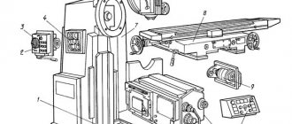
In such machines there is no console, and the table moves along the guides of the bed. Thanks to this design, it has extreme rigidity, which, in turn, ensures relatively accurate processing of the part. The spindle head is also a gearbox. The spindle together with the sleeve can be moved in the axial direction.
The vertical milling machine has two types:
- vertical console-milling;
- vertical without console.
Main technical characteristics
The main difference between milling operations and the equipment intended for this is the number of coordinates in which the surface is simultaneously processed. The following parameters are used to describe the technological properties of milling machines:
- accuracy of operations;
- maximum movements along coordinates;
- feed modes and speeds;
- cutting and loading modes;
- availability of mechanized tool change;
- possibility of installing additional equipment;
- power consumption.
Each of these characteristics affects the overall design of the machine. The final parameters combine a compromise between the main characteristics.
Horizontal milling devices
This type is used for processing parts of small diameters, and it has a horizontal spindle. This design allows the processing of screw, shaped, as well as horizontal and vertical surfaces, corners and grooves. The work is carried out using cylindrical and disk, end, corner, end, and shaped cutters. Processing of a workpiece that requires a screw movement or division is permissible when using additional devices.
The feature that distinguishes it is the ability to move the table perpendicularly and parallel to the spindle axis . All important components are placed on the frame, inside of which there is a gearbox and a spindle assembly. The feed box is located on the console, and the console moves along vertical guides. The trunk with earrings serves to support the tool holder.
Features of the process and cutting modes during milling
Features of the milling process are the intermittent nature of the cutting process with each tooth of the cutter and the variability of the thickness of the cut layer. Each cutter tooth is involved in cutting only for a certain part of the cutter revolution; the rest of the cutter passes through the air, idle, which ensures cooling of the tooth and crushing of chips.
In cylindrical milling of planes, the cutting work is carried out by teeth located on the cylindrical surface of the cutter. When face milling planes, the cutting work is carried out by teeth located on the cylindrical and end surfaces of the cutter. Cutting modes during milling include cutting speed, feed (minute, per revolution and per tooth), depth of cut and milling width B. Cutting speed, mm/min, is calculated as the peripheral rotation speed of the cutter:
V = πDфn/1 000,
where Df is the outer diameter of the cutter, mm; n – machine spindle rotation speed, mm/rev.
Dependencies between feeds: minute Sm, per revolution So and per tooth Sz:
Sм= Son = Sznz = S2x,
where z is the number of tool teeth.
The influence of cutter diameter on machining performance is ambiguous. As the cutter diameter increases, the design cutting speed increases with constant tool life; this is explained by the fact that the average thickness of the cut layer decreases, the cooling conditions for the cutter tooth improve, since the time the tooth spends outside the cutting zone increases.
In order to increase productivity, it is better to choose cutters with a larger diameter, since with an increase in cutting speed, the cutter rotation speed and minute feed increase proportionally (with a proportional increase in the number of cutter teeth). The possibilities of increasing the diameter of cutters are limited by the power and rigidity of the machine, and the size of the tool hole in the machine spindle.
Drilling units
Metalworking machines, which belong to the group of drilling and milling machines, are used for processing horizontal, vertical and inclined surfaces. It is also possible to make grooves in large-sized parts using them.
This type of metal machine has a drilling and milling head, which allows drilling at an angle and processing a surface located at an angle to the horizontal axis. The fact that the working head can operate in reverse mode is its difference, versatility, a certain probability of carrying out two or more popular operations, these machines are very profitable in terms of cost savings and space saving on the production area. No home craftsman would refuse to have such a device at home, because it combines several effective and useful devices.
Types of cutters, their elements and geometry
A milling cutter is a multi-bladed tool with cutting teeth located around its circumference or at the end, which are the simplest cutters. In Fig. Figure 28 shows the main types of cutters used in mechanical engineering.
Milling cutters are divided into types: cylindrical (Fig. 28, a, b) and end (Fig. 28, f), intended for processing flat surfaces; disk (Fig. 28, c–e), end (Fig. 28, g) and angular - for processing grooves, grooves and splines; shaped – for processing shaped surfaces; modular (Fig. 28, h) - for cutting teeth; worm (Fig. 28, i) - for cutting teeth of cylindrical and worm wheels.
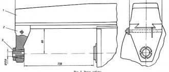
Tooth 4 of a cylindrical cutter (Fig. 28, a) has a cutting edge 2; anterior 1, posterior 3 and occipital 5 surfaces. There is a groove 6 between the cutter teeth. In the cutter section, the following angles are considered: front γ, rear α, sharpening β and cutting δ.
The rake angle γ serves to facilitate the flow of cut chip elements and reduce their shrinkage.
When processing steel γ = 10–20°, cast iron – γ = 10–15°. For hard materials, the angle γ is taken smaller than for soft ones.
The clearance angle α is chosen in such a way as to reduce friction between the back surface of the tooth and the cutting surface. For various cutters, the angle α = 12–25°.
The teeth of cylindrical cutters can be straight or helical at an angle of inclination ω to the cutter axis (see Fig. 28, b). For cylindrical cutters the angle is ω = 30–40°, for disk and face cutters it is ω = 10–25°.
The cutter is made in one piece from tool steels and in prefabricated ones, in which the teeth are made of high-speed steels or equipped with plates made of hard alloys and secured in the cutter body by soldering or mechanically (GOST R 53413–2009).
Rice. 28. Main types of cutters : a – cylindrical spur, where 1, 3, 5 are the front, back and occipital surfaces, respectively; 2 – cutting edge; 4 – tooth; 6 – groove; α – clearance angle; β – sharpening angle; γ – front angle; δ – cutting angle; ω – angle of inclination of the teeth to the cutter axis; b – cylindrical with helical teeth; c – disk groove; g – double-sided disk; d – three-sided disk; e – end; g – end; h – finger modular; and – worm
A cutter with straight teeth cuts into the surface being machined along the entire length of the tooth, which leads to a variable (impetuous) load on the machine and some deterioration in the quality of the machined surface. Cutters with helical teeth work more smoothly, since the cutter teeth cut into the part gradually, while the machine is loaded more evenly.
Universal milling
In small-scale production, this type is used to produce parts by milling. In small mechanical repair shops, as well as in tool shops.
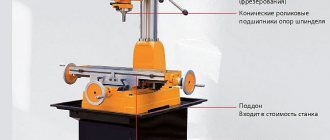
Together with the main components, the spindle assembly and gearbox are located inside the frame. The console moves along vertical guides , and along the cantilever guides move a slide with a rotating mechanism, on which a special table is placed, which moves in a horizontal plane at various angles relative to the spindle axis. With the help of design features, the work performed on such machines is done efficiently and quickly.
Operating rules
When working on a horizontal milling machine, you must comply with the safety regulations and regulations. Machine operators neglect these rules, and this poses a great danger to others and the performance of the equipment.
In order for the machine to serve for a long time and properly, you need to study its maximum characteristics. In no case should they be exceeded, as this can lead not only to damage to the equipment, but also to injury to the operator. A broken tool due to violation of cutting conditions can cripple the person working on it. It is prohibited to work on the machine without personal protective equipment and protective screens.
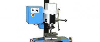
Tabletop machines
Tabletop ones are very compact and thanks to this they are widely popular in equipment repair shops, auto repair shops, and such machines are also installed in schools and vocational schools. With their help the following works are carried out:
- drilling holes, cutting threads, vertical milling with end, face and key cutters;
- horizontal milling with cylindrical, disk and other cutters is also carried out with their help.
The design feature of such machines is their rigidity when installed correctly . If it is installed correctly, then all work will be completed relatively accurately. This type is used in the mass production of various parts. Low energy consumption, their compactness, maneuverability and low cost are the advantages of such machines.
Milling horizontal and vertical planes
Milling planes is the most typical operational work performed when processing most parts on milling machines.
In this case, it is necessary to solve a number of typical problems that are also typical for other milling operations, such as, for example, milling shoulders, grooves, grooves, etc. In this regard, it becomes advisable to systematize the actions of the miller, which can be expressed in the form of a logical diagram (Fig. 40). At the 1st stage of such a scheme, the initial data that determines the technical requirements is studied
requirements for the upcoming work and the conditions for its implementation. For a specific practical work, this data consists of a working drawing, a workpiece and the technical capabilities of the machine.
When studying the drawing, you should determine the requirements for the accuracy of surface treatment and the material of the part. Machining accuracy, as is already known, includes four elements: dimensional accuracy, accuracy of the geometric shape of the surface, accuracy of its location to other surfaces of the part, and surface roughness.
When considering workpieces, it is necessary to determine their type, size, adequacy of allowance for surface treatment, and the absence of significant distortion and curvature.
The technical capabilities of the machine are characterized by its type, size, spindle speeds, minute feeds, the presence and condition of a compensating device for selecting backlash in the longitudinal table feed mechanism, and power.
At the 2nd stage, theoretical preparation for work is carried out
. Here, based on the analysis of the initial data, the following are selected: means for measuring and monitoring the accuracy of surface treatment; method of installing the workpiece on the machine and type of clamping device; method and method of surface treatment; type, material and dimensions of the cutter: cutting and cooling mode.
At the 3rd stage, practical preparation of the machine for operation is carried out
(its setup and adjustment), which includes: installation, alignment and securing of the fixture and workpiece on the machine; installation and fastening of a cutter on the machine; position of the workpiece relative to the cutter; setting the machine for rotation speed, minute feed, direction of spindle rotation and cooling mode.
At the 4th stage, techniques directly related to the performance of work are carried out
, namely: setting the workpiece to the cutting depth; machine control; control of surface processing accuracy.
Below, only the actions of the milling operator related to the 4th stage of the logical diagram are considered, since methods for solving other problems at the remaining stages were described earlier.
Setting the workpiece to the cutting depth when processing horizontal planes is carried out as follows. Using the handwheels for manual table movements, bring the workpiece under the rotating cutter until it touches lightly, which will be indicated by the appearance of a slightly noticeable mark of the cutter teeth on its surface. This position of the workpiece is the beginning for counting the cutting depth along the vertical feed dial of the table.
To make it easier to count, the dial ring is set to zero, i.e., its zero mark is combined with a fixed index mark. After this, by longitudinally moving the table in the opposite direction of the working feed, the workpiece is removed from under the cutter and the table is raised to the required cutting depth. The number of dial divisions is determined as the ratio of the cutting depth to the cost of one dial division.
At the cost of dividing the dial
the amount of movement of the machine table is called, corresponding to the rotation of the dial by one division. For example, if, when raising the table by 2 mm, the dial was rotated by 40 divisions, then the price of one division will be equal to 2:40 = 0.05 mm. If the cutting depth is 3 mm, at the same cost of one dial division it must be rotated by 3:0.05 = 60 divisions.
If the workpiece has a previously machined lower surface, then when setting the cutting depth it is necessary to maintain the required size between the opposite surfaces of the part. In this case, first set the cutting depth, slightly less than the required one, and perform test milling to a length of 3...5 mm. After measuring the actual size, the machine table is adjusted vertically until the required part size is obtained on the dial, then the dial ring is set to zero in order to process all subsequent parts from the batch without trial readings.
When using dials, it is necessary to take into account the presence and magnitude of play (gap) in the screws neper allowing the table to move. If, for example, the raised table is lowered, then with some rotation of the vertical feed lever the table will remain in place (this characterizes the amount of play in the transmission). Therefore, when measuring dimensions using machine dials, the handwheels or manual feed lever should be turned only in one direction (Fig. 41). If a mistake is made and the dial is turned by a greater number of divisions than required, then the handwheel (lever) is turned in the opposite direction by an amount slightly greater than the amount of play (about 0.5...1 turn), and then, rotating in the same direction, the dial is adjusted to the desired division. The same is done when you need to move the workpiece away from the cutter to a certain size. To do this, first select the backlash and move the table a little more than required, and then, feeding the workpiece to the cutter, bring the dial to the desired division.
When milling a vertical plane with an end mill on a horizontal milling machine (Fig. 42), the cutting depth is set in the same way as described above, but in this case the table’s transverse feed dial is used.
Machine control and processing accuracy control. When the cutting depth is set, the moving parts of the machine, the movement of which is not used when performing this work, should be fixed to increase overall rigidity. When milling horizontal planes, the slide is clamped, and when milling vertical planes, the console is clamped. After this, by manually moving the table, the workpiece is smoothly brought to the rotating cutter, cut into the metal and the mechanical feed is turned on. At the end of milling, when the workpiece comes out from under the cutter by 2...4 mm, the machine is stopped, the table is lowered slightly and the treated surface is cleaned of chips with a brush . Then the table is returned to its original position using rapid feed.
When processing parts in batches, it is advisable to automate the switching off of mechanical table feeds using limit cams. The cams are positioned and secured in the table groove so that the feed is turned off at the end of milling and in the initial position of the table.
The burrs around the perimeter of the machined surface are removed with a file from the workpiece removed from the machine. After this, it is subjected to control for size, accuracy of the geometric shape of the surface (straightness, flatness) and roughness, respectively, using a caliper, a measuring ruler and roughness samples.
Let's consider the sequence of actions of a milling operator when processing a plane using a specific example.
Example
. It is necessary to process a horizontal plane of a prismatic workpiece made of steel 40.
Initial data: part drawing (Fig. 43), blank - rectangular rolled product 45 mm wide, 50 mm high and 80 mm long (abbreviated 45x50x80 mm); machine - horizontal milling model 6R81G.
Solution. Using the logical diagram of actions when performing operational work (see Fig. 40), we first study the initial data - stage 1.
According to the working drawing, the plane being processed must meet the following requirements. Size 47-0.62 should be within the largest limit size of 47 mm and the smallest limit of 46.38 mm; non-flatness is allowed no more than 0.1 mm; surface roughness - no more than Rz40.
The material of the part is steel 40. This is high-quality structural carbon steel containing 0.4% carbon.
The part is not subjected to heat treatment. Therefore, given the low accuracy, it can be finally processed on a milling machine.
A workpiece measuring 50 mm has a sufficient allowance of 3 mm; its curvature is within acceptable limits.
The work is provided on a 1st size cantilever horizontal milling machine, having: spindle speed limits of 50...1600 rpm; limits of longitudinal feeds 35…1020 mm/min; compensating device for selecting backlash in the longitudinal table feed mechanism; electric motor of the main movement with a power of 5.5 kW.
At the 2nd stage of action, we conduct theoretical preparation for work.
1. To measure and control processing accuracy, select; ShTs-1 caliper with a reading accuracy of 0.1 mm, a measuring ruler, probes, roughness samples.
2. We accept the method of installing workpieces on the machine - in a vice. To do this, we use a machine rotary vice with grooved overhead jaws.
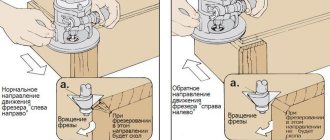
3. The type and technical characteristics of the machine allow you to choose the processing method - a cylindrical cutter and the milling method - downhill.
4. Taking into account the semi-finish nature of the processing, we use a solid cylindrical cutter made of high-speed steel with a large tooth for the work. We take the dimensions of the cutter such that its diameter D is as small as possible, and its length L allows milling along the short side of the workpiece in one pass. From the appendix at the end of the book, select a cutter 0 63 mm and L = 100 mm with the number of teeth z = 8. The direction of the screw teeth is right.
5. Select the cutting mode. Taking into account the small allowance for processing and sufficient rigidity of the workpiece, we will perform milling of the plane in one pass with a milling width of B = 80 mm and a cutting depth of Z = 3 mm. According to the table 1 we accept: feed per tooth sz=0.15 mm/tooth, cutting speed v=30 m/min. The work will be performed using coolant (emulsion).
Determine the required rotation speed of the cutter:
n = 320v/D = 320*30/63 = 152 (rpm).
We take the value closest to the machine as n = 160 rpm. Determine the minute feed;
sм = sz, z * n = 0.15 * 8 * 160 = 182 (mm/min).
According to the machine sm = 170 mm/min.
At the 3rd stage of action, we carry out practical preparation of the machine for operation.
1. Install and align the vice and the workpiece on the machine.
Before installing the vice, clean its supporting surface and the working surface of the table from dirt and chips. We install the vice so that the guide keys fit into the middle groove of the table and are pressed against one of its sides. We insert the mounting bolts into the groove of the table and the eyes of the vice and tighten the nuts one by one with a wrench. We rotate the body of the vice by 90° on a degree scale so that the jaws are positioned perpendicular to the longitudinal feed of the table, and the cutting force from the side of the cutter is directed towards the stationary jaw. Then we install and secure the workpiece in a vice.
To reduce distortion and increase the strength of fastening of workpieces, the sides of which are not processed, it is recommended to place two small metal squares 1 (Fig. 44) of the same thickness on the movable jaw of the vice.
2. Install the cutter on the machine. To do this, according to the size of the cutter mounting hole and the shackle bearing design of the machine used, we select a center milling mandrel with a working part diameter of d=27 mm and a shank with a taper of 7:24.
Guided by the rules set out earlier, we install and secure the centering mandrel on the machine.
Using manual feed, we bring the machine table to the vertical guides of the bed, maintaining a gap of 10...15 mm between them. Based on the workpiece, we place the mounting rings and cutter on the mandrel. In this case, the cutter should be located on the mandrel approximately symmetrically to the workpiece and with such a side that the axial component of the cutting force is directed towards the spindle (see Fig. 32, a). We put the remaining installation rings and the supporting sleeve on the mandrel and first screw on the nut.
We extend the trunk from the frame to the length of the free part of the mandrel and secure it. We put an earring on the end of the trunk and the supporting sleeve of the mandrel and secure it. After this, finally tighten the mandrel nut with a wrench and... We check the runout of the cutter teeth with an indicator.
3. According to the accepted down-milling method, moving the table longitudinally, we position the workpiece on the side of the rear surfaces of the cutter teeth.
4. We set the machine to a spindle speed of 160 rpm, a minute table feed of 170 mm/min, set the spindle to left rotation and connect the motor of the lubricating-cooling system pump.
At the 4th stage of action we perform direct work techniques.
1. Set the cutting depth. To do this, turn on the spindle rotation and manually move the table to bring the workpiece until its upper side lightly touches the cutter. We set the vertical feed dial to zero, move the table longitudinally out from under the cutter, raise the table along the dial by 3 mm and set the dial ring to zero again.
2. We control the machine. To increase its rigidity, we clamp the slide. Using manual longitudinal feed, we cut the cutter into the metal, open the coolant lubricant start-up valve and turn on the mechanical feed. At the end of milling, when the cutter goes beyond the workpiece by 2...4 mm, turn off the machine. We lower the table a little, clean the treated surface from chips with a brush, turn on the rapid feed in the opposite direction and return the table to its original position. After turning off the machine, we release and remove the finished part.
If a batch of parts is to be processed, then when milling the first of them, we configure the machine to work using limiting cams, which allow us to automate the shutdown of the mechanical feed in the extreme working positions of the table.
3. We control the accuracy of processing. We measure size 47-0.62 with a ShTs-1 caliper along the perimeter of the workpiece at at least four corner points. The resulting dimensions must be within the largest limit size - 47 mm and the smallest - 46.38 mm. In this case, special attention should be paid to the absence of distortion of the caliper jaws relative to the controlled surface.
Deviation from flatness is determined by a pattern ruler and a 0.1 mm thick probe based on the clearance between the controlled surface and the measuring edge of the ruler.
The surface roughness is determined visually by comparing the treated surface with roughness samples.
CNC milling machines
These machines have found their application in the mass production of high quality parts. CNC milling machines are much different from ordinary milling machines because they produce equipment using the latest technologies. With their help, you can achieve high quality parts manufacturing at high productivity speed.
In small-scale and mass production, where it is necessary to perform drilling, countersinking, boring holes in parts made of plastic, ferrous and non-ferrous metals, CNC machines are used. This equipment is equipped with a drive that is controlled by a controller connected to any computer.
Among the main advantages note:
- high increase in productivity with a manually operated machine;
- a clear decrease in the need for skilled workers;
- obvious reduction in the transition time to the production of new workpieces;
- more basic and practical equipment;
- high reduction in production cycle time.
Application area
The nature of the application of horizontal milling machines is very diverse. We list the materials that can be processed on them:
- ferrous metals and cast iron;
- non-ferrous and precious metals;
- wood;
- polymer materials, plastic.
According to the type of operations carried out on machines of this type, they are divided into:
- longitudinal milling;
- thicknesser;
- horizontal boring.
Longitudinal milling cutters for metal are used in rough blank operations, making grooves, extended cavities, trimming and cutting operations with disk cutters.
Thicknessers are used in the woodworking industry to calibrate board thickness. They are distinguished by mechanized feeding of the processed material.
Horizontal boring mills are used as part of industrial lines for the production of automotive components, and in repair shops.
The use of rotary tables and USP (universal assembly devices) allows us to expand the scope of application of this type of machines. One of the purposes when installing a workpiece into the dividing head is cutting gear elements.
CNC Machining Centers
In industrial sectors such as automotive, aerospace, instrumentation, and in areas where mass production of high-quality parts is impossible, CNC machining centers are used. With their help, a wide range of milling, boring and drilling work is carried out. Such machines are equipped with modern drives , which are controlled by special controllers connected to any IBM PC. It is worth noting that the monitoring and control system is equipped with high-quality software produced by global manufacturers. A distinctive feature of this machine is its high cutting speed and high accuracy.