corner equipment switches Electrical machine circuit breakers Zhejiang Chinehow Technology Co., Ltd. is a new but outstanding company that is engaged in the research, production and sales of circuit breakers for equipment protection.
Since our establishment in 2004, continuing to develop the concept of independent research and innovation, we have developed several series of products such as CVP-SM, CVP-TH and CVP-FR series until now. We gather many talents in various fields, including electrical appliances to enhance production research capabilities. We have achieved many research results. The major technology index is approaching international levels. Meanwhile, company management and labor efficiency and resource conservation have been improved. Our switches, with their precise tripping, stable performance and high quality, have been accepted by many generator set manufacturers and communication equipment manufacturers.
Our leading products, CVP-SM and CVP-TH and CVP-FR series, have won many national technical monopolies, and we have received ISO9001:2000, CE, TUV, UL, CSA and RoHS certifications. The switches with good performance are applied in industrial automation fields , medical care, communications, data processing, public transport, UPS and signal transmission.
Our switches comply with GB17701-1999, IEC60934:1993 and C22.2 standards. At present, with the dynamic development of science and technology, Chinehow employees adhere to the people-oriented management concept and follow the guideline of technical innovation, combining the concept of innovation, management innovation and technical innovation.
We persistently adhere to the customer-oriented concept to enhance customer satisfaction. With our utmost efforts in long-term innovation, continuous development and continuous improvement, we strive to make the Chinehow brand one of the world's famous brands.
.
Basic indicators
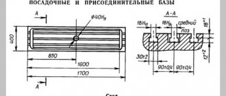
Dimensions of the working plane – 320 x 1250 mm.
The maximum distance from the spindle axis to the working surface is 30 - 410. The maximum distance between the end of the spindle and the supporting bearing is 700 mm. Electric motor power – 7 kW. The rotation speed of the main engine is 1440 rpm, the horizontal spindle is 31.5 ... 1600.
The operating accuracy of the unit is equal to class N.
Table Rotation Options
The working surface can be moved:
- Longitudinal (700mm manually and with mechanics);
- Transversely (260mm by hand and 240mm mechanically);
- Vertically (by 380 mm using both methods).
The maximum rotation angle is set to +/-45 degrees.
The length of the machine 6M82 is 2260mm, width – 1745mm, and height – 1660mm.
The total weight of the installation is 2800 kg.
Limits of machine use in terms of power and power loads
The main limitations for devices with high and medium rotation speeds are related to the maximum speed of the cutting tool and the power of the engine that provides movement.
High cutting speed requires the use of high-speed operating modes. Thus, increased machine productivity and vibration resistance are achieved.
6t12
When a cylindrical high-speed cutting tool is used, feed intensification up to 1500kg is allowed.
Heavy Duty Limits
Heavy duty milling, first of all, requires high strength and stability of the cutter. Experts recommend adhering to the following conditions in such work (Table):
| Index | Face mills for steel | Cylindrical cutters for cast iron | Face milling cutters for cast iron |
| Max cutter diameter (mm) | 150 | 90 | 200 |
| Number of teeth | 14 | 8 | 16 |
| Rotation speed – up to (rpm) | 40 | 50 | 63 |
| Ultimate cutting speed – (m/min) | 19 | 14 | 40 |
| Milling width no more than (mm) | 100 | 109 | 100 |
| Milling depth no more than (mm) | 4-5 | 10-12 | 9 |
| Maximum feed (mm/min) | 160 | 160 | 315 |
| Feed per tooth (mm/min) | 0,28 | 0,4 | 0,31 |
| Power limit (kW) | 6 | 6 | 7 |
The ideal balance in working on this machine:
- Full power + medium speed;
- No more than 75% power + low speed.
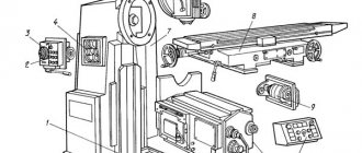
Location of components
The structural base 6K82Sh is a vertical frame mounted on a massive base. All working units and mechanisms are mounted on it. The frame is made in the form of a hollow cast rack. On its right side, in special niches, electrical equipment (below) and a gearbox with a gearbox (above) are located. On the front part of the frame there are two vertical guides, to which a console with a slide is attached, the lower guides of which are connected to the console, and the table is mounted on the upper ones.
A trunk with an additional milling head and seats for earrings is mounted on the upper end of the frame. On the trunk there is an electric motor for the vertical spindle of the head; its movement is carried out manually using a handwheel. To expand the functionality, an overhead milling head can be installed on the rotary head.
Location of controls
6K82Sh has good ergonomics of controls: the main part of the buttons, handwheels and handles are located in front and to the side of the machine operator. On the front plane of the table slide there is a group of buttons: general stop, spindle start and table positioning. Next to them are two steering wheels and a lever for manual positioning in the following directions: longitudinal and transverse and vertical.
Technical characteristics, design and diagrams of the horizontal milling machine model 6р82
Just above the group of buttons on the top surface of the slide there is a longitudinal positioning lever and table clamps, and next to them are the slide clamps. At the left end of the console there is a feed switch handle, and next to it there is a slide locking lever. On the left side of the table there is a backup steering wheel for manual longitudinal positioning.
6A12p Location of components of a cantilever milling machine
Location of components of the 6A12p milling machine
List of components of the 6A12p cantilever milling machine
- feed switch handle;
- cross stroke end cams;
- block of electrical supports “Transverse”;
- block of electrical supports “Vertical”;
- remote control for dialing and reading programs;
- “Return drum to zero position” button;
- Spindle Jog button;
- gear shift handles;
- head rotation screw;
- quill clamp handle;
- quill movement handle;
- end cams of longitudinal stroke;
- block of electric supports “Longitudinal”;
- Remote Control;
- dial for transverse movement of the table;
- dial for vertical movement of the table;
- dial for longitudinal movement of the table;
- slide wedge adjustment screw;
- slide clamp handle.
List of controls
The following components of the machine are no less important than the previous ones:
Gearbox or gearbox
The equipment has a total of 18 gear indicators. This is a separate unit. Usually located on the console, on the left side. The gear shift device is located directly on the console. The front part is equipped with a so-called dial - it is used to apply certain gear indicators to the surface. Marks allow you to easily set feed rates for the working surface, in horizontal or vertical planes.
Swivel head
It looks like a spindle that is positioned vertically. Supplied with an additional roller for receiving. The spindle moves along the axis using a special flywheel, the latter is placed inside a special sleeve. The handle is located inside the left side of the sleeve. This makes it easy to clamp if necessary.
Gearbox
A total of 18 numbers are used on which the spindle rotates. Installed inside the frame body. The shafts of this box are mounted on ball bearings. The plunger pump that regulates lubrication is located on one of these parts.
Sled with work table
The slide is clamped to the console using eccentric clamps. The movement begins from a screw located transversely. At the next stage, everything moves to guides in the shape of a rectangle, console type.
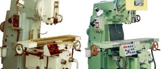
Vertical milling machines
The table also moves using the guides mentioned earlier. He is the final component of the serve chain, which respects the longitudinal position. The rotating screw is responsible for the implementation of such a scheme. The claw clutch handle must be turned on for movement to begin.
The table can be configured in three modes: pendulum, automatic and semi-automatic.
The pendulum mode is controlled using cams. The parts are mounted on the side surface of the table, located in front. If a blockage occurs at the longitudinal stroke lever, the pendulum operating mode cannot be stopped, this leads to damage to the unit.
Kinematic diagram
The kinematic diagram shows that the drive is connected to the electric motor through a coupling. It is responsible for transmitting movement to the structural unit. The transformations of the three blocks determine the number of spindle revolutions. Communication up to 13 speeds is possible, without the need to change in stages.
An electric motor located in the console acts as a gear drive. This happens by one of 18 different feeds through the jaw coupling to the screws. Those, in turn, on a horizontal mill can be of three types: vertical, longitudinal and transverse.
The function of the travel friction is important, which carries out movements through the gears before the feeds. This part is connected to the coupling, simultaneous functionality is limited. The frame is fixed with pins according to the scheme, fixed in a rigid way.
Vertical cantilever milling machine 6T12
Return to: Milling machines Working surface dimensions: 320 x 1250 mm Description
The vertical cantilever milling machine 6T12 is designed for milling all kinds of parts from various materials. It is used in single and serial production.
The 6T12 machine can process vertical and horizontal planes, grooves, corners, frames, gears, etc. The machine can operate in three modes: emergency, jog and manual. In automatic mode, the machine operates in various automatic cycles, including the frame cycle.
In jog mode, adjustment movements of the table are made. Marking work is possible. In the manual universal mode, the 6T12 machine operates using working feeds, rapid movements, as well as manual movements from the flywheels and handle.
Find out about the price, condition and terms of purchase of this cantilever milling machine by sending a request “by product” at the top of the page. Or just call! They will answer you about all available used milling machines.
Technical characteristics of the cantilever milling machine 6T12:
Parameter name 6T12
| Basic machine parameters | |
| Table surface dimensions, mm | 1250 x 320 |
| Maximum mass of the workpiece, kg | 400 |
| Maximum longitudinal stroke of the table (X), mm | 800 |
| Maximum transverse travel of the table (Y), mm | 320 |
| Maximum vertical travel of the table (Z), mm | 420 |
| Spindle | |
| Main drive drive power, kW | 7,5 |
| Spindle speed, rpm | 31,5..1600 |
| Number of spindle speeds | 18 |
| Spindle quill movement, mm | 70 |
| Movement of the spindle quill by one dial division, mm | 0,05 |
| Desktop. Submissions | |
| Limits of longitudinal and transverse table feeds (X, Y), mm/min | 12,5..1600 |
| Limits of vertical table feeds (Z), mm/min | 4,1..530 |
| Number of table feeds (longitudinal, transverse, vertical) | 22 |
| Speed of fast movements (longitudinal, transverse/vertical) X, Y/ Z, m/min | 4/ 1,330 |
| Machine mechanics | |
| Feed stops (longitudinal, transverse, vertical) | Eat |
| Blocking manual and mechanical feeds (longitudinal, transverse, vertical) | Eat |
| Blocking separate feed switching | Eat |
| Electrical equipment and machine drives | |
| Number of electric motors on the machine | 4 |
| Main motion electric motor, kW | 7,5 |
| Feed drive electric motor, kW | 3 |
| Dimensions and weight of the machine | |
| Machine dimensions (length width height), mm | 2280 1965 2265 |
| Machine weight, kg | 3250 |
Information about the manufacturer of the cantilever milling machine 6A12P, 6A12R
The vertical cantilever milling machine 6A12p, 6A12r was produced by the Lugansk Machine Tool Plant .
During its history, the enterprise bore different official and abbreviated names: Lugansk State Cartridge Plant , Lugansk Cartridge and Machine Tool Plant named after V.I. Lenin , Lugansk Machine Tool Plant named after. V.I. Lenin .
Lugansk Machine Tool Plant was one of the first in the former Soviet Union to master large-scale production of milling machines with cyclic and numerical program control systems. The plant developed and put into production particularly complex high-performance machines with automatic tool change and numerical control of models SVM1F4 and SF68F3P. The plant has mastered the production of small-sized lathes MS-03 and MS-04, milling machines MS-51, MS-54, SVF1 and drilling machines SVS1-010.
Machine tools produced by Lugansk Machine Tool Plant
- 6A12P
- vertical cantilever milling machine with program control 320 x 1250 - 6S12
- vertical cantilever milling machine 320 x 1250 - MS-03
- small-sized screw-cutting lathe Ø 270 - MS-51
- desktop vertical milling machine 200 x 500 - SVM1F4
- vertical milling machine with CNC and ASI - SVF-1
- vertical tabletop milling machine 320 x 100 - SF-15
- vertical cantilever milling machine 320 x 1250 - SF-35
- vertical cantilever milling machine 320 x 1250 - SF-40
- vertical cantilever milling machine 320 x 1250
Vertical milling machine 6Р13, 6Т13, 6М13П, 6Н13П, 6Н13 today
Vertical milling machines 6Р13, 6Т13, 6М13П, 6Н13П, 6Н13 were produced at several enterprises of the former USSR. Currently, most of these enterprises no longer exist. At the same time, leading machine tool factories switched to the production of machines of a more modern design, focused on modern tools and high cutting speeds. Such machines are equipped with modern high-quality components and reliable electrical equipment. Thanks to the use of computer-aided design of beds, an increased accuracy class for a milling machine manufactured at a modern plant is rather the rule today. At the same time, prices for modern machines are quite comparable with prices for machines of outdated design.
Feed box for vertical milling machine models 6р12,6р13
Using the feed box, working and accelerated feeding of the table, slide and console is carried out. The torque is transmitted to the output shaft 36 through the overload and cam clutch 46 and the sleeve 45. The sleeve 45 connects the cam clutch 46 and the output shaft 36 using a key connection.
Accelerated rotational motion is transmitted from the electric motor, bypassing the feed box and gear 37, which is located on the shank of the clutch housing 51 and has a constant rotation speed.
Console of vertical milling machine models 6р12,6р13
The console is the main unit that unites the nodes of the machine feed chain. The console consists of shafts and gears that transmit rotational motion in three directions - to the longitudinal, transverse and vertical feed screws, as well as a transverse and vertical feed mechanism.
Gear 71 receives rotational motion from gear 34 and transmits it to gears 64, 65, 67 and 70. Gear 67 transmits torque to the shaft only through dog clutch 69. Then, through several gears, the movement is transmitted to screw 77.
The bevel gear 73 and 78 is adjusted by compensators 75 and 76 and fixed with a screw.
Gear 65 sits on a keyed connection on the sleeve and the splines constantly rotate from the longitudinal shaft 9.
The passport for the vertical milling machine can be downloaded here
Technical characteristics of vertical milling machine 6Р12,6Р13
| Main settings | 6Р12 | 6Р13 |
| Dimensions of the working surface of the table, mm | 1250x320 | 1600x400 |
| Maximum table movement, mm: | ||
| longitudinal mechanical | 800 | 1000 |
| longitudinal manual | 800 | 1000 |
| transverse mechanical | 240 | 320 |
| transverse manual | 250 | 300 |
| vertical mechanical | 410 | 410 |
| vertical manual | 420 | 420 |
| The smallest and greatest distance from spindle end to table, mm | 30-450 | 30-500 |
| Distance from spindle axis to vertical bed guides, mm | 350 | 420 |
| Moving the table per division of the dial, mm | 0,05 | 0,05 |
| Maximum axial movement of the spindle quill, mm | 70 | 80 |
| Machine dimensions: | ||
| length | 2305 | 2560 |
| width | 1950 | 2260 |
| height | 2020 | 2120 |
| Machine weight, kg | 3120 | 4200 |
https://youtube.com/watch?v=jMRw9VRPXcA
This is interesting: Mandrel pipe benders - do-it-yourself manufacturing, operating principle
Modern models
Modern industrial enterprises widely use high-precision numerical control equipment, however, it is impossible to imagine an enterprise without mechanically controlled equipment. Although it can be called mechanical only conditionally, since almost all structural elements are powered by electric drives. The table and spindle feed drives remained mechanical, with duplication of setting a constant numerical feed value by an electric drive.
Manufacturers of vertical milling machines produce models that have equally recognizable features.
The main disadvantage of all models can be considered high cost and limited service life. In addition, it is difficult to find a specialist who can repair the problem if the supplier does not provide follow-up service after selling the product.
Vertical milling machines include the following models: 6М12П, 6Р12Б, 6С12, 6Н12, 6Р12, 6Т12. They have found wide application not only in the former republics of the USSR, but are also successfully exported abroad. This is reliable, high-quality equipment that does not require close attention. Modern factories systematically improve the design of equipment and, if possible, increase the cutting speed. From year to year, the technological capabilities of various models are improving.
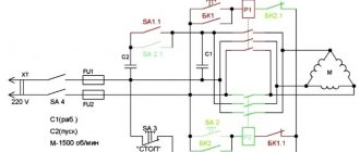
Electrical equipment
The electrical equipment of the milling machine is represented by a power supply network with a voltage of 380 V. The alternating current frequency is 50 Hertz. There are two control networks, one supplying 110V AC and the other supplying 65V DC.
The machine is equipped with light devices up to 24 V. In this case, the sum of simultaneously operating electric motors of the machine cannot exceed 20 Amperes. At the same time, up to 65 Amperes are observed in protective devices, for example, sensors, automatic power and shutdown regulators, fuses of structural components of the mechanism.
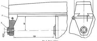
How does the rotating head of the machine work?
The image above shows the current drawing of the rotary head, which is used in the 6T12 machine. It is centered in the annular recess located in the neck of the frame, secured with 4 bolts that fit into 1 different groove of the frame flange.
The spindle consists of a double-bearing shaft, which is integrated into the sliding sleeve. Adjusting the axial play comes down to the need to grind rings 4 and 3. Elimination of increased play in the front bearing becomes possible by tightening the nut and grinding ring 5. The owner is required to follow the correct maintenance procedure. To get rid of the radial play, the value of which is one hundredth of a millimeter, a grinding of approximately 0.12 millimeters is required.
The spindle rotates through a pair of cylindrical and conical wheels that are installed in the head. The gears and bearings installed in the turning head are lubricated by a pump in the frame. Bearings responsible for the correct operation of the sleeve movement mechanism and spindle rotation - using the injection method.
How to Design a 5V 2A SMPS Power Circuit
The power supply unit (PSU) is an important part of any electronic product design. Most consumer electronic devices such as mobile chargers, Bluetooth speakers, power banks, smart watches, etc. require a power supply circuit that can convert AC supply voltage to 5V DC for them to operate. In this project we will build a similar AC to DC with a power rating of 10W. That is, our circuit converts 220V AC power to 5V and provides a maximum output current of up to 2A. This power rating should be sufficient to power most electronic devices that operate at 5V. Also 5V 2A SMPS circuit is quite popular in electronics as there are many microcontrollers that operate on 5V.
The idea behind the project is to make the build as simple as possible, so we will design the complete circuit on a dot board (circuit board) and also create our own transformer so anyone can reproduce this design or create similar ones. Horny right! So let's begin. Previously, we also created a 12V 15W SMPS circuit using PCB so that those who are interested in PCB design for PSU (power supply) project can check it out too.
Scheme
5V 2A SMPS - Specifications
Different types of power supplies behave differently in different environments. Additionally, SMPS operates within certain I/O boundaries. Proper specification analysis must be performed before moving forward with the actual design.
Input data:
This will be an SMPS in the AC-DC domain. Therefore the input will be AC. For the input voltage value, it is recommended to use the universal input rating for SMPS. Therefore, the AC voltage will be 85-265 VAC with a nominal frequency of 50 Hz. Thus, SMPS can be used in any country regardless of the AC mains voltage.
Output characteristic:
The output voltage is selected as 5V with 2A rated current. So it will be 10W power . Since this SMPS will provide a constant voltage regardless of the load current, it will operate in CV (constant voltage) mode. This 5V output voltage should be constant and stable even at the lowest input voltage during the maximum load (2A) on the output.
It is highly desirable for a good power supply to have a ripple voltage of less than 30 mV pk-pk . The target ripple voltage for this SMPS is less than 30mV peak-to-peak ripple. Since this SMPS will be built into the Veroboard using a handmade , we can expect slightly higher ripple values. This problem can be avoided by using a printed circuit board.
Protective functions:
There are various protection circuits that can be used in SMPS for safe and reliable operation. The protection circuit protects the SMPS as well as the associated load. Depending on the type, the protection circuit can be connected via an input or an output.
This SMPS will use surge protection with a maximum input operating voltage of 275 VAC. Additionally, to address EMI problems, a common mode filter will be used to eliminate the generated EMI . On the output side we will include short circuit protection , over voltage protection and over current protection .
Power management IC selection
Each SMPS circuit requires a power management IC, also known as a switching IC or SMPS IC or drier IC. Let's take stock of the design to select the ideal power management IC that will suit our design. Our design requirements
- 10 Watts of power. 5V 2A at full load.
- Universal input rating. 85-265 VAC at 50 Hz
- Input overvoltage protection. Maximum input voltage 275 VAC.
- Protection against output short circuit, overvoltage and overcurrent.
- Operations with constant voltage.
From the above requirements, there is a wide range of ICs to choose from, but for this project we chose Power Integration . Power Integration is a semiconductor company that has a wide range of power driver ICs in different output power ranges. Based on requirements and availability, we decided to use the TNY268PN from the Tiny Switch II family . Previously, we used this IC to build a 12V SMPS circuit on a PCB.
The image above shows a maximum power of 15W. However, we will do SMPS in open frame and for universal input rating. In such a segment, TNY268PN can provide 15W of power. Let's look at the pinout.
Designing a 5V 2A SMPS Circuit
The best way to build a 5V 2A SMPS Schematic is to use PI integration software with experts. Download PI expert software and use version 8.6. This is an excellent software for power supply design. The circuit shown below was built using PI Integration Power software. If you are new to this software, you can refer to the design section of this 12V SMPS Circuit to understand how to use the software.
Before proceeding with the actual prototyping, let's take a look at the circuit diagram of a 5v 2A SMPS and how it works.
The diagram has the following sections-
- Input surge protection and SMPS
- AC-DC conversion
- PI filter
- Driver Circuit or Switching Circuit
- Undervoltage protection.
- Clamp diagram.
- Magnetics and galvanic isolation.
- EMI filter
- Secondary rectifier and snubber circuit
- Filter section
- Feedback section.
Input surge protection and SMPS :
This section consists of two components, F1 and RV1. F1 is a 1V 250V AC fuse and RV1 is a 7mm 275V MOV ( Metal Oxide Varistor ). During a high voltage surge (above 275 VAC), the MOV freezes and blows the input fuse. However, due to the slow-blow feature, the fuse will withstand the inrush current through the SMPS.
AC-DC conversion :
This section is regulated by a diode bridge. These four diodes (inside DB107) make up a complete bridge rectifier. The diodes are 1N4006, but the 1N4007 standard will do the job just fine. In this project, these four diodes are replaced with a DB107 full bridge rectifier.
PI filter :
Different states have different EMI suppression standards. This design complies with the EN61000-Class 3 standard , and the PI filter is designed to reduce common mode . This section is created using C1, C2 and L1. C1 and C2 are 400V 18uF capacitors. This is an odd value, so 22uF 400V is selected for this application. L1 is a common mode choke that accepts the differential EMI signal to cancel both.
Drive circuit or switch circuit :
This is the heart of SMPS. The primary side of the transformer is controlled by the TNY268PN switching circuit. The switching frequency is 120-132 kHz. Due to the high switching frequency, smaller transformers can be used. The switching circuit consists of two components: U1 and C3. U1 is the main driver of IC TNY268PN. C3 is a bypass capacitor that is required for our driver IC to work.
Undervoltage protection :
Undervoltage protection is provided by sensitive resistors R1 and R2. It is used when the SMPS goes into auto restart mode and senses the line voltage. The R1 and R2 values are generated using the PI Expert . Two resistors in series is a safety measure and good practice to avoid resistor failure issues. Thus, instead of 2M, two 1M resistors are used in the series.
Clamp diagram :
D1 and D2 - clamp diagram. D1 is a TVS diode and D2 is an ultra-fast recovery diode . The transformer acts as a huge inductor through the TNY268PN power driver IC. Therefore, during the turn-off cycle, the transformer generates high voltage surges due to the leakage inductance of the transformer. These high frequency voltage surges are suppressed by the diode clamp on the transformer. UF4007 is selected for ultra-fast recovery and P6KE200A is selected for TVS operation. According to the design, the target clamp voltage (VCLAMP) is 200V. Therefore, P6KE200A is selected, and for ultra-fast locking problems, UF4007 is selected as D2.
Magnets and galvanic isolation :
The transformer is a ferromagnetic transformer, and it not only converts high voltage alternating current to low voltage alternating current, but also provides galvanic isolation.
EMI filter :
EMI filtering is carried out by capacitor C4. This improves the circuit's noise immunity to reduce high electromagnetic interference. This is a Y-class capacitor with a rated voltage of 2 kV.
Secondary rectifier and damper circuit :
The output of the transformer is rectified and converted to DC using D6, a Schottky rectifier diode. The damping circuit on D6 provides transient voltage suppression during switching operations. The damping circuit consists of one resistor and one capacitor, R3 and C5.
Filter section:
The filter section consists of filter capacitor C6. This is a low ESR capacitor for better ripple suppression. Additionally, an LC filter using L2 and C7 provides better output ripple suppression.
Feedback section :
The output voltage is measured by U3 TL431 and R6 and R7. After detecting the U2 line, the optocoupler is controlled and galvanically decouples the secondary feedback measurement section from the primary side controller. The optocoupler has a transistor and an LED inside. By driving the LED, the transistor is controlled. Since the communication is optical, it does not have a direct electrical connection, so it also satisfies galvanic isolation in the feedback circuit.
Now, since the LED directly drives the transistor, providing sufficient bias on the optocoupler LED, it is possible to drive the optocoupler transistor , more specifically the drive circuit. This control system uses TL431 shunt regulator. Since the shunt regulator has a resistor divider across its reference pin, it can drive an optocoupler LED that is connected to it. Contact feedback has a reference voltage of 2.5V . Therefore, TL431 can only be active if the voltage across the divider is sufficient. In our case, the voltage divider is set to 5V. Therefore, when the output reaches 5V, the TL431 receives 2.5V through the reference pin and thus activates the optocoupler LED, which drives the optocoupler transistor and indirectly controls the TNY268PN. If the output voltage is not enough, the switching cycle is immediately stopped.
The TNY268PN first activates the first switching cycle and then detects its EN pin. If everything is ok, it will continue switching, if not, it will try again after a while. This cycle continues until everything returns to normal, which will prevent short circuit or overvoltage problems. This is why it is called with a flyback topology , since the output voltage is returned to the driver to determine the associated operations. Additionally, the trial cycle is called a failure mode failure mode.
D3 is a Schottky diode. This diode converts the high frequency AC output to DC. 3A 60V Schottky diode is selected for reliable operation. R4 and R5 are selected and calculated by the PI expert. It creates a voltage divider and transfers current to the optocoupler LED from the TL431.
R6 and R7 are a simple voltage divider calculated using the formula TL431 REF Voltage = (Vout x R7) / R6 + R7 . The reference voltage is 2.5V and Vout is 12V. By selecting the R6 value of 23.7 thousand, R7 became approximately 9.09 thousand.
Building a switching transformer for our SMPS circuit
Usually SMPS circuit requires a switching transformer, these transformers can be purchased from transformer manufacturers according to your design requirements. But the problem here is that if you study prototyping material, you cannot find the exact transformer off the shelves for your design. So, we will learn how to build a switching transformer based on the design requirements given by our PI Expert software.
Let's look at the generated transformer construction diagram.
As shown in the picture above, we need to make 103 turns of one 32 AWG wire on the primary side and 5 turns of two 25 AWG wires on the secondary side.
In the above image, the starting point of the windings and the direction of the winding are described in the form of a mechanical diagram. To make this transformer, the following things are required −
- EE19 core, NC-2H or equivalent specification with clearance for ALG 79 nH/T 2
- Bobbin with 5 contacts on primary and secondary side.
- Barrier tape 1 mil thick. Requires 9mm wide tape.
- 32 AWG Enameled Soldered Copper Wire.
- 25AWG Enameled Soldered Copper Wire.
- LCR meter.
EE19 core with Typically it is available in pairs. The bobbin is shared with 4 primary and 5 secondary pins. However, this one uses a bobbin with 5 pins on both sides.
Barrier tape uses standard adhesive tape with a backing thickness greater than 1 mil (typically 2 mil). During tapping activities, scissors are used to cut the tape to the ideal width. Copper wires are sourced from old transformers and can be purchased from local stores. The core and bobbin I use are shown below
Step 1: Add solder to the 1st and 5th pins on the primary side. Solder the 32 AWG wire on pin 5 and the winding direction is clockwise. Continue until 103 turns as shown below
This forms the primary side of our transformer, when 103 turns of winding are completed my transformer looked like this.
Step 2: Apply adhesive tape for insulation, you need 3 turns of adhesive tape. This also helps keep the reel in place.
Step 3: Run the secondary from pins 9 and 10. The secondary side is made of two strands of 25AWG enameled copper wires. Solder one copper wire to pin 9 and the other to pin 10. The winding direction is clockwise again. Continue up to 5 turns and solder the ends on pins 5 and 6. Add electrical tape, applying the duct tape in the same way as before.
After the primary and secondary windings were done and duct tape was used, my transformer looked like below
Step 4: Now we can securely attach the two cores using duct tape. After this, the finished transformer should look like this.
Step 5: Also, don't forget to place some tape nearby. This will reduce vibration when transmitting high density flow.
After following the above steps and testing the transformer using LCR meter as shown below. The meter shows an inductance of 1.125 mH or 1125 e.h.
Building the SMPS circuit:
Once the transformer is ready, we can start assembling other components on the dotted board. The required parts for the circuit can be found in the specification list below
Once the components are soldered, my board looks something like this.
5V 2A SMPS circuit testing
To test the circuit, I connected the input side to the power supply via VARIAC to control the input AC voltage. The output voltage at 85 VAC and 230 VAC is shown below-
As you can see in both cases, the output voltage is maintained at 5V. But then I connected the output to my scope and checked for ripple. Ripple measurement shown below
The output ripple is quite high, it shows a ripple output of 150mV pk-pk. This is not at all good for the power supply chain. Based on the analysis, high pulsation is due to factors below-
- Incorrect PCB design.
- Bouncing off the ground.
- The PCB heatsink is not suitable.
- No shutdown on noisy supply lines.
- Increased tolerances on the transformer due to hand winding. Transformer manufacturers use dip varnish during machine windings for better stability of transformers.
If the circuit is converted to a proper PCB, we can expect a pulsating power supply output within 50mV pk-pk even with a hand-wound transformer. However, since veroboard is not a safe option for switching switching power supply in the AC to DC domain, it is always suggested to install a proper PCB before applying high voltage circuits in practical scenarios. You can check the video at the end of this page to check how it works diagram under load conditions.
I hope you understood the tutorial and learned how to create your own SMPS circuits using a handmade transformer. If you have any questions, please leave them in the comments section below or use our forums for additional questions.
,
Specifications
Component Location
To become familiar with the operational and performance characteristics of the 6P12 machine, it is necessary to study the equipment passport in detail. Since this model belongs to the professional category, before performing milling, the worker must undergo safety training and become thoroughly familiar with the operating principle of the elements and assemblies.
The weight of the machine with all installed equipment is 3120 kg. Its dimensions do not exceed 228*196.5*226.5 cm. When compared with similar models, you will notice that the dimensions of the machine are larger than standard. This must be taken into account when choosing an installation location.
The main technical characteristics of the 6P12 model are indicated in detail in the passport. But to select the correct operating mode, you should know the following machine parameters:
- desktop dimensions – 125*32 cm;
- the maximum permissible weight of the workpiece being processed is 250 kg;
- desktop progress. In the longitudinal direction – up to 80 cm; in transverse – 25 cm;
- maximum vertical displacement of the table surface – up to 42 cm;
- the nominal speed of the spindle head varies from 40 to 2000 rpm;
- number of spindle speeds – 18;
- the spindle quill can change its position by 70 mm;
- the number of table feeds is the same for all directions (longitudinal, transverse and vertical) and is 22.
The power of the electric motor of the main spindle drive is 7.5 kW. To activate the high-speed clutch of the working table, the 6р12 vertical milling machine has in its design special gears connected to the power plant shaft.
Recommendations for use
Electrical diagram of the machine
Before starting work on the machine, it is necessary to study the equipment passport and its characteristics. It presents technical requirements for installation, operating rules and procedures for carrying out repair and maintenance work.
The choice of equipment installation location is determined according to its dimensions, weight and characteristics. In this case, it is necessary to take into account the free space for the worker, as well as the installation of the workpiece on the work table. In the latter case, special lifting mechanisms are often used.
Additionally, the passport contains the following recommendations for the operation of the 6P12 vertical milling machine:
- After unpacking, it is necessary to remove the protective and lubricating layer from the surface of the machine. For this purpose, special compounds are used;
- performing the procedure for lubrication of units and components according to the diagram in the passport;
- Before starting work, the absence of defects and the correct configuration of the equipment are checked. It is taken into account that its actual performance indicators may differ from the nominal ones due to long-term operation;
- After installing the cutter, it is necessary to install a protective fence. It is included as standard equipment;
- Upon completion of installation, the machine starts at idle speed without installing the workpiece. All operating modes are checked.
A short video review will give you an impression of the capabilities of the 6P12 machine:
Vertical milling machine mod. 6T12, 6T13 (analogous to 6P12, 6P13, VM127M).
DESIGN FEATURES OF MACHINE 6T-12, 6T-13.
- Availability of various automatic milling cycles.
- Automated lubrication of components.
- Automated tool mounting in the spindle.
- Availability of a mechanism for proportional feed slowdown.
- Electromagnetic clutches for controlling coordinate switching.
- The presence of a gap limiting device in the longitudinal stroke screw pair.
- Mechanical safety clutch for feed drive protection.
- Electromagnetic clutch brakes the spindle when stopping.
TECHNICAL CHARACTERISTICS OF THE CONSOLE MILLING MACHINE:
| Vertical milling console machine mod. 6T12, 6T13 are widely used in various modern metalworking industries to perform a variety of milling operations using cylindrical, angular, shaped, face and other cutters; when processing horizontal, vertical planes, grooves, frames, corners, gears, stamp models, molds and other parts made of steel, cast iron, non-ferrous metals and their alloys. | ||
| 6T12 | 6T13 | |
| Spindle end, GOST 24644-81 | 50, 40 | 50, 40 |
| Maximum permissible diameter of cutters, mm spindle of rotary head | 160 | 200 |
| Dimensions of the working surface of the table, mm width length | 3201250 | 4001600 |
| Maximum table movement, mm longitudinal transverse vertical | 800320420 | 1010400430 |
| Number of T-slots | 3 | 3 |
| Number of rotational speeds of the spindle of the rotary head | 18 | 18 |
| Spindle speed limits, rpm. rotary head | 31,5…1600 | 31,5…1600 |
| Number of table feeds | 22 | 22 |
| Table feed limits, mm/min. longitudinal and transverse vertical | 12,5…16004,1…530 | 12,5…16004,1…530 |
| Speed of rapid table movement, mm/min. longitudinal transverse | 40001330 | 40001330 |
| Proportional slow feed, mm/min. | 1/2S | 1/2S |
| Electric motor power, kW main feed movement | 7,53 | 113 |
| Machine dimensions, mm length width height | 228019652265 | 257022522430 |
| Machine weight, kg | 3200 | 4250 |
Contents of delivery:
| Designation | Name | 6Т12-29 | 6Т13-29 |
| Complete machine | 1 | 1 | |
| Included in the kit and the cost of the machine | |||
| Dismantled parts | |||
| Protective device | 1 | 1 | |
| Cutting area guard | 1 | 1 | |
| Valve with nozzle | 1 | 1 | |
| Manual movement handle | 1 | 1 | |
| Handwheel | 1 | 1 | |
| Table shield | 2 | 2 | |
| Lamp NKSO1x100/P20-01U4 | 1 | 1 | |
| Lamp MO24-40U3 | 1 | 1 | |
| Rear casing | 1 | 1 | |
| Accessories and tools | |||
| 6T82G.880.254 | Key to electrical cabinet | 1 | 1 |
| 6222-0134 | Mandrel | 1 | 1 |
| 6Р12К.93.100/42А | Capture | 1 | 1 |
| 24.65G.05 | Washer GOST 6402-70 | 1 | 1 |
| 6Р12К.93.100/41А | Capture | 1 | 1 |
| 191.831.055 | Transitional sleeve | 1 | 1 |
| Documentation | |||
| 6T12-29.000.000 RE | Manual. Part I | 1 | 1 |
| 6T82G-29.000.000 RE1 | Manual. Part II. | 1 | 1 |
| 6T82G-29.000.000RE2 | Information about acceptance, preservation, packaging. Part III. | 1 | 1 |
Accessories available at extra cost:
| The digital display device, DRO, increases operator productivity and the accuracy of manufactured parts. DRO systems do not have the backlash inherent in mechanical measurement systems and allow the old machine to work with the accuracy of a new one. The DRO system allows you to display the actual position of the machine axes, taking into account complete and incomplete sampling of backlash. | |
| Adjustable wedge supports. | |
| Vibration supports. | |
| Rotary machine vice with manual drive 250 mm steel. | |
| Rotary machine vice with manual drive 250 mm cast iron. | |
| Cast iron rotary pneumatic vice with hydraulic reinforcement. | |
| Collet chuck included (collets Ø3, 4, 5, 6, 8, 10, 12, 14, 15, 16). | |
| Mandrel for attachment end mills Ø22, 27, 32, 40, 50. | |
| Adapter sleeve cone to Morse cone No. 1, 2, 3, 4, 5. | |
| Universal long-lasting head UDG-250 or UDG-160 (320mm). | |
| Round rotary table Ø250 mm or Ø400 mm horizontal. | |
| Round rotary table Ø250 mm or Ø400 mm horizontal-vertical. | |
| Round rotary table Ø250 mm tiltable. |
You can order and buy a vertical milling machine 6T12, 6T13 by ordering shipment by transport companies to the cities: Arkhangelsk, Vladivostok, Volgograd, Voronezh, Ekaterinburg, Izhevsk, Irkutsk, Kazan, Kemerovo, Krasnodar, Krasnoyarsk, Moscow, Nizhny Novgorod, Novosibirsk, Omsk , Orenburg, Penza, Perm, Rostov-on-Don, St. Petersburg, Samara, Saratov, Tyumen, Ufa, Cheboksary, Chelyabinsk, Yaroslavl and other regions of Russia.
Technical description of vertical milling machine 6Р12
The technical description of the 6P12 vertical milling machine contains information necessary both for the operating personnel of this machine and for the employee directly involved in working on this machine. This manual is an electronic version in PDF format of the original paper version with some chapters missing.
You can download the “Technical description of the 6P12 vertical milling machine” for free in good quality from the link below:
Rules and operating instructions, passport
The operating instructions contain separate diagrams for bearings, slinging, lubrication, kinematics, as well as a description of electrical equipment. For parts that are subject to rapid wear, a separate drawing of each element is also provided.
Unification allows you to use parts from similar machines of the same series. When working on 6T12 equipment, you must strictly follow all safety rules, since otherwise the unit can injure a person:
- checking grounding before starting work;
- checking that the voltage in the network matches that required by the machine;
- be sure to check the serviceability of the brake, signal and push-button devices;
- make sure that the cooling and lubrication system is well established;
- You should work in overalls, with your hair tucked under your headdress and your sleeves tightly buttoned;
- It is prohibited to approach the machine under the influence of alcohol or drugs, as well as various medications.
To be allowed to work on such equipment, a specialist undergoes training, as well as special safety instructions. If there is any problem with the operation of the main components, it is necessary to turn off the engine and conduct an initial diagnosis of the equipment in order to identify the cause and eliminate the breakdown.
Main technical indicators and advantages
Despite the fact that the presented model has been produced in Russia for more than 30 years, this does not prevent the machine from still creating good competition with more modern models. There are several reasons for this.
For example, the minimum deviation in the location of the treated surface and its shape is explained by the fact that the load-bearing elements have higher rigidity. Also, to increase rigidity, scraped guides with a compatible profile are used.
The spindle supports used by the vertical milling machine are equipped with paired angular contact and double-row roller bearings, which are characterized by increased load capacity. This facilitates power cutting with high quality processing. If standard lubrication is used, and the structural elements themselves have the correct tension, the bearing life will be longer than the amount of time before a major overhaul. To determine the class of bearings, you must read the technical data sheet.
In a screw pair, backlash is eliminated using a specially designed movable nut, which is included in the axial play control mechanism. Bimetallic materials are used in the production of all running nuts. Parts subject to more accelerated wear in areas of friction are produced using steel that is surface hardened with high-frequency heat. Exactly the same heat treatment method is used to strengthen gears. As a result, the equipment operates for a long period of time without the need for maintenance. And when the time comes to complete it, the cost of spare parts will be minimal.
The composition of a centralized effective lubrication system includes two groups. The first includes lubricant for the mechanisms in the console, and the second includes an oil supply system for the mechanisms located in the frame. Each of them, accordingly, provides separate power from its own plunger-type pump.
Increased drive power reserves, a wide range of speeds and feeds, minimal system compliance - all this contributes to high-performance processing of metal workpieces, which include plates made of STM or high-strength materials.
Achieving additional time savings is made possible thanks to the electromechanical method of fixing the tool. The table itself moves in automatic cycles. The revolutions are switched without sequential passage of steps.
Components
Considering the main characteristics, the basic design advantages of this equipment model are the presence of the following components:
- a device for slowing down the feed speed (the machine uses a proportional circuit);
- a mechanism to protect against metal shavings falling on the operator and others;
- an electromagnetic clutch that effectively brakes the spindle assembly in the horizontal plane;
- clutch to protect the main feed electric motor from overload;
- a device that allows you to adjust the gap in the screw pair (when feeding in the longitudinal direction).
It is also worth noting that the fixation of working tools on this machine is carried out according to a mechanized principle. Thus, the manufacturer was able to achieve a significant reduction in the time required to process a metal workpiece.
galvanized 2p electrical switch
Quality Galvanized 2 Pin Circuit Breaker
Quality 2 Pin Circuit Breaker
Product Description
Quality Galvanized 2 Pin Circuit Breaker
GENERAL USE Direct-fit poles minimize site requirements, reducing rental rates and purchasing costs. They are designed for quick installation and meet the demands of today's dynamic communications environments. Whether you are using broadband-enabled, PCS, security or other lightweight systems, ROHN tapered steel poles offer an exceptionally wide range of designs. FEATURES for 2 Pin Electrical Switch • Fully hot-dip galvanized after manufacture • Quick and easy installation • Designed for applications with stringent electrical requirements
• Internal power line routing • Each pole comes with the following: • Assembly drawings and standard foundation details • (4) 5” x 7” ports with (2) port covers • (3) Clamping lugs on each side of connectors • (3) Grounding Clamps • (1) Vented Safety Cap • (1) Base Plate Welded to Bottom • Safety Support Brackets for 2-Pole Electrical Switch • (1) Safety Warning Label • (1) Pole Identification Mark • Mounting Clips for Optional Step Bolts • Additional items are available and can be ordered separately. See Accessories on page 225. • Custom designs available to suit any height or application.
| Height | From 9 meters to 100 meters |
| Suit for | Electricity transmission and distribution |
| Form | Polygonal or conical |
| Material | Typically Q345B/A572, minimum yield strength ≥ 345 N/mm² Q235B/A36, minimum yield strength ≥ 235 N/mm² , as well as hot rolled coil from ASTM A572 GR65, , SS400 |
| Power | from 10 kV to 220 kV |
| Measurement tolerance | According to customer's requirements. |
| Surface treatment | Hot dip galvanized in accordance with ASTM A 123 or any other standard required by the client. |
| Pole connection | Sliding connection, flange connection |
| Standard | ISO 9001:2008 |
| Length per section | Within 14 meters after molding |
| Welding standard | AWS (American Welding Society) D 1.1 |
| Thickness | 1 mm to 36 mm |
| Manufacturing process | Raw material testing → Cutting → Bending → Welding (longitudinal) → Dimensional checking → Flange welding → Hole drilling → assembly sample → clean surface → galvanizing or powder coating, painting → recalibration → bags |
| packages | Packing in plastic paper or as per customer's request. |
| Product name | Two position electrical switch |
| Length per section | Within 14m after molding without slipping |
| Minimum tensile strength | 490mpa |
| Maximum tensile strength | 620mpa |
Information about the company
Information about the company
for 2-pin electrical switch
Yixing Futao Metal Structural Unit Co.Ltd is located in No.8 Nanxin East Road, Heqiao City, Yixing City, Jiangsu Province. Equipped with a series of CNC conveyor systems for leveling, cutting, folding and automatic welding, we could produce high and medium mast lighting, road lighting power poles, observation lights, lighting lamps, lawn lights, traffic light poles, monitor poles, microwave communication poles etc. In addition, our production process is ISO9001 certified. length 13,000mm and thickness 2-20mm.
Our website: https://www.chinasteelpole.com/ https://www.fu-tao.com/
2-pin electrical switch
Trade Assurance:
Trade Assruance: Our Trade Assurance Limit: US$532,000
for quality galvanized double pole electric switch
produced by Prcess
Production process: for quality galvanized double pole electric switch material cutting test → Casting or bending → Welidng (longitudinal) → Dimensions checking
→ Flange welding → Hole with holes → Sizing → Cutting → Galvanizing or powder coating, painting → Re-sizing → Threading → Bags
Transaction history
Transaction History for Quality Galvanized 2 Pin Electrical Switch e Below is information about our transactions conducted through Alibaba.com. If you require further information about your transaction details, please contact us directly.
Our services
Our services
quality 2p galvanized electrical switch
1. Reply your inquiry within 24 business hours.
2. Experienced staff will answer all your questions in fluent English.
3. Custom design is possible. UEM and UBM are welcome.
4. Exclusive and unique solution can be provided to our clients by our well trained and professional engineers and staff.
5. Special discounts and sales protection are provided to our distributor.
6. Professional Factory: We are a manufacturer specialized in producing all kinds of steel poles for over 20 years,
competitive with good quantity.
Certificates
Quality Certificates Galvanized 2 Pin Electrical Switch
We have certificates for SGS and ISO9001.
FAQ
FAQ about Quality Galvanized 2 Pin Electrical Switch
1.Price term: FOB, CFR or CIF.
The price includes the pole shaft, base, cross member and anchor part. Shanghai seaport.
For FOB, CFR or CIF price, please indicate which model you need and then tell us your order quantity to
so that we can calculate local shipping and sea freight.
2. MOQ: 1 set for customized
3. Payment: Usually 30% by T/T as deposit, balance by T/T or L/C in sight before shipment.Other payment
the method is negotiable.
4. Delivery time:
Items can be ready to ship within 10 business days after receiving deposit.
5 Warranty: 30 years
6. Surface treatment: hot-dip galvanizing
,
Purpose of the machine
The series of machines has various modifications, but many characteristics within the model range remain the same. 6M12P is an improved version of the N series.
Thanks to the use of such devices, you can perform a large number of operations:
- Milling of various parts based on materials such as non-ferrous and ferrous metals, cast iron and steel. The shape can be any - radius and end, cylindrical, end.
- Support for automatic and semi-automatic cycles. Thanks to this, the machines become indispensable assistants when performing work with an operational nature, with fully automated lines.
- The machines allow you to process horizontal and vertical surfaces, grooves and corners.
- Milling can be counter or down milling.
- High-speed milling is a processing method that makes equipment especially efficient.